Bolton Tools ZX1048P Technical manual

MODEL ZX1048P and ZX1048PD
Milling and Drilling Machine with Rotary Head
OPERATION INSTRUCTION
Number of machine___________________

1. Attention
1.1 Inspection and acceptance
Please check carefully when open the package and make sure no parts are
missing.
1.2 Safety
Please read the operation manual carefully before the installation and
adjustment of the machine,when finish the installation,check all tile
details and trial run the machine idyll before put it into operation.
1.3 Caution
Keep in mind the safety measures for electrical and operating
protection.
2. Work environment
2.1 The elevation of workshop has to be 2000m or less.
2.2 No conductive dust allowed.
2.3 No explosive factor allowed.
2.4 No corrosive gas or steam which may corrode metal or damage the
insulation.
2.5 Keep away from the source of impact or vibration.
3.Operation Instruction
3.1 Before starting the machine,read carefully the operation manual and
be fully acquainted
with the details.
3.2 The operate should be familiar with all the rules and points of attention
of running and maintaining the machine.

3.3 Remove all the anti-rust coating or grease from the machine. Fill the
machine with lubricant. Run the machine from low to high speed and check
if is normal.
3.4 There’s a reliable ground protection the ground wire must be connected
properly before it in operation.
4. Lubrication
Lubricate the sliding and rotating part before trial run.
Pour NO.40 machine oil into the Gear Box and the Power Feed(optional). Till
indicating through the oil level indicators then do a overall check..
Keep oil level above the mark.
ⅠUSAGE
The machine is used for cutting metals. It’s suitable to drill, mill and
widely use in the field of
instrument, machining for cutting a single part or a batch of parts.
Model ZX5325 serials drilling and milling machine has the characteristic
of strong rigidity and good stability.
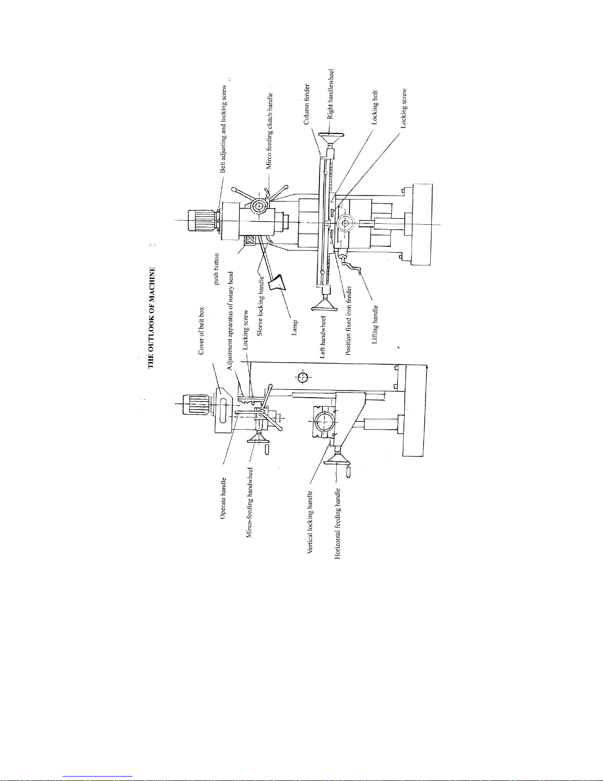
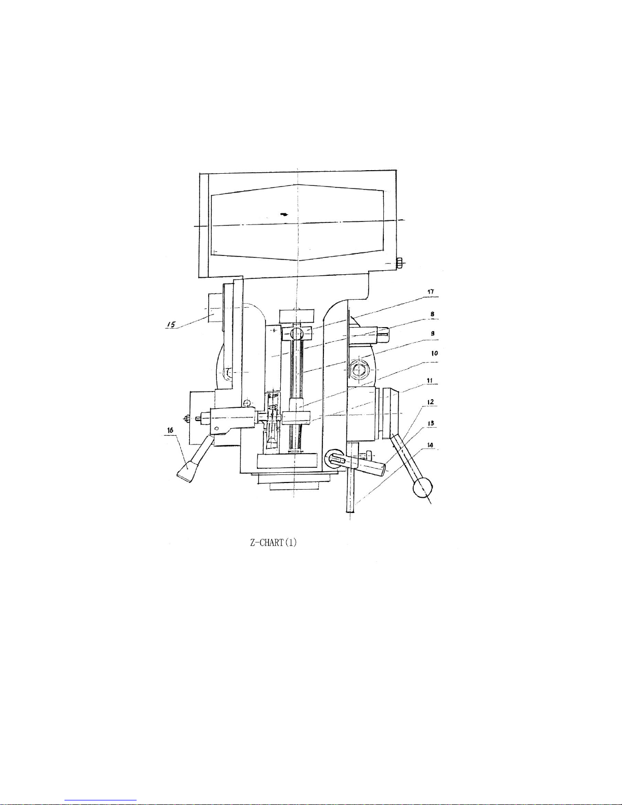
ⅡUSE AND AINTENACE
(Refer to chart 1.)
1. The user must read the operation Manual carefully,know structure and
ability of every
handle,the system of transmission and lubrication well.
2. Before operating,inspect the normal conditions of the column lock
handle,the spindle sleeve and electric equipments. The ground line must
be connect in the ground.
3. When the position of spindle Box to the working table need to be
adjusted,two clamping shaft(1)locating on the right side of Hoist
descend sliding must be lossed firstly, then turn the hoist-descend

handle in front of machine or descend the working table to the idea
position, finally clamp the clamping shaft(1).
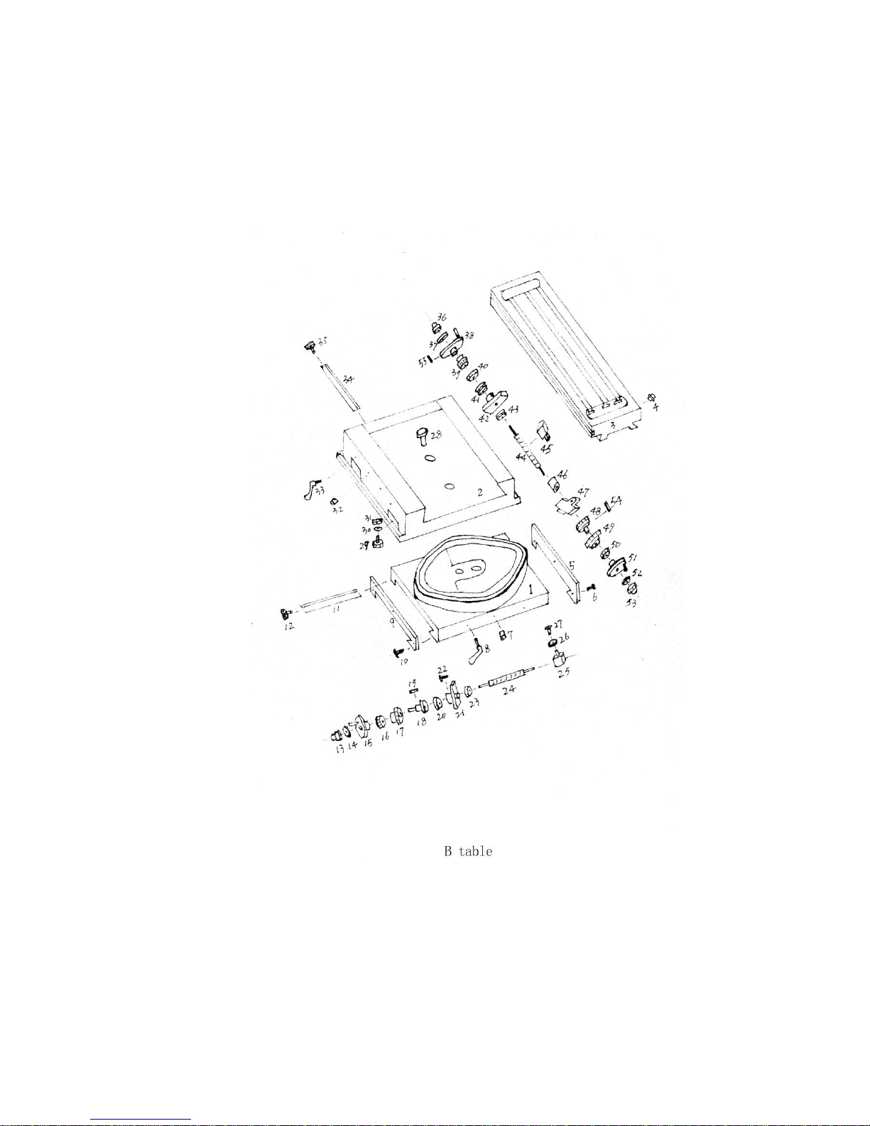
4. The Auto-Feeding and Manual-Feeding for it’s spindle sleeve can be
realized. For Auto-Feeding,pls engage the safety clutch by
handle(16),then engage the Tri-union sliding gear with three gears
by Handle(15). Three different Feeding(0.08,0.15,0.25mm/r)can be
gained by the spindle sleeve.Spindle sleeve is also with step block
(17)and scale(8), etc, for automatic stopping and size
controlling properly.
The adjusting shaft(9) on Mill Head,Nut(10)stop-block(17)are for
pro-setting the size. For this, posited the upper scale of the nut(10)the
scale and tight the nut(11).
When auto-feeding, stop-Block(17) touch nut(10),they will press the clutch
off,Feeding will be stopped.Safety is with over-load protection,to avoid
damaging the parts.
Manual-Feeding can be realized by Handle(12) when Handle(16) is off.
Notation:
(1) Please tight the spindle sleeve by Handle(13) when spindle sleeve is
free, pay attention that the force can’t be too much..
(2) Auto-Feed is not allowed when the spindle speed is 1500 rpm, or spindle
reverse.
(3) Bar(14)is for Fixing Gauge.
5. The cross-slide of spindle box can be realized through the ram moving,
for cross sliding,Please firstly loosen, the two clamping
bolts(5)locating on the right side of the ram,turn the gear shaft(6),
to move the ram and spindle box and tight the two clamping bolts.
6. The spindle box can turn 180°around the column in the horizontal plane, to
realize this,Please firstly loosen the 4 pieces of clamping nuts(7)under
the ram,turn the to the suitable position,finally tight the 4 pieces
of clamping nuts.

7. The spindle’s turn and revolve can be realized by turn the switch locked
in right side of hoist-descend sliding.
8. The spindle box that transmitted by the belt can be rotated ±45°in
vertical plane,when operating, Please loose the three
retaining nut and pay attention these nuts need only pitch,then swivel
screw lever by socket head screw(S16-18) to make the spindle box swivel
to the place required.
9. If the machine don’t work well or have irregular noise, Please immediately
shut off machine.
ⅢTechnical data
type
unit
ZX1048PD
ZX5325Z
ZX1048P
Max.drilling
diameter
inch
2″
2″
2″
Max.milling
diameter
inch
1″
1″
1″
Max.diameter-of
griding wheel
inch
4″
4″
4″
Spindle taper
inch
MT4/ISO30
/ISO40/R8
MT4/ISO30/
ISO40/R8
MT4/ISO30
/ISO40/R8
Spindle travel
inch
5″
5″
5″
Table size
inch
50″*10″
50″*10″
50″*10″
Vertical travel of
table
inch
10″- 15″
10″- 15″
10″- 15″
Travel of table
inch
27″*15″
27″*15″
27″*15″
Rotary angle of
table
inch
±45°
±45°
±45°
Rotary angle of
head
inch
±90°
±90°
±90°
Range of speed
inch
8grade 276-2190
4grade 90-2000
9grade 270-2950
Motor
kw
0.85/1.5KW
2.2KW
1.5KW
Note: if you need the vertical travel of table achieve 380mm , a

200mm depth hole needed under the vertical lead-screw on the ground.
Ⅳ.Operation instruction
1.preparation before start
You’d better consult operation instruction before starting. Familiarize
yourself with the structure of the machine and master the uses of each part
and operating manual.
Before starting the machine,clean away rust inhibitor and dirty on the
smooth,then smear it with lubricating oil,especially on guide,guide screw
and other contact surfaces which have relative shift.
First of all, check the mains voltage see if it accord with provide
data,check electrical equipment,earthed wire must be in a good
condition;and the clamping structure is clamping structure is clamped well.
2. adjustment of main-axle speed
The speed of main-axle is adjusted by the motor and two cone pulley.
The speed has six
grades,speed adjustment handle and combined switch control the speed of
this machine. Choose your needed speed according to the instruction on the
speed plate. see details on data plate of speed.
3. Adjustment of angle of inclination of main axle box
If you need inclination of main-axle box,loose the four locking
screws,which on left and
right side of the main axle box. Keep the same resistance,(note:Not loose
too much of the four screw)use spanner,rotate the adjustment apparatus of
rotary of machine head,make the machine head inclination to such degree
angle,then lock the screws.

4. Adjustment if rotary of working table
If you need rotary in aclination of working table in horizontal plane
loose horizontal
feeding handle,rotary the working table to such degree angle and then tight
the rotary plate locking screw.
5.Lifting and locking working table
Loose lift locking bolt and lift locking screw-nail, the lift
handle,put the working table in needed position and then lock them.
6. Moving in length and breadth and locking of working table
(1)vertical feeding by hand and locking:
Loose the two vertical locking screw-nail,lock the hand wheel(left hand
wheel or right hand wheel)on each side if the working table, then you can
get vertical shift,if you do not need shift,lock the screw nail.
(2)vertical power feeding:
We can equip a power feeding apparatus on the right side if the working
table according to customer’s requirement(Note:you must loose the vertical
locking first).see details on operating manual of power feeding apparatus.
(3)Horizontal,shift and locking:
Loose the two horizontal feeding screw-nails on the left side of sliding
block,rock horizontal feeding handle,but if you do not need horizontal
shift,lock the screw-nails.
Eventually,loose the parts which need moving and lock the parts which don’t
need moving.
7.Operating of main-axle
(1)Fast feeding of main-axle
Loose sleeve locking handle and pull out the micro-feeding clutch handle,
rotate the operating handle, the we can get fast feeding.

(2)Micro feeding of main axle:
Puch on the micro-feeding clutch handle,keep it engaged then rotate
micro-feeding hand wheel.
(3)Position fixed of main axle:
If you want to fix position of main axle,loose the position fixed bolt,set
the bolt on the needed position and tight it.If you don’t need fix
position,you must position,you must loose the fix position bolt.
8.Milling
You can use upright or key slot milling cutter from φ4 to φ6, when the
diameter is more than φ20,you can directly use M’Scone handle milling curter
or key slot cutter. If the milling surface is large enough, you can install
section milling cutter.
9.Drilling.
This kind of machine is supplied with drill chuck,reduction sleeve and
connecting bar,So as to drilling,reaming different holes.
10.Boring.
This king of machine can bore different diameter holes.
11.Grinding.
With grinding wheel,the machine can grind surface of all kinds of steel
piece,cost iron and swallow-tailed guide.
Ⅴ.Lubrication of machine.

Rolling bearing and turbine are lubricant by grease,clean and change
grease anally,surface with relative shift use lubricating oil,two times
each shift.
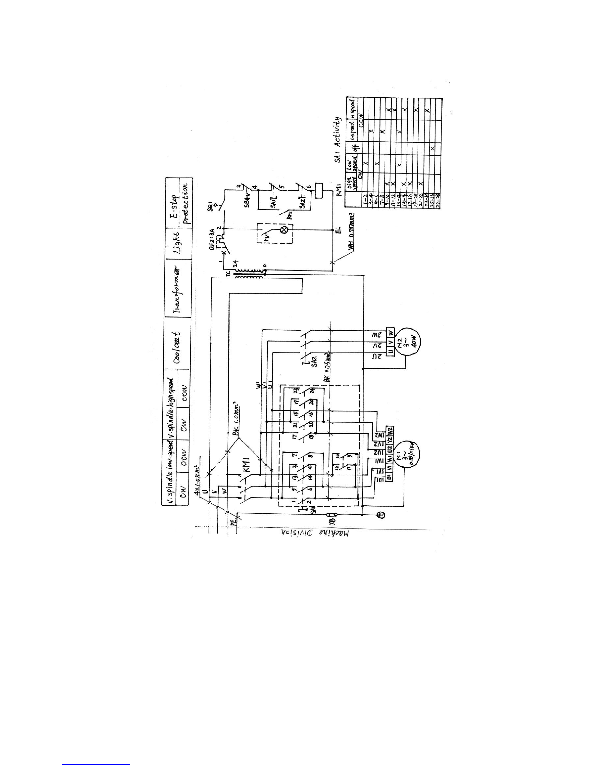
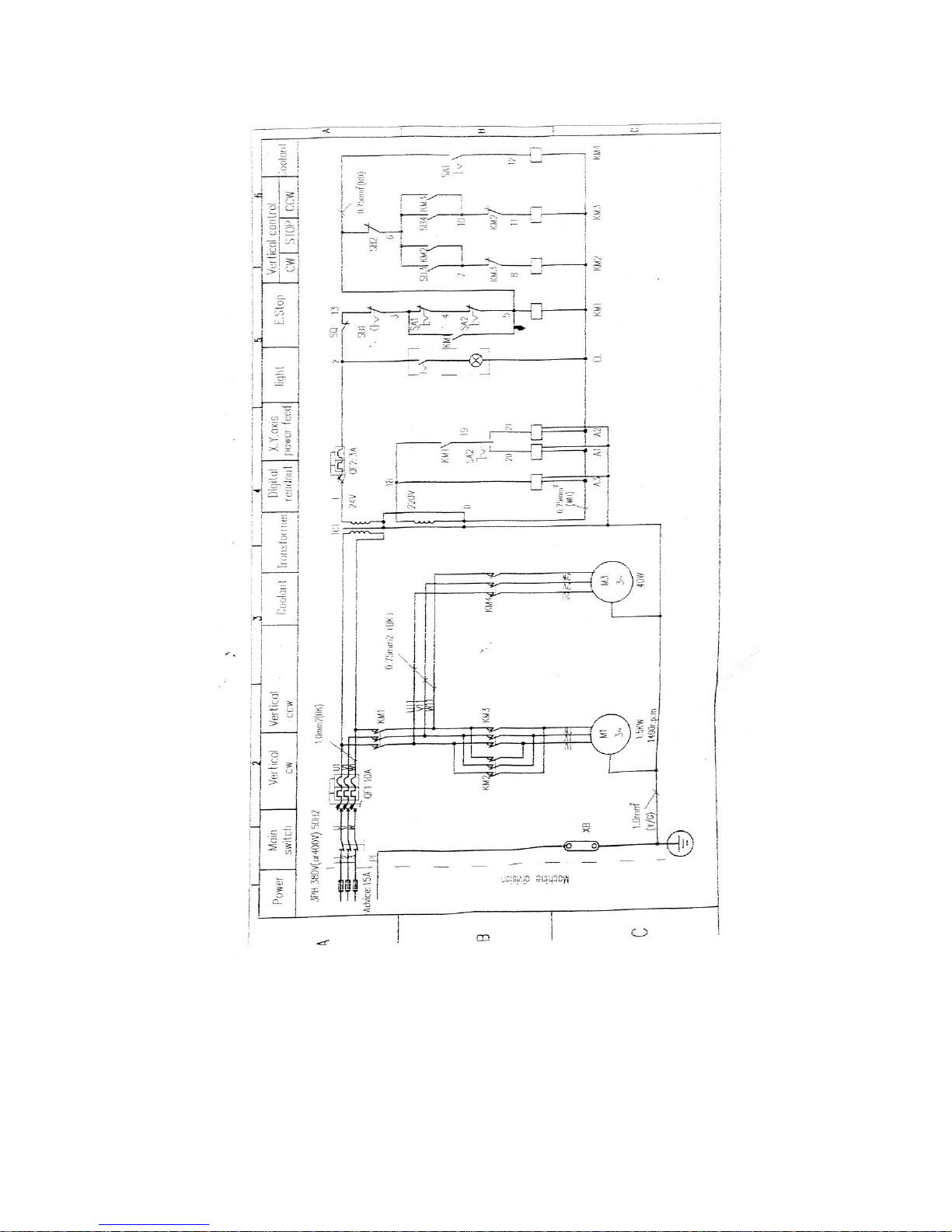
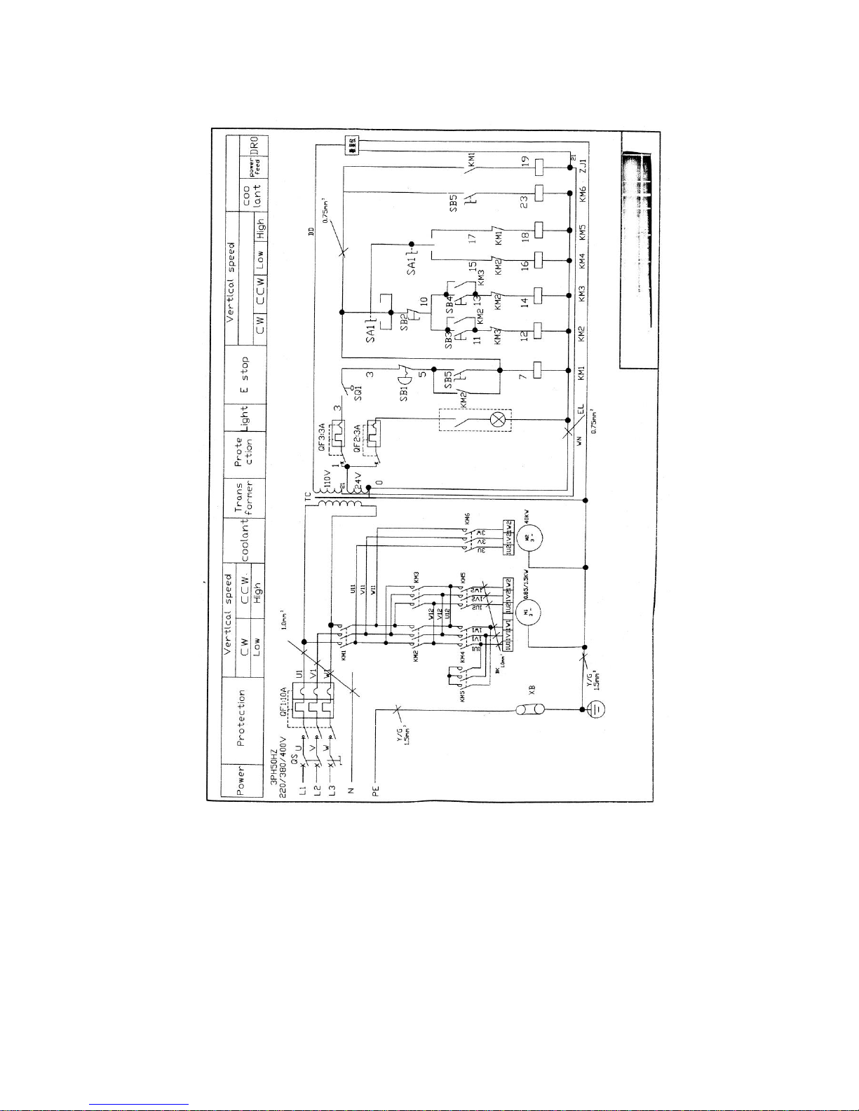
Ⅵ.Electrical equipment of machine:
Electrical schematic diagram and the list of electrical are in
following page.
1.Earthed wire must be in a good condition.
2.This machine use single phase motor,turning and reverse speed is
controlled by combined switch.see details in electrical schematic diagram.
3.If you use power feeding apparatus,you must supply with A.C voltage
110V/50Hz,transformed by 150VA control transformer pay more attention to
this point.
ZX1048P PACKING LIST

Number of machine:
No
name
specification
Q’ty
remarks
1
Drill chuck
Φ1~Φ13
1
2
Connecting bar with
clamping apparatus
ISO40 or MT4
ISO30 or R8
1
3
Boring bar
ISO40 or MT4
ISO30 or R8
1
4
Pull rod
1
5
Six edges spanner
S6 S8
1
6
Double –head spanner
19~17 24
1
7
Reduction sleeve
1
8
Machine vice
160
1
9
Milling chuck
ISO40 or MT4
ISO30 or R8
1
10
Power feed
Special
apparatus
11
Operation instruction
1
12
Packing list
1


A.Boday
NO.
NAME
Q’TY
NO.
NAME
Q’TY
A1
Base
1
36
Dust cover (long)
1
2
Column
1
37
Dust cover (right)
1
3
Knee
1
38
Wedge
1
4
Support(test)
1
39
Lock screw
1
5
Rotary base
1
40
Press bar
2
6
Nut
3
41
Handle ball
1
7
Lead screw
2
42
Bolt
1
8
Bearing
2
43
Handle bar
1
9
Bolt
1
44
Handle collar
1
10
Support collar
3
45
Handle
1
11
Washer
1
46
Key
1
12
Taper gear
2
47
Tow-tooth gear
1
13
Key
1
48
Nut
1
14
Anti-back Washer
1
49
Scale ring
1
15
Nut
1
50
Collar
1
16
Cover
1
51
Hole-chip
1
17
Screw
1
52
Bearing
1
18
Water tube base
1
53
Screw
1
19
Screw
1
54
Collar
1
20
Bolt
1
55
Pin
1
21
Bolt
1
56
Taper gear
22
Pin-screw
4
57
Key
23
Coolant pump base
1
58
Shaft
24
Screw
1
59
Bearing
25
Cover
1
60
Shaft
26
Screw
1
27
Cover
1
28
Screw
1
29
Screw
4
30
Pin
4
31
T-bolt
4
32
Worm-gear
2
33
Screw
2
34
Up-down dust seat
1
35
Dust cover (left)
2
This manual suits for next models
1
Table of contents
Other Bolton Tools Power Tools manuals


