Bonito NTi MegActiv MA305FT User manual
Issue 10/2019
Manufacture: Rudolf Ille Nachrichtentechnik • www.nti-online.de
Distributor:
Bonito - Dennis Walter • Gerichtsweg 3 • D-29320 Hermannsburg • www.bonito.net
TECHNISCHE DATEN
Antenna:
Power supply: 5 - 15V DC (max. 40mA; typ. 10mA)
Connector: BNC / 50 Ohms
Radiator Connector: M6-screws (stainless steel)
Frequency response (-3dB) and nominal gain:
FM-Trap o
9kHz - 300MHz & nom. 3dB Gain
FM-Trap on
9kHz - 52MHz & nom. 3dB Gain
88 - 108MHz typ. -20dB attenuation
IP3: > typ. +30dBm (@7.00 & 7.20MHz)
IP2: > typ. +50dBm (@7.00 & 7.20MHz)
Size / weight: 98 x 90 x 38mm / 0.12kg
Power inserter CPI1500UNI:
Power supply: max 15VDC/max. 400mA current-limited and protected against polarity reversal
Connectors: 2.1mm DC-power socket (positive inner);
Alternatively via optional USB > DC power plug PartNo: 00163-1 HF: BNC
Size/ eight: 86 x 70 x 29 mm / 0.09 kg
Scope of delivery:
MegActiv 305FT
Power inserter CPI1500UNI
200mm exible radiator
Safety instructions
Thunderstorms and overloads
The inputs of the MegActiv MA305FT are triple-protected against static charge. For coarse protection a fast 60
Gas Arrestor (max. 1kA 8/20μs) is used, followed by an 8KV ESD protector according to IEC 61000-4-2 Level 2
/ max. 30ns and another 4KV ne protection.
Disclaimer - please note
The integrated over-voltage protection circuit will not protect your equipment from a lightning strike in the event
of a direct hit to the house or the local vicinity. Irrespective of the loop size, high voltages can be induced which can
permanently damage the antenna electronics and/or connected devices. For this reason, liability for these devices
is excluded. Other types of damage caused by overloads or by direct HF-exposure (transmitting antennas) are
also excluded from the warranty. In case of absence from home, the potential danger and subsequent damage
of transmitting (ham radio stations), and thunderstorms etc., can be avoided by disconnecting the antenna cable.
In the vicinity of strong FM transmitters, please note the following:
An integrated FM band-stop lter with extra low-pass is present at the input of the MA305FT. Thus strong
interference can be eectively suppressed by up to 20dB. In the immediate vicinity of very strong transmitters (circa
a distance of a couple of hundred meters) the antenna electronics and/or connected receivers can occasionally be
overloaded. This is possible whenever the output level is stronger than -20dBm. Weaker signals may be suppressed
or phantom signals may be produced. As the antenna receives up to 300 MHz, signals outside the shortwave range
can also potentially eect the antenna electronics in a similar way.
© 2019 • Subject to technical modications; no responsibility is accepted for the accuracy of this information.
All descriptions are for informational purposes only and cannot be understood as express promises concerning
the properties of the products or as warranties. All trademarks acknowledged.
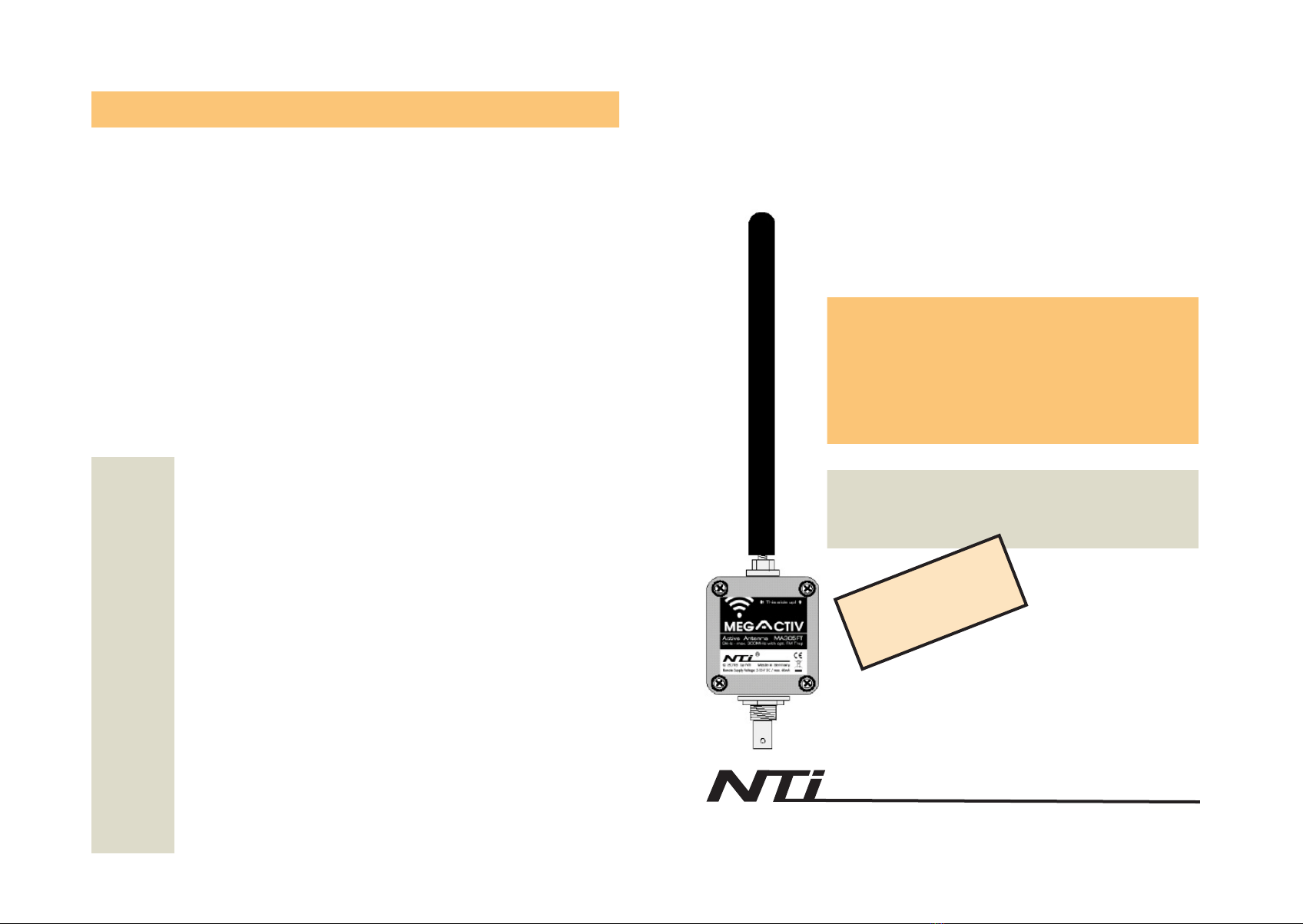
MegActiv
MA305FT
Active Antenna
9kHz - max. 300MHz
& FM-Trap
Operating Manual
Version V2.1
ATTENTION:
This is a receiving antenna!
Never connect it to a transmitter!
This will destroy the antenna electronics and
void the warranty.
Do not operate next to a transmitting antenna!
®

Attention:
If the red LED illuminates, disconnect the antenna and
power cables from the power inserter and investigate
the cause of the short circuit or overload!!
Operating principle
The MegActiv MA305FT is an active antenna with a maximum limit frequency of 300MHz, which responds
to the electrical component (E- eld) of the electromagnetic eld.
It has a very consistent, broadband frequency response in combination with vertically polarized all-round
reception characteristics and achieves good intermodulation values with low power consumption.
The power supply can be via an AC adapter or via USB (eg USB Power Bank). This makes it ideal
for portable use.
Switchable FM-Bandstop-Filter
Jumper FM trap (on /o ).
For attenuation of nearby
strong FM transmitters.
Default: O
Example for the outdoor installation
Coaxial power inserter
The antenna electronics are powered via the connected
coaxial cable of the power inserter. Power is supplied by
the power inserter (CPI 1500 UNI) which can be fed by
an external power supply. Whenever possible, do not
use a switch mode power supply; it is always preferable
to use a transformer.
Power can also be supplied via USB with
the optional
USB > DC power plug PartNo: 00163-1.
Do not use di erent
power supplies simultaneously! A self-resetting fuse will
limit the power input to 400mA in case of a short circuit.
The power inserter has two LED-status indicators:
Green (PWR): Operating voltage display
Red (!): Short-circuit or overload indicator
Inconspicuous
installation for
vertically polarized
omni-directional
reception.
Inside the antenna housing there is a jumper for
switching on an FM band-stop, if the MA305FT is
to be operated in the vicinity of an FM transmitter.
The FM band-stop attenuates the FM range (88-
108MHz) by typically 20dB and thus prevents clipping
or overload e ects and interference.
The installation of the antenna should ideally take place
outdoors, away from domestic electromagnetic noise.
Therefore, the antenna should be sited typically 5 to 10
meters distant from any building.
Contrary to widely held opinion, the highest possible
installation location is not always the best. Better near
the ground, mount on a mast that is 2m high. This
means that the antenna is less exposed to the risk
of lightning and at the same time cable resonance
e ects are avoided.
The coax cable used should have the highest
possible attenuation. We recommend the coax cable
types Hyper ex 5 (Messi&Paoloni) or H155 (Belden).
When using a metallic antenna mast, the coaxial
shielding should also be grounded near the antenna.
>>> max. 2m <<<
Seal the BNC socket!
Although BNC connectors are protected against splashing water, they must be sealed
outdoors with a self-vulcanizing sealing tape for permanent use! (e.g. Nittotape part
number: 00198). Otherwise, capillary action can result in water ingress into the
housing and damage the electronics. Such damage is therefore excluded from the
warranty! The antenna housing must always be mounted with the BNC socket facing
down!
Active Antenna Connection Scheme
Important Information:
• Inappropriate/incorrect use, modifi cations, damaged or removed seals
odi cations to the device, damaging any product warranty seals, barcodes, warnings or other stickers
will void the warranty and the right to return the product to the manufacturer.
• Power Supplies
Ensure that the voltage and polarity of the power supply are correct. For interference-free operation, do
not use a switch-mode power supply.
CAUTION: in extreme cases, simple unregulated transformer power supplies can deliver up to 1.4
times that of the stated output voltage. Therefore, wherever possible, use regulated analogue power
supplies.


