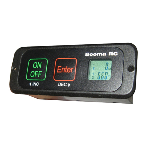
Booma-RC Wallaby Switch User manual

Wallaby Switch
Booma RC
1
www.boomarc.com

Congratulaons for choosing the Booma RC Wallaby Switch.
Wallaby Switch was designed for giant scale RC enthusiasts by
giant scale RC enthusiasts. Wallaby Switch oers features never
seen before in Radio Control applicaons in a compact, light
weight and aordable package.
Before you install Wallaby Switch please take the me
to read these instrucons. A few simple steps will
have you successfully using this advanced product in
no me at all.
Wallaby Switch Features:
- Microprocessor control - of high powered digital switching circuit(s) .
- Fail Safe Switching - of both baeries.
- High Bright Blue LED - for easy daylight reading.
- Voltage Monitoring - of each baery. (BRCWAL1 and 2 version)
- Selectable Baery Type - for monitoring of LifeP04, LiPo and Lion bat-
tery chemistries.
- Low Voltage Alarm via LED indicaon.
- 2 x 10 Amp constant current capability (Ultra Connecor version).
- 2 x 20 Amp for 30 seconds (Ultra Connecor version).
- Micro-Power design less than 0.4mA in standby mode.
- Input Voltage 6v to 13v.
- Weight 17 grams.
- Dimensions 36mm x 17mm (1.41 x 0.66 inches).
DO’S and DON’TS
Wallaby Switch comes with 1 or 2 completely independent solid
state digital switches and is designed to be used with 1 or 2 bat-
teries of the same chemistry and capacity for receiver and servo
switching. A matched pair of baeries will give best performance.
2

3
DO’S and DON’TS
DO NOT use Wallaby Switch dual baery version with baeries
of dierent voltages or dierent baery chemistries unless you
are an advanced user that is aware of the consequences. Mixing
of dierent baery voltages or chemistry types when using Wal-
laby Switch may cause the baery with the highest voltage to
be consumed rst. This may be desirable if you are experienced
with modeling or Robocs, however you do this at your own
risk.
It is recommended that Wallaby Switch dual baery version is
used in conjuncon with a Booma RC Dual Baery isolator for
baery fail-safe single receiver usage.
NEVER USE Wallaby Switch (OR ANY DUAL SWITCH) TO SWITCH
AN IGNITION SYSTEM AND RECEIVER SYSTEM AT THE SAME
TIME. INTERFERENCE FROM THE IGNITION SYSTEM MAY CAUSE
LOSS OF CONTROL OF YOUR MODEL.
To switch your models gas ignion system we recommend the
Booma RC Ignion (Iggy) Switch, designed to isolate any ignion
interference from your receiver system.
WARNING
Please observe correct connecon polarity i.e. RED is baery
posive and BLACK is baery negave. Incorrect polarity will
damage the main circuit output capacitor(s) voiding warranty.

Dual Baery and Dual Receiver System
Dual Baery Redundant System
Battery 1
Battery 2
Receiver 1
Receiver 2
Battery 1
Battery 2
Wallaby
Switch Input
Wallaby
Switch Input
Wallaby Switch
Built in
Dual Battery
Isolator circuit
Single Receiver
or
SmartBus
Typical Connecon Examples for
Wallaby Switch.
4
Single Baery System
Battery Wallaby
Switch Input
Receiver Servos
Wallaby
Switch Input
Wallaby
Switch Input
Wallaby Switch
Built in
Dual Battery
Isolator circuit

5
Lets get started
Connect both baeries to Wallaby Switch baery inputs as
shown below.
Baery Inputs Wallaby Switch Outputs
Wallaby Switch OutputsBaery Inputs
As you connect the baery or baeries to Wallaby Switch the
LED indicator will ash slowly THREE mes.
This indicates that all is OK.
If the LED starts to ash rapidly this is an indicaon of incorrect
baery type or a low voltage on one of the connected baeries.
We will discuss baery type and voltage monitoring further in
these instrucons.

ON
OFF Enter
Turning Wallaby Switch ON and OFF
To Switch Wallaby Switch ON (aer baery connecon is made)
PRESS AND HOLD the GREEN “ON/OFF” buon. The Blue LED
will start to FLASH rapidly up to 10 mes. While the LED is ash-
ing press the RED “ENTER” buon once and Wallaby Switch will
switch both baeries on supplying power.
To Switch Wallaby Switch OFF (Wallaby Switch must be in the on
posion) PRESS AND HOLD the GREEN “ON/OFF” buon.
The Blue LED will start to FLASH rapidly up to 10 mes.
While ashing press the RED “ENTER” buon and Wallaby Switch
will switch both baeries o removing power to the receiver(s).
Wallaby Switch is supplied with 1 or 2 x fail-safe switches (de-
pending on the selected model). As long as power is supplied
to Wallaby Switch it will hold the state of the switch. Wallaby
Switch also comes with addional protecon circuitry to avoid
an accidental ON or OFF state.
6

Sleep Mode
SLEEP MODE WILL ONLY ACTIVATE WHEN Wallaby Switch IS IN
THE OFF STATE
Wallaby Switch uses a state-of-the-art low power technology to
maximise the life of your baeries. While in the o state Wallaby
Switch will go into a sleep mode using only 0.4mA to conserve
power. You can leave Wallaby Switch connected to the baeries
however it is advisable to disconnect Wallaby Switch from the bat-
teries if storing your model for a long period.
WHAT HAPPENS IN SLEEP MODE?
To conserver power Wallaby Switch turns o all unnecessary cir-
cuits and blanks the LED to conserve baery power.
WAKING Wallaby Switch FROM SLEEP MODE.
In sleep mode Wallaby Switch is monitoring the front panel but-
tons. Wallaby Switch will automacally wake from sleep mode
when you press the press GREEN “ON/OFF” buon.
7
ON
OFF Enter

Template Cutout for Wallaby Switch
8
17 mm
36 mm

9
Baery selecon
IMPORTANT - DO NOT MIX BATTERY CHEMISTRY WHEN USING
Wallaby Switch. ALWAYS USE BATTERIES OF THE SAME CHEMIS-
TRY AND CAPACITY.
Wallaby Switch comes pre-calibrated to monitor voltage levels and
current consumpon of LiFeP04 chemistry baeries. If you are
using LiPo or Lion baeries you will need to re-calibrate Wallaby
Switch. Wallaby Switch is easy to calibrate.
How To Calibrate - connect both baeries to Wallaby Switch
and wait unl the system check is complete (three slow ashes).
Press and hold the RED “ENTER” buon. Aer a brief period the
LED will start to ash rapidly. While rapidly ashing, release the
RED “ENTER” buon. Depending on currently selected baery
chemistry the LED will then ash as follows:
LiFe monitoring Three ashes - pause - three ashes etc
Lion and Lipo One ash - pause - one ash etc
Pressing the RED “ENTER” buon or GREEN “ON/OFF” will cycle
through the dierent baery types. Once you have selected the
baery type to match your baeries just release the buon.
Wallaby Switch will automacally return back to normal mode
aer 4 ash cycles.

Baery Monitoring
Once you have calibrated Wallaby Switch with the correct bat-
tery type it will monitor the output voltage of your baery(s)
If a low voltage is seen by Wallaby Switch from either baery
then Wallaby Switch will ash the Blue LED in rapid bursts. This
is an indicaon that something is wrong and should be inves-
gated.
FACTS
Why does Wallaby Switch show a low voltage condion when I
switch on even if I have selected the correct baery type?
This could be and indicaon that one of the cells in a baery is go-
ing bad. Test and if necessary replace the poor baery.
This could also be an indicaon that you are using baeries of
insucient capacity i.e. the baery does not have the ability to
output the required power without a signicant voltage drop.
Install a more powerful baery.
Connecng the outputs of Wallaby Switch together.
This will work ne in a single receiver/Cybuss system (as long as
the baeries are the same chemistry and cell count). Be aware
though that the baery with the highest voltage will supply the
load to the receiver/servos and try to balance the 2 baeries.
Think of 2 buckets of water, each bucket lled slightly dierently.

11
If you connect the 2 buckets with a hose then the bucket with
higher water level will try to ll the bucket with the lower water
level unl they are equal. It is the same with baeries and this is
why we should always use the same baery type and cell count
when connecng the outputs of Wallaby Switch together.
Using Wallaby Switch with a Booma RC DUAL-BAT circuit.
The Dual-Bat circuit allows you to safely connect the 2 Wallaby
Switch outputs together, eecvely isolang the baeries from
each other. In a single receiver setup a Dual Bat circuit is a great
idea. The Wallaby Switch internal microprocessor circuit uses an
internal micro Dual Bat circuit to guarantee supply to the Wallaby
Switch microprocessors.
Baery Capacity
DO NOT EVER try to get the full mA capacity out of your baeries!
An aempt to do this may end in disaster. Wallaby Switch meters
consumpon conservavely but NEVER OPERATE YOUR MODEL
WITH A LOW VOLTAGE CONDITION.
Current carrying capacity of connectors.
Wallaby Switch will handle 15A per circuit (30A total). However,
JR or Futaba type servo connectors are designed to carry a maxi-
mum of approximately 5 Amps per connector. This is sucient
for most RC models up to 9 servos. If your model has more than
9 servos it is recommended to use a deans style ultra connector.

Template Cutout for Wallaby Switch
12
17 mm
36 mm

13
Current capacity will then be limited to Wallaby Switch design.
Using Wallaby Switch with a voltage regulator
Wallaby Switch was designed to work with all current RC products
regulated and unregulated. If you prefer using LifeP04 chemistry
baeries (nominal 6.4v) then Wallaby Switch will work excellently
in most RC and Robocs applicaons without a regulator.
If you prefer to use newer higher 7.2 volt servos then we rec-
ommend using Wallaby Switch with Lion (nominal 8.2v) or Lipo
baeries (nominal 8.4v). These baeries will in most cases require
a voltage regulator like the Booma RC Intelli-Reg, Regulator-Pro
or Helli-Reg Pro. These regulators have been designed to deliver
professional results for the most discerning hi-end user. Wallaby
Switch may also be used with all other types of regulators and
power buss circuits.

Specicaons
- 2 x independent switching circuits in a double pole single throw
combinaon.
- Baery chemistry
LifeP04 (2 - 3 cells),
LiPo Life (2 - 3 cells),
Lion (2 - 3 cells).
- Maximum input voltage 13 volts.
- Minimum input voltage 6 volts
- Max connuous current:
2 x 10 Amp (20 Amp),
2 x 20 Amp (40 Amp for 30 sec),
- Max instantaneous current 2 x 30 Amp.
- Weight 17 grams.
- Approximately 0.4 mA current draw in power-down mode.
- Length 36 mm x width 17 mm x Depth 17 mm
- Operang Temperature - 40 to 80 degrees Celsius
12 Month Replacement Warranty
Booma RC will replace this product within 12 months if found to
be defecve in material and/or workmanship when used in the
intended purpose. The warranty does not cover - Shipping charges
related to any warranty claim. An over voltage or over current
usage beyond stated specicaon. Damage due to system failure,
negligence, abuse, accident, improper installaon or freezing.
Loss of me, inconvenience, loss of model, or other incidental or
consequenal damages.
14

Booma RC Ignion (Iggy) Switch
Booma RC Intelliswitch
Booma RC DualBat

Notes
Table of contents
Other Booma-RC Switch manuals
Popular Switch manuals by other brands
Endress+Hauser
Endress+Hauser Solicap M FTI55 operating instructions

Gefen
Gefen ex-tend-it 4x4 DVI Matrix user manual
See Water
See Water Oil Smart OSS20R6 quick start guide
CyberData
CyberData 011539 Installation quick reference
Siemens
Siemens Type Vector instruction manual
Stealth Products
Stealth Products i-Connect 5 owner's manual
