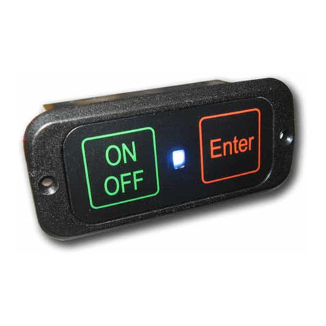
Booma-RC Hidden Ignition Switch User manual

Hidden Ignion Switch
Booma RC
1
www.boomarc.com

Congratulaons for choosing the Booma RC Hidden Ignion
Switch.
This switch is the result of feedback from our company pilots and
was designed for giant scale RC enthusiasts by a giant scale RC
enthusiast. The hiddend switch is the world’s rst 2 stage fail safe
ignion switch in a compact and aordable package.
Before you install the hidden switch please take the
me to read these instrucons. A few simple steps
will have you successfully using this advanced product
in no me at all.
Features:
- Microprocessor control - of Opcal Isolated digital switching circuit.
- Fail Safe Switching - follows fail safe switching of receiver setup.
- High Bright Blue LED - for easy daylight viewing.
- 2 Stage Arming - for complete monitoring of potenal live ignion.
- 2 Stage Emergency Ignion Kill -
By transmier signal.
By switching o power to the receiver.
- Remote Ignion Kill - via transmier.
- Receiver Power connected Indicaon - via LED ashing indicaon.
- Micro-Power design less than 1uA in standby mode. Less drain on your
model’s ignion baery than baery leakage so you can leave The Hidden
Ignion Switch connected to the ignion baery permanently.
- Baery Input Voltage 1v to 60v.
- Can also be used as an “On-board” Glow Driver.
- Weight 17 grams.
2

Typical Connecon Examples for
The Hidden Ignion Switch .
Ignition
Battery
Ignition
switch
Receiver
Ignition
On Board
Glow
Battery
Ignition
Switch
Receiver
Glow Plug
As a Gas powered Ignion switch
As an “On Board” Glow switch
3

Lets get started
Connect as shown above.
The ignion switch’s microprocessor draws it’s power from
your receiver and is only in awake state while your receiver is
switched on. Switching o power to your receiver will put the
switch to sleep and kill the ignion.
The hidden ignion switch does not need to be connected to the
Ignion/glow baery for system set up so it is recommended to
connect only to your model’s receiver for setup.
4
Baery input
Baery input
To Ignion
To Ignion
Connecon to
Receiver Channel
Lead Connecon Examples for The
Hidden Ignion Switch .

5
PLEASE NOTE: One of the safety features is that The Hidden Igni-
on Switch draws it’s power from your models’ receiver so The
Hidden Ignion Switch is completely inoperable unless connect-
ed to your model’s receiver and the receiver is powered up!
The Hidden Ignion Switch also requires one receiver channel to
operate and is set to switch at approximately 50% of sck posi-
on. It is recommended to connect The Hidden Ignion Switch
to a switch channel on your receiver and adjust the switch unl
The Hidden Ignion Switch operates as required. Seng up a
transmier for switching will dier for each transmier type so
please refer to your transmier manual for switch channel set-
ng.
FOR THE TECHNICALLY MINDED ONLY
The Hidden Ignion Switch has a dead-band where neither an
On or O state is acve. This funconality is built into The Hid-
den Ignion Switch so that Switch uer cannot happen.
Also a bad signal (no pulse or less than 50% mark space rao)
must be present for more than 20 connuous frames before The
Hidden Ignion Switch will kill the ignion. In most modern re-
ceivers fail safe is built in so this condion should never be met
except as a complete system safety feature.
This dead band feature comes at a cost of a small delay (approxi-
mately 500 - 600 milliseconds) in switching ON/OFF.
PLEASE NOTE
Please observe correct connecon polarity i.e. RED is baery
posive and BLACK is baery negave.
An Incorrect polarity connecng will not allow your baery to
supply power to the Ignion.

Turning The
Hidden Ignion Switch ON
Aer connecng The Hidden Ignion Switch (as shown on page
4) turn on the model’s receiver, The Hidden Ignion Switch will
start to ash slowly. This is an indicaon that receiver power is
being supplied to The Hidden Ignion Switch .
While the Blue LED is ashing.
If you have adjusted your receiver channel correctly, switching on
the selected transmier switch/channel will arm The Hidden Igni-
on Switch (Ignion state is on) and the LED will be permanently
lit. If the blue LED does not light up permanently then you will
need to adjust your transmier. Please refer to your transmier
instrucon manual.
HINT use a sck channel (moving the sck up down or le right)
to verify The Hidden Ignion Switch ’s arming funcon (Blue
LED permanently On) and then once sased all is well move
The Hidden Ignion Switch to a switch channel on your models
receiver.
6

7
Turning The Hidden Ignion Switch
OFF
The Hidden Ignion Switch can disarm your models ignion
system using 3 methods.
1) Normal Mode - Switch o via the transmier. Approximately
0.5 of a second to switch o. Then switch o the receiver power.
2) EMERGENCY Mode (all else fails) switch o the receiver’s
power.
No maer what mode you use The Hidden Ignion Switch will
be ready to react to your command.

8
FACTS
Why does The Hidden Ignion Switch turn OFF when I switch
to a turn on condion via my transmier? The Hidden Ignion
Switch is designed to switch on from a pulse width greater that
50%. Reverse the switch condion on your transmier will set it
right.
Can I use The Hidden Ignion Switch as a General Purpose Op-
cally Isolated switch i.e not as an ignion switch? Yes you can,
The Hidden Ignion Switch can be used for any general purpose
funcon as long as the maximum recommended voltage (60V) and
current draw (4A or 6A) is observed.
Current carrying capacity of connectors - The Hidden Ignion
Switch will handle up to 4A current on the baery/ignion circuit
so a JR type connector is more than adequate for most uses. If a
higher current rang is required we also oer The Hidden Ignion
Switch in a 6A version with Ultra connectors. Current capacity will
then be limited to The Hidden Ignion Switch design.
Using The Hidden Ignion Switch with a voltage regulator - The
Hidden Ignion Switch was designed to work with all current RC
products regulated and unregulated. If you prefer using LifeP04
chemistry baeries (nominal 6.4v) then The Hidden Ignion
Switch will work excellently in most RC Ignion applicaons with-
out a regulator.

9
Specicaons
- Opcal Isolated digital switching circuit with beer than 1500V
Isolaon.
- Works with Baery chemistry
LifeP04 (2 cells) In most cases a regulator not required.
LiPo (2 cells) Ignion may require a regulator.
Lion (2 cells) Ignion may require a regulator.
NiCd (5 Cells) Ignion no regulator required.
NiMH (5 Cells) Ignion no regulator required.
NiCd (1 Cell) Glow Driver.
NiMH (1 Cell) Glow Driver.
- Maximum input voltage 60 volts.
- Minimum input voltage 1 volt. (Ideal also for glow driver)
- Max connuous current: 4A or 6A depending on version
- Weight 17 grams.
- Approximately 1uA current draw from ignion baery.
- Length 36 mm x width 17 mm x Depth 17 mm
- Operang Temperature - 40 to 80 degrees Celsius
12 Month Replacement Warranty
Booma RC will replace this product within 12 months if found to
be defecve in material and/or workmanship when used in the
intended purpose. The warranty does not cover - Shipping charges
related to any warranty claim. An over voltage or over current
usage beyond stated specicaon. Damage due to system failure,
negligence, abuse, accident, improper installaon or freezing.
Loss of me, inconvenience, loss of model, or other incidental or
consequenal damages.

Booma RC Wallaby Switch
Booma RC Intelliswitch
Booma RC DualBat
10

11
Notes

12
Notes

13
Notes

14
Notes

15
Notes

Notes
16
Table of contents
Other Booma-RC Switch manuals
Popular Switch manuals by other brands
Endress+Hauser
Endress+Hauser Solicap M FTI55 operating instructions
Gefen
Gefen ex-tend-it 4x4 DVI Matrix user manual
See Water
See Water Oil Smart OSS20R6 quick start guide
CyberData
CyberData 011539 Installation quick reference
Siemens
Siemens Type Vector instruction manual
Stealth Products
Stealth Products i-Connect 5 owner's manual
