Bopp & Reuther Vortex VTX3 K i Ex Wiring diagram

VTX3
VTX3VTX3
VTX3 Supplementary Instructions
Supplementary InstructionsSupplementary Instructions
Supplementary Instructions
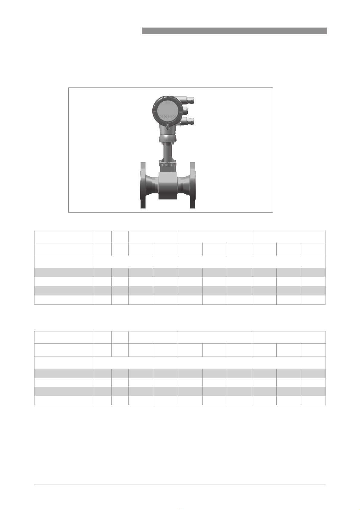
Vortex flowmeter
Equipment category II 2 G, EPL Gb
in protection type intrinsic safety "i"
© Bopp & Reuther Messtechnik GmbH 12/2018 - Z-EN-09001-id-A Exi-Gb

CONTENTS
2
www.bopp-reuther.de 12/2018 - Z-EN-09001-id-A Exi-Gb
VTX3
1 Safety instructions 3
1.1 General notes ................................................................................................................... 3
1.2 EU conformity ................................................................................................................... 3
1.3 Safety instructions............................................................................................................ 3
2 Device description 4
2.1 Device description ............................................................................................................ 4
2.2 Type code .......................................................................................................................... 4
2.3 Marking............................................................................................................................. 5
2.4 Flammable products ........................................................................................................ 7
2.5 Equipment category .........................................................................................................7
2.6 Types of protection ........................................................................................................... 8
2.7 Ambient temperature / temperature classes.................................................................. 8
2.8 Electrical data................................................................................................................. 16
3 Installation 17
3.1 Mounting ......................................................................................................................... 17
3.2 Special conditions........................................................................................................... 18
4 Electrical connections 19
4.1 General notes ................................................................................................................. 19
4.2 Power supply .................................................................................................................. 19
4.3 Inputs / Outputs .............................................................................................................. 20
4.4 Grounding and equipotential bonding............................................................................ 20
4.5 Flow sensor circuits (remote version only) ................................................................... 22
5 Operation 23
5.1 Start-up........................................................................................................................... 23
5.2 Operation ........................................................................................................................ 23
5.3 Electrostatic charge .......................................................................................................23
6 Service 24
6.1 Maintenance ................................................................................................................... 24
6.2 Dismantling .................................................................................................................... 24
7 Notes 26

SAFETY INSTRUCTIONS
1
3
VTX3
www.bopp-reuther.de12/2018 - Z-EN-09001-id-A Exi-Gb
1.1 General notes
This additional instruction applies to explosion-protected versions of vortex flowmeters with
protection type intrinsic safety "i", equipment category II 2 G and EPL Gb.
It completes the standard manual for the non-explosion protected versions.
The information given in this instruction contains only the data relevant to explosion protection.
The technical details given in the manual for the non-explosion protected versions remain
unchanged unless they will be excluded or replaced by this instruction.
1.2 EU conformity
The manufacturer declares with the EU declaration of conformity on his own responsibility
conformity with the protection goals of directive 2014/34/EU for use in hazardous areas with gas.
The EU declaration of conformity for the equipment category II 2 G is based on the EU type
examination certificate of the KIWA ExVision:
The "X" after the certificate number refers to special conditions for safe use of the device, which
have been listed in these instructions.
1.3 Safety instructions
If these instructions are not followed, there is a risk of explosion.
Assembly, installation, start-up and maintenance may only be performed by personnel trained in
explosion protection!
KIWA 18 ATEX 0041X
KIWA 18 ATEX 0041XKIWA 18 ATEX 0041X
KIWA 18 ATEX 0041X
CAUTION!
The operator or his agent is responsible for observing any additional standards, directives or
laws if required due to operating conditions or place of installation.
This applies in particular to the use of easily detachable process connections when measuring
flammable media.

2
DEVICE DESCRIPTION
4
VTX3
www.bopp-reuther.de 12/2018 - Z-EN-09001-id-A Exi-Gb
2.1 Device description
Vortex flowmeters measure and display the flow of flammable and non-flammable gases and
liquids. The signal converter includes either a 4...20 mA signal output with optional HART
®
communication or a bus connection. There are bus connections available according to the FISCO
model for connecting to the Foundation Fieldbus or Profibus PA. Signal converters with signal
output have a separate binary output and a separate current input.
The VTX3 W remote version consists of the SV18 flow sensor and the KV18 ..i-Ex signal converter.
2.2 Type code
The safety description code consists of the following elements*:
The remote version consisting of the flow sensor SV 18 and the signal converter KV 18 020 is
called the VTX3 W.
Figure 2-1: Safety description code for the compact version
1 Product designation
2 Type series
3 Compact version
4 Electrical signal output
free - current output 4...20 mA with optional HART
®
communication
FF - Foundation Fieldbus bus connection
PA - Profibus PA bus connection
5 Intrinsically safe supply
6 Ex - explosion-protected version
Figure 2-2: Safety description code for the signal converter of the remote version
1 Product designation
2 Type series
3 Remote version
4 Electrical signal output
free - current output 4...20 mA with optional HART
®
communication
FF - Foundation Fieldbus bus connection
PA - Profibus PA bus connection
5 Intrinsically safe supply
6 Sensor electronics VFC 020
7 Ex - explosion-protected version
Figure 2-3: Safety description code for the flow sensor of the remote version
1 Product designation
2 Type series of flow sensor

DEVICE DESCRIPTION
2
5
VTX3
www.bopp-reuther.de12/2018 - Z-EN-09001-id-A Exi-Gb
2.3 Marking
The marking of the devices in accordance with the description code is shown on the nameplates
below. On both the compact devices and the remote versions, the main plate is located on the
signal converter housing. On the remote versions there is an additional marking on the flow
sensor.
Compact versions with two signal converters for dual measurement (dual version) are each
marked with a nameplate, which is attached to each of the signal converter housings.
The details relevant to explosion protection are identical on both nameplates.
Figure 2-4: Example of a nameplate for the compact version
1 Device version VT3X K
2 Production order number
3 Serial number
4 Year of manufacture
5 Ex data according to KIWA 18 ATEX 0041X
6 Permissible ambient temperature range
7 Maximum values intrinsically safe circuits
8 Safety instructions, disposal and data matrix
9 Internet address of the manufacturer

2
DEVICE DESCRIPTION
6
VTX3
www.bopp-reuther.de 12/2018 - Z-EN-09001-id-A Exi-Gb
Figure 2-5: Example of the nameplates for the remote version
1 Device version VT3X W
2 Production order number
3 Serial number
4 Year of manufacture
5 Ex data according to KIWA 18 ATEX 0041X
6 Permissible ambient temperature range
7 Maximum values intrinsically safe circuits
8 Safety instructions, disposal and data matrix
9 Internet address of the manufacturer

DEVICE DESCRIPTION
2
7
VTX3
www.bopp-reuther.de12/2018 - Z-EN-09001-id-A Exi-Gb
2.4 Flammable products
Atmospheric conditions:
Atmospheric conditions:Atmospheric conditions:
Atmospheric conditions:
The standard atmospheric conditions under which it may be assumed that Ex equipment can be
operated are:
•Temperature: -20...+60°C / -4...+140°F
•Pressure: 80...110 kPa (0.8...1.1 bar) / 11.6...15.9 psi
•Air with normal oxygen content, typically 21%v/v
Ex equipment operating outside the standard temperature range must be tested and certified
(e.g. for ambient temperature range -40...+65°C / -40...+149°F).
Ex equipment operating outside the standard atmospheric pressure range and standard oxygen
content is not permitted.
Operating conditions:
Operating conditions:Operating conditions:
Operating conditions:
Vortex flowmeters operate outside the standard atmospheric pressure range, which means that
explosion protection, regardless of the zone assignment, is fundamentally not applicable for the
measuring unit (piping).
2.5 Equipment category
Vortex flowmeters are designed in category II 2 G and EPL Gb according to EN 60079-0 and
EN 60079-11 for use in zone 1. The inside of the measuring unit is also approved for zone 1.
CAUTION!
Operation with flammable products is only permitted as long as no explosive fuel/air mixture
builds up inside of the piping at the same time the atmospheric conditions are exceeded.
The operator is responsible to ensure that the flowmeter is operated safely in terms of the
temperature and pressure of the products used. In case of operation with flammable products
the measuring units must be included in the periodic pressure tests of the piping.
Definition of zone 1 according to EN 1127-1, Appendix B:
An area in which an explosive atmosphere, as a result of the mixture of flammable substances in
the form of gas, steam or mist with air, under normal operation may occasionally occur.

2
DEVICE DESCRIPTION
8
VTX3
www.bopp-reuther.de 12/2018 - Z-EN-09001-id-A Exi-Gb
2.6 Types of protection
2.7 Ambient temperature / temperature classes
Because of the influence of the temperature of the product, no fixed temperature class is
assigned to vortex flowmeters. The temperature class of these devices is rather a function of the
product temperature and ambient temperature that is present and the specific device version.
The classification is outlined in the following tables.
The tables take into account the following parameters:
•Ambient temperature T
amb
•Product temperature T
m
•Nominal size DN
•Heat resistance of the connecting cable
The marking is:
ATEX II 2 G Ex ia IIC T6...T2 Gb
II 2 G Ex ia IIC T6...T2 GbII 2 G Ex ia IIC T6...T2 Gb
II 2 G Ex ia IIC T6...T2 Gb
(compact version, flow sensor in remote version)
or
II 2 G Ex ia IIC T6 Gb
II 2 G Ex ia IIC T6 GbII 2 G Ex ia IIC T6 Gb
II 2 G Ex ia IIC T6 Gb
(signal converter in remote version)
The marking contains the following information:
The marking contains the following information:The marking contains the following information:
The marking contains the following information:
II
IIII
II Explosion protection, group II
2
22
2Equipment category 2
G
GG
GGas explosion protection
Ex ia
Ex iaEx ia
Ex ia Intrinsically safe, level of protection "ia"
IIC
IICIIC
IIC Gas group, suitable for gas groups IIC, IIB and IIA
T6...T2
T6...T2T6...T2
T6...T2 Temperature class range
(compact version, flow sensor in remote version)
T6
T6T6
T6 Temperature class
(signal converter in remote version)
Gb
GbGb
Gb EPL, suitable for zone 1
In principle, operation is possible in all ranges of the temperature classes T1...T6.

DEVICE DESCRIPTION
2
9
VTX3
www.bopp-reuther.de12/2018 - Z-EN-09001-id-A Exi-Gb
The permitted ambient temperature range is indicated on the nameplate; depending on the
device version it is T
amb
= -40...+65°C / -40...+149°F.
The minimum product temperature is -40°C/-40°F.
The maximum permissible product temperatures listed in the tables are valid under
the following conditions:
•
The measuring device is installed and operated in accordance with the manufacturer's
installation instructions.
•
It must be ensured that the flowmeter is not heated by the effects of additional heat radiation
(sunshine, neighbouring system components) and thus operated above the permissible
ambient temperature range.
•
Insulation must be limited to the piping. Unobstructed ventilation of the signal converter
must be ensured.
2
DEVICE DESCRIPTION
10
VTX3
www.bopp-reuther.de 12/2018 - Z-EN-09001-id-A Exi-Gb
Max. permissible product and ambient temperatures with signal converter or
connection box mounted above the flow sensor
Temperature class in °C
Temperature class in °F
Temperature class T6 T5 T4 T3 T2
T
amb
in °C40 60 60 65 40 60 65 40 60 65
Nominal size
DN15…25 85 65 135 135 1 200 200 1 185 1 240 210 1 185 1
DN40…50 75 65 135 135 1 200 195 1 165 1 240 195 1 165 1
DN80…100 70 65 135 1 135 1 200 165 1 145 1 240 1 165 1 145 1
DN150...300 80 65 135 135 1 200 200 1 170 1 240 200 1 170 1
1Permanent service temperature of connecting cable and cable entry min. 80°C
Temperature class T6 T5 T4 T3 T2
T
amb
in °F104 140 140 149 104 140 149 104 140 149
Nominal size
DN15…25 185 149 275 275 1 392 392 1 365 1 464 410 1 365 1
DN40…50 167 149 275 275 1 392 383 1 329 1 464 383 1 329 1
DN80…100 158 149 275 1 275 1 392 329 1 293 1 464 1 329 1 293 1
DN150...300 176 149 275 275 1 392 392 1 338 1 464 392 1 338 1
1Permanent service temperature of connecting cable and cable entry min. 176°F

DEVICE DESCRIPTION
2
11
VTX3
www.bopp-reuther.de12/2018 - Z-EN-09001-id-A Exi-Gb
Max. permissible product and ambient temperatures with signal converter or
connection box mounted at side or underneath the flow sensor
Temperature class in °C
Temperature class in °F
Temperature class T6 T5 T4 T3 T2
T
amb
in °C40 60 60 65 40 60 65 40 60 65
Nominal size
DN15…25 85 90 135 135 200 200 200 1 240 240 240 1
DN40…50 85 80 135 135 200 200 200 1 240 240 240 1
DN80…100 85 75 135 135 1 200 200 1 200 1 240 240 1 240 1
DN150...300 85 80 135 135 200 200 200 1 240 240 240 1
1Permanent service temperature of connecting cable and cable entry min. 80°C
Temperature class T6 T5 T4 T3 T2
T
amb
in °F104 140 140 149 104 140 149 104 140 149
Nominal size
DN15…25 185 194 275 275 392 392 392 1 464 464 464 1
DN40…50 185 176 275 275 392 392 392 1 464 464 464 1
DN80…100 185 167 275 275 1 392 392 1 392 1 464 464 1 464 1
DN150...300 185 176 275 275 392 392 392 1 464 464 464 1
1Permanent service temperature of connecting cable and cable entry min. 176°F
2
DEVICE DESCRIPTION
12
VTX3
www.bopp-reuther.de 12/2018 - Z-EN-09001-id-A Exi-Gb
Max. permissible product and ambient temperatures for devices with painted flow
sensors / signal converters or connection box mounted above the flow sensor
Temperature class in °C
Temperature class in °F
Temperature class T6 T5 T4 T3 T2
T
amb
in °C40 60 60 65 40 60 65 40 60 65
Nominal size
DN15…25 60 60 120 1 120 1 120 120 1 120 1 120 120 1 120 1
DN40…50 55 60 120 1 115 1 120 120 1 115 1 120 120 1 115 1
DN80…100 55 60 110 1 105 1 120 110 1 105 1 120 110 1 105 1
DN150...300 60 60 120 1 115 1 120 120 1 115 1 120 120 1 115 1
1Permanent service temperature of connecting cable and cable entry min. 80°C
Temperature class T6 T5 T4 T3 T2
T
amb
in °F104 140 140 149 104 140 149 104 140 149
Nominal size
DN15…25 140 140 248 1 248 1 248 248 1 248 1 248 248 1 248 1
DN40…50 131 140 248 1 239 1 248 248 1 239 1 248 248 1 239 1
DN80…100 131 140 230 1 221 1 248 230 1 221 1 248 230 1 221 1
DN150...300 140 140 248 1 239 1 248 248 1 239 1 248 248 1 239 1
1Permanent service temperature of connecting cable and cable entry min. 176°F
DEVICE DESCRIPTION
2
13
VTX3
www.bopp-reuther.de12/2018 - Z-EN-09001-id-A Exi-Gb
Max. permissible product and ambient temperatures for devices with painted flow
sensors / signal converters or connection box mounted at side or underneath the flow
sensor
Temperature class in °C
Temperature class in °F
Temperature class T6 T5 T4 T3 T2
T
amb
in °C40 60 60 65 40 60 65 40 60 65
Nominal size
DN15…25 85 65 120 120 1 120 120 120 1 120 120 120 1
DN40…50 70 65 120 1 120 1 120 120 1 120 1 120 120 1 120 1
DN80…100 70 65 120 1 120 1 120 120 1 120 1 120 120 1 120 1
DN150...300 75 65 120 120 1 120 120 120 1 120 120 120 1
1Permanent service temperature of connecting cable and cable entry min. 80°C
Temperature class T6 T5 T4 T3 T2
T
amb
in °F104 140 140 149 104 140 149 104 140 149
Nominal size
DN15…25 185 149 248 248 1 248 248 248 1 248 248 248 1
DN40…50 158 149 248 1 248 1 248 248 1 248 1 248 248 1 248 1
DN80…100 158 149 248 1 248 1 248 248 1 248 1 248 248 1 248 1
DN150...300 167 149 248 248 1 248 248 248 1 248 248 248 1
1Permanent service temperature of connecting cable and cable entry min. 176°F

2
DEVICE DESCRIPTION
14
VTX3
www.bopp-reuther.de 12/2018 - Z-EN-09001-id-A Exi-Gb
Max. permissible product and ambient temperatures with signal converter in stainless
steel (bright) or connection box in stainless steel (bright) mounted above the flow
sensor
Temperature class in °C
Temperature class in °F
Temperature class T6 T5 T4 T3 T2
T
amb
in °C40 60 60 65 40 60 65 40 60 65
Nominal size
DN15…25 70 60 135 135 1 200 180 1 155 1 225 180 1 155 1
DN40…50 65 60 135 1 135 1 200 160 1 140 1 235 160 1 140 1
DN80…100 60 60 135 1 125 1 200 1 140 1 125 1 200 1 140 1 125 1
DN150...300 65 60 135 1 135 1 200 165 1 145 1 220 165 1 145 1
1Permanent service temperature of connecting cable and cable entry min. 80°C
Temperature class T6 T5 T4 T3 T2
T
amb
in °F104 140 140 149 104 140 149 104 140 149
Nominal size
DN15…25 158 140 275 275 1 392 356 1 311 1 437 356 1 311 1
DN40…50 149 140 275 1 275 1 392 320 1 284 1 455 320 1 284 1
DN80…100 140 140 275 1 257 1 392 284 1 257 1 392 1 284 1 257 1
DN150...300 149 140 275 1 275 1 392 329 1 293 1 428 329 1 293 1
1Permanent service temperature of connecting cable and cable entry min. 176°F

DEVICE DESCRIPTION
2
15
VTX3
www.bopp-reuther.de12/2018 - Z-EN-09001-id-A Exi-Gb
Max. permissible product and ambient temperatures with signal converter in stainless
steel (bright) or connection box in stainless steel (bright) mounted at side or
underneath the flow sensor
Temperature class in °C
Temperature class in °F
Temperature class T6 T5 T4 T3 T2
T
amb
in °C40 60 60 65 40 60 65 40 60 65
Nominal size
DN15…25 85 60 135 135 200 200 200 1 240 240 240 1
DN40…50 85 60 135 135 1 200 200 200 1 240 240 1 225 1
DN80…100 85 60 135 135 1 200 200 1 200 1 240 240 1 225 1
DN150...300 85 60 135 135 200 200 200 1 240 240 240 1
1Permanent service temperature of connecting cable and cable entry min. 80°C
Temperature class T6 T5 T4 T3 T2
T
amb
in °F104 140 140 149 104 140 149 104 140 149
Nominal size
DN15…25 185 140 275 275 392 392 392 1 464 464 464 1
DN40…50 185 140 275 275 1 392 392 392 1 464 464 1 437 1
DN80…100 185 140 275 275 1 392 392 1 392 1 464 464 1 437 1
DN150...300 185 140 275 275 392 392 392 1 464 464 464 1
1Permanent service temperature of connecting cable and cable entry min. 176°F

2
DEVICE DESCRIPTION
16
VTX3
www.bopp-reuther.de 12/2018 - Z-EN-09001-id-A Exi-Gb
2.8 Electrical data
Signal circuits
Signal circuitsSignal circuits
Signal circuits
The vortex flowmeter signal circuits may only be connected to separate, certified, intrinsically
safe isolating amplifiers or zener barriers connected to separate, intrinsically safe circuits with
the following maximum values per circuit:
Flow sensor circuits
Flow sensor circuitsFlow sensor circuits
Flow sensor circuits
For the compact versions, the intrinsically safe flow sensor circuits are designed as internal
circuits.
For the remote versions, the intrinsically safe flow sensor circuits are led through.
The maximum permissible safety values of the flow sensor circuits are listed below:
Remote signal converter, flow sensor circuit (terminal 1 to 7, colour-coded)
Remote signal converter, flow sensor circuit (terminal 1 to 7, colour-coded)Remote signal converter, flow sensor circuit (terminal 1 to 7, colour-coded)
Remote signal converter, flow sensor circuit (terminal 1 to 7, colour-coded)
U
o
=6.65V;I
o
= 1107 mA; P
o
= 650 mW; C
o
=1.5µF; L
o
=73µH
Remote flow sensor (terminal 1 to 7, colour-coded)
Remote flow sensor (terminal 1 to 7, colour-coded)Remote flow sensor (terminal 1 to 7, colour-coded)
Remote flow sensor (terminal 1 to 7, colour-coded)
U
i
=7V;I
i
= 1107 mA; P
i
= 650 mW; C
i
=0;L
i
=0
Device version Circuit
Terminals
Maximum values
U
i
[V] I
i
[mA] P
i
[W] C
i
[nF] L
i
[μH]
VTX3 K i Ex
VTX3 W i Ex
Current output 4...20 mA
C1, C2 30 130 110 ~ 0
Binary output
M1, M2, M3, M4 30 100 110 ~ 0
Current input
I1, I2 30 130 115 ~ 0
VTX3 K FF i Ex
VTX3 W FF i Ex FF / Entity Model I.S.
A1, A2
B1, B2
24 250 1.2 ~ 0 ~ 0
FF / FISCO
A1, A2
B1, B2
17.5 380 5.32 ~ 0 ~ 0
FISCO FIELD DEVICE
VTX3 K PA i Ex
VTX3 W PA i Ex FISCO
A1, A2
B1, B2
24 380 5.32 ~ 0 ~ 0
FISCO FIELD DEVICE
The verification of intrinsic safety for the interconnection between the flow sensor an the signal
converter is not necessary, if the cable length does not exceed 50 m / 164 ft and the supplied
cable is used.

INSTALLATION
3
17
VTX3
www.bopp-reuther.de12/2018 - Z-EN-09001-id-A Exi-Gb
3.1 Mounting
Mounting and setup must be carried out according to the applicable installation standards
(e.g. EN 60079-14) by qualified personnel trained in explosion protection.
The information given in the manual and these instructions must always be observed.
Vortex flowmeters must be installed in such a way that
•no external forces are affecting the indication unit.
•the device is accessible for any necessary visual inspections and can be viewed from all sides.
•the nameplate is clearly visible.
•it can be operated from a location with secure footing.
Aligning the signal converter
The signal converter and the connection box for the remote versions may be aligned on the base
or the wall bracket up to a maximum of ±180 . For this reason, the M4 hexagon socket screw
connecting the base and the signal converter or the connection box must be loosened. Once the
signal converter or the connection box has been turned, it must be screwed back on to the base
again (tightening torque 2 Nm).
• De-energise the signal converter.
• Loosen the hexagon socket screw 1.
• Turn the signal converter or the connection box.
• Screw signal converter or connection box back to the base again.
CAUTION!
The manufacturer is not liable for any damage resulting from improper use or use other than the
intended purpose. This applies in particular to hazards due to insufficient corrosion resistance
and suitability of the materials in contact with product.
Figure 3-1: Aligning the signal converter
1 M4 hexagon socket screw on connection housing

3
INSTALLATION
18
VTX3
www.bopp-reuther.de 12/2018 - Z-EN-09001-id-A Exi-Gb
3.2 Special conditions
Electrostatics
If the installation takes place in hazardous areas of group IIC, the instructions for electrostatics
must be observed. For further information refer to
Electrostatic charge
on page 23.
Thermal and electrical data
Observe the maximum ambient and product temperatures and electrical data. For further
information refer to
Ambient temperature / temperature classes
on page 8 and refer to
Electrical data
on page 16.

ELECTRICAL CONNECTIONS
4
19
VTX3
www.bopp-reuther.de12/2018 - Z-EN-09001-id-A Exi-Gb
4.1 General notes
The separate intrinsically safe signal circuits are electrically connected in the terminal
compartment of the signal converter. The circuits are designed in protection type "intrinsically
safe" and galvanically isolated from ground (test voltage ≥500 V
eff
).
The intrinsically safe flow sensor circuits are connected in the connection boxes on the wall
bracket and on the flow sensor.
The connecting cables should be selected according to the applicable installation standards
(e.g. EN 60079-14) and the maximum operating temperature.
The connecting cable between the flow sensor and the wall bracket for remote versions is part of
the supply.
•The connecting cables must be fixed and laid so they are sufficiently protected against
damage.
•All cores that are not used must be securely connected to the ground potential of the
hazardous area or carefully insulated against each other and against ground (test voltage
≥500 V
eff
).
•Lay cables so as to ensure that there is sufficient distance between surfaces of the flow
sensor and the connecting cable.
•Supplied blind plugs / cable entries guarantee protection against foreign objects and water
(protection category) IP66/67 according to EN 60529.
•Before connecting or loosening the equipotential bonding cable, ensure there are no
differences in potential.
•Any existing cable shields should be connected to ground according to applicable installation
regulations (EN 60079-14). A terminal in the terminal compartment permits a short way
grounding of the cable shields.
•The outer diameter of the connecting cable must be within the sealing range of the cable
entry (6...12 mm / 0.24...0.47").
•Unused cable entries are to be closed.
Ensure that the gaskets and incised gasket ring are tight.
4.2 Power supply
Vortex flowmeters do not require a separate power supply.
The required supply for the built-in electronics is provided via the 4...20 mA current output or the
bus connection.
4
ELECTRICAL CONNECTIONS
20
VTX3
www.bopp-reuther.de 12/2018 - Z-EN-09001-id-A Exi-Gb
4.3 Inputs / Outputs
The terminal assignment is described in the manual. The signal circuits of the vortex flowmeters
may only be connected to certified intrinsically safe slave units or circuits.
For more information refer to chapter "Electrical data".
The current output, the current input and the binary output are designed for connection to a
certified, intrinsically safe circuit in protection type "intrinsic safety Ex ia IIC or Ex ib IIC".
The bus connections are designed for connection to a certified, intrinsically safe circuit in
protection type "intrinsic safety Ex ia IIC or Ex ib IIC" according to the FISCO model or according
to the entity concept.
The current output, the current input and the binary output are reliably separated up to a peak
voltage of 60 V. All signal circuits are electrically isolated from the ground.
4.4 Grounding and equipotential bonding
For compact versions and measuring devices with flange connections, the flow sensor is
conductively connected to the pipeline.
For compact versions and measuring device of the type "sandwich", a separate conductor
connected either to the internal or external PA terminal must be provided to connect to the
equipotential bonding.
CAUTION!
Equipotential bonding
Equipotential bondingEquipotential bonding
Equipotential bonding
Vortex signal converters and flow sensors must be included in the on-site equipotential bonding
system according to EN 60079-14! They are connected to the PA terminals.
Figure 4-1: Ground connection of the compact version
1 Electrical grounding connection on connection piece between the flow sensor and the signal converter
2 Electrical grounding terminal in the housing
This manual suits for next models
5
Table of contents
Other Bopp & Reuther Measuring Instrument manuals


