Boreal Brisa MBRS42HPJ1OA User manual

Split Air Conditioner
Thank you for choosing our product.
For proper operation, please read and keep this manual for future reference.
If you have lost the Owner’s Manual, please contact the local agent or visit
www.borealintl.com or send an email to [email protected] for the electronic
version.
MBRS42HPJ1OA
Preface
Model 30K 36K MBRS42HPJ1OA
Minimum number of
connectable indoor units 2 2 2
Maximum number of
connectable indoor units 4 5 5
Minimum capacity of
connectable indoor units 18KBtu 18KBtu 18KBtu
Maximum capacity of
connectable indoor units 42KBtu 48KBtu 56KBtu
The Free Match System adopts the cutting-edge manufacturing technology and takes global
acknowledged, environmental- friendly R410A as refrigerant, which is a green product in the 21st
century. Please carefully read this manual before installation and operation. Instructions before reading
this manual:
(1) This unit measures on the base of UL1995.
(2) Free Match System conforms to design standard: ARI 210240-2008.
(3) For guaranteeing personal safety when operating this system, please strictly follow the
(5) Switch the main power on 8 hours before starting the unit, helpful for a successful startup.
display of the wired controller in five seconds and then the indoor unit will stop. In this case, they can
back to the normal condition by harmonizing their running modes: the cooling mode is compatible with
the dehumidifying mode and the fan mode can go with any other mode. If the supply power fails when
the unit is running, then the indoor unit will send the “start” signal to the outdoor unit three minutes
later after power recovery.
instructions listed in the manual.
(4) The total capacity of the indoor units which runs at the same time can not exceed that of the
outdoor units; otherwise, the cooling (heating) effect of each indoor unit would be poor.
(6) It is a normal phenomenon that the indoor unit fan will still run for 20~70 seconds after the
indoor unit receives the “stop” signal so as to make full use of after-heat for the next operation.
(7) When the running modes of the indoor and outdoor units conflict, it will be indicated on the
(8) Cautions for the Debugging and Maintenance Personnel:
During debugging and maintenance, prior to the startup of the compress make sure the heating belt
of the compressor has been energized for at least eight hours! Once the compressor is started, it must be
guaranteed that it works continuously for at least 30 minutes, otherwise it would be damaged!

User Notice
This appliance is not intended for use by persons (including children) with reduced physical,
sensory or mental capabilities or lack of experience and knowledge unless they have been given
supervision or instruction concerning use of the appliance by a person responsible for their safety.
Children should be supervised to ensure that they do not play with the appliance.
This appliance is intended to be used by expert or trained users in shops, in light industry and on
farms, or for commercial use by lay persons.
DISPOSAL: Do not dispose this product as unsorted municipal waste. Collection of
such waste separately for special treatment is necessary.
Exception Clauses
Manufacturer will bear no responsibilities when personal injury or property loss is caused by the following reasons.
1. Damage the product due to improper use or misuse of the product;
2. Alter, change, maintain or use the product with other equipment without abiding
by the instruction manual of manufacturer;
3. After verification, the defect of product is directly caused by corrosive gas;
4. After verification, defects are due to improper operation during transportation of product;
5. Operate, repair, maintain the unit without abiding by instruction manual or related regulations;
6. After verification, the problem or dispute is caused by the quality specification or performance of parts and components
that produced by other manufacturers;
7. The damage is caused by natural calamities, bad using environment or force majeure.

Contents
1 Safety Precautions....................................................................................................1
2 Product Introduction.................................................................................................3
2.1 Name of Main Parts.............................................................................................................................3
2.2 Combinations for outdoor and indoor units ..........................................................................................4
2.3 Rated working condition......................................................................................................................5
2.4 The range of production working temperature......................................................................................5
3 Preparation before Installation ..................................................................................6
3.1 Standard parts ....................................................................................................................................6
3.2 Selecting installation site .....................................................................................................................6
3.3 Piping Connection ...............................................................................................................................7
4 Installation Instruction..............................................................................................8
4.1 Outline and dimension of the outdoor unit ...........................................................................................8
4.2 Installation of the Connection Pipe.......................................................................................................9
4.3 Air Purging and Refrigerant Charge.....................................................................................................11
4.4 Electric Wiring...................................................................................................................................12
5 Troubleshooting.....................................................................................................14
6 The conditions listed below are not classified into errors..........................................15
7 Troubleshooting.....................................................................................................17
8 Maintenance ..........................................................................................................18
8.1 Outdoor heat exchanger....................................................................................................................18
8.2 Drain Pipe.........................................................................................................................................18
8.3 Notice before Seasonal Use ...............................................................................................................18
8.4 Maintenance after Seasonal Use ........................................................................................................18
8.5 Parts Replacement ............................................................................................................................18
9 After-sales Service.................................................................................................19
Free match series
1
1 Safety Precautions
This is the safety alert symbol. It is used to alert you to potential personal injury hazards. Obey all
safety messages that follow this symbol to avoid possible injury or death.
This mark indicates procedures which, if improperly performed, might lead to the death or serious
injury of the user.
This mark indicates procedures which, if improperly performed, might possibly result in personal
harm to the user, or damage to property.
NOTICE is used to address practices not related to personal injury.
1) Instructions for installation and use of this product are provided by the manufacturer and accompany each unit.
The instruction of installation, maintenance and operating and safety instructions shall be included.
2) Installation must be performed in accordance with the requirements of NEC and CEC by authorized personnel
only.
3) Before installation, please check if the power supply is in accordance with the requirements specified on the
nameplate. And also take care of the power safety.
4) Make sure the unit can be earthed properly and soundly after plugging into the socket so as to avoid electric
shock. Please do not connect the ground wire to gas pipe, water pipe, lightning rod or telephone line.
5) Be sure to use the exclusive accessory and part to prevent the water leakage, electric shock and fire accidents.
6) If refrigerant leakage happens during installation, please ventilate immediately. Poisonous gas will emerge if the
refrigerant gas meets fire.
7) Wire size of power cord should be large enough. The damaged power cord and connection wire should be
replaced by exclusive cable.
8) After connecting the power cord, please fix the electric box cover properly in order to avoid accident.
9) Never fail to comply with the nitrogen charge requirements. Charge nitrogen when welding pipes.
10) Never short-circuit or cancel the pressure switch to prevent unit damage.
11) Please firstly connect the wired controller before energization, otherwise wired controller can not be used.
12) Before using the unit, please check if the piping and wiring are correct to avoid water leakage, refrigerant leakage,
electric shock, or fire etc.
13) Do not insert fingers or objects into air outlet/inlet grille.
14) Open the door and window and keep good ventilation in the room to avoid oxygen deficit when the gas/oil
supplied heating equipment is used.
15) Never start up or shut off the air conditioner by means of directly plug or unplug the power cord.
16) Turn off the unit after it runs at least five minutes; otherwise it will influence oil return of the compressor.
17) Do not allow children operate this unit.
18) Do not operate this unit with wet hands.
19) Turn off the unit or cut off the power supply before cleaning the unit, otherwise electric shock or injury may
happen.
20) Never spray or flush water towards unit, otherwise malfunction or electric shock may happen.
21) Do not expose the unit to the moist or corrosive circumstances.
22) Electrify the unit 8 hours before operation. Please switch on for 8 hours before operation. Do not cut off the
power when 24 hours short-time halting (to protect the compressor).
23) Volatile liquid, such as diluent or gas will damage the unit appearance. Only use soft cloth with a little neutral
detergent to clean the outer casing of unit.
24) Under cooling mode, please don't set the room temperature too low and keep the temperature difference between
indoor and outdoor unit within 41℉
25) If anything abnormal happens (such as burning smell), please power off the unit and cut off the main power
supply, and then immediately contact appointed service center. If abnormality keeps going, the unit might be
damaged and lead to electric shock or fire.
26) User is not allowed to repair the unit. Fault service may cause electric shock or fire accidents. Please contact
appointed service center for help.

Free match series
2
We are not responsible of personal injury or equipment damage caused by improper insta llation
and commission, unnecessary service and incapable of following the rules and instructions listed in this
manual.
Free match series
3
2 Product Introduction
The Free Match System adopts inverter compressor technology. According to change displacement of
compressor, stepless capacity regulation within range of 15%~120% can be realized. Various product lineup is
provided with capacity range from 30KBtu to 42KBtu, which can be widely used in boarding house and working area
and especially applicable to the place with variable load change. Our commercial air conditioner is absolutely your
best choice.
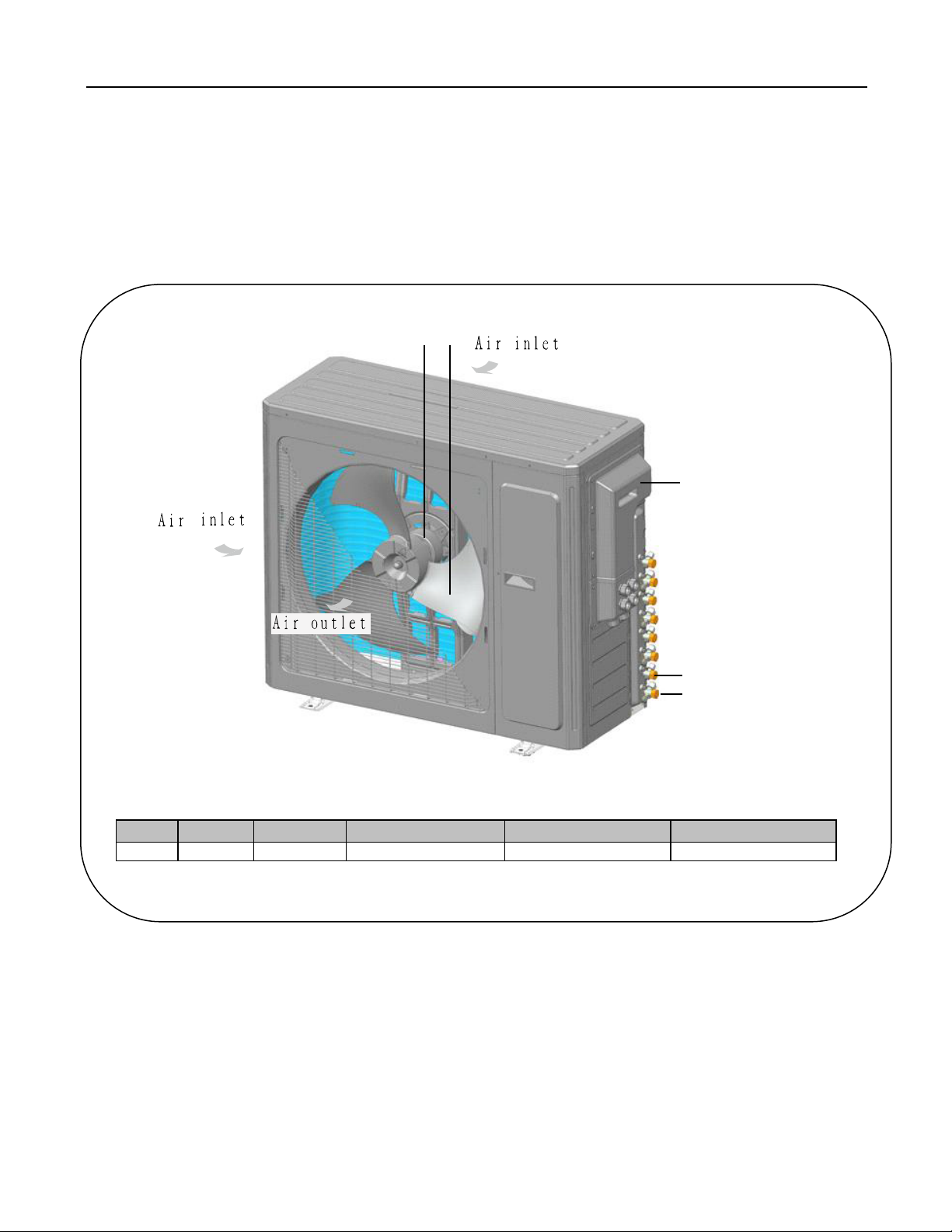
2.1 Name of Main Parts
①
②
③
④
⑤
MBRS42HPJ1OA*
NO.
①
②
③
④
⑤
Name
Motor
Fan
Electric Box
Gas valve assembly
Liquid valve assembly
Fig1
*MBRS36HPJ1OA SHOWN MBRS42HPJ1OA HAS 5 SETS OF ACCESS VALVES
Free match series
4
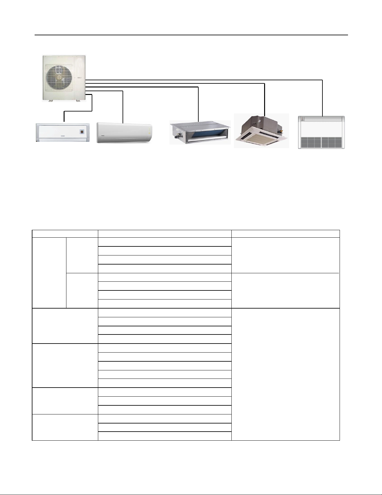
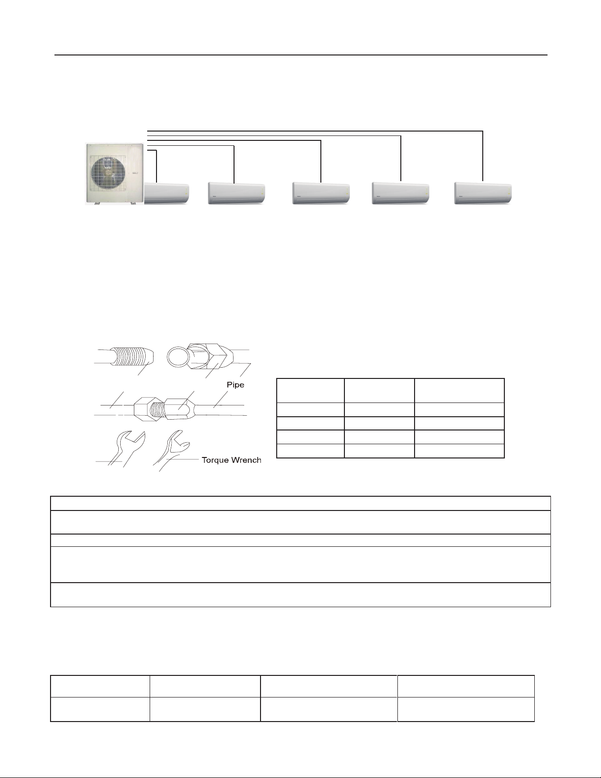
2.2 Combinations for outdoor and indoor units
Wall Mounted
Indoor Unit
Wall Mounted
Indoor Unit
Duct Type
Indoor Unit
Not Available
Cassettle Type
Indoor Unit
Not Available
Flooring Ceiling
Indoor Unit
Not Available
Fig 2
See Fig.2 for Combinations for Outdoor and Indoor Units. For the free match series air conditioning syst em, one
outdoor unit is able to drive up to five indoor units which can be cassette type, duct type, wall-mounted or floor
ceiling type. The outdoor unit will run as long as any one indoor unit receives the running command, and all indoor
units stop once the outdoor unit is turned off.
Table 1 Energy Level and Capacity Code of the Indoor
Indoor unit
Outdoor unit
Wall
mounted
Brisa MBRS42HPJ1OA
Flooring ceiling
Not Available
Duct type
Not Available
Cassettle type
Not Available
Console
Not Available
Capacity Code
09
12
18
24
09
12
18
24
09
12
18
24
09
12
18
21
24
12
18
24
09
12
18
Not Available
at this time

Free match series
5
2.3 Rated working condition
Table 2
Indoor side state
Outdoor side state
Dry buib temp.℉Wet buib temp.℉Dry buib temp.℉Wet buib temp.℉
Rating cooling
80.06
66.92
95
75.02
Rating Heating
69.98
60.08
47
43.00
NOTICE
1) The following listed cooling /heating capacity and noise is tested before outgoing.
2) The parameters below are tested under rated working condition. If there is any change to them, please refer to the
nameplate.
3) The parameters of heating capacity of indoor unit for heat pump excluded that of auxiliary electric heating power.
4) The performance parameters below are tested according to standard ANSI/AHRI 1230-2010.
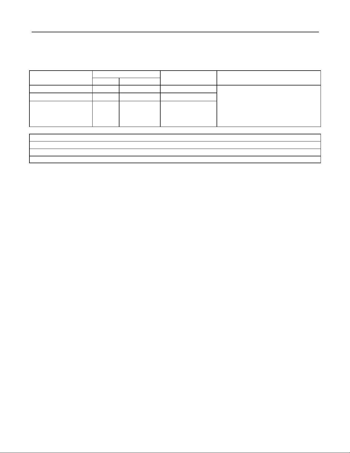
2.4 The range of production working temperature
Table 3
Cooling Working range Outdoor temperature 0~118℉
Heating Working range Outdoor temperature -4~86℉
Free match series
6
3 Preparation before Installation
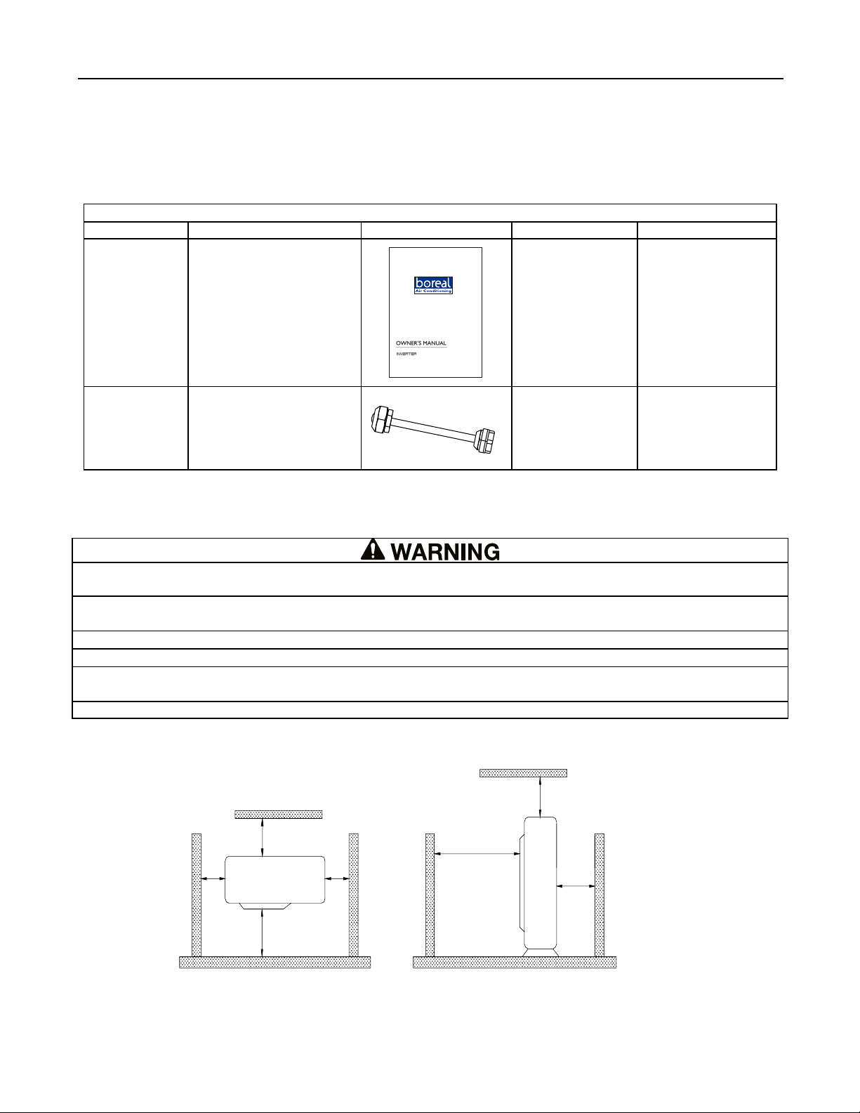
3.1 Standard parts
Please use the following standard parts supplied by us.
Table 4
Pars of Outdoor Unit
Number
name
picture
Quantity
Remark
1 Owner's manual 1
2 Tube connector
subassy
30K:8
36K:8
42K:9
3.2Selecting installation site
1) Install the unit at a place where is adequate to withstand the weight of the unit and make sure the unit would not
shake or fall off.
2) Never expose the unit under direct sunshine and rainfall. Install the unit at a place where is against dust,
typhoon and earthquake.
3) Try to keep the unit away from combustible, inflammable and corrosive gas or exhaust gas.
4) Leave some space for heat exchanging and servicing so as to guarantee unit normal operation.
5) Keep the indoor and outdoor units close to each other as much units close to each other as much the
pipe length and bends.
6) Never allow children to approach to the unit and take measures to prevent children touching the unit.
When the outdoor unit is totally surrounded by walls, the installation space of the unit should be as required in
Fig.3.
19 2/3
39 3/8
78 3/4
19 2/3
19 2/3
19 2/3
78 3/4
unit:inch
Fig 3
Split Air Conditioner
Thank you for choosing our product.
If you have lost the Owner’s Manual, please contact the local agent or visit
For proper operation, please read and keep this manual carefully.
Free match series
7
3.3 Piping Connection
The maximum pipe length is shown in the following table. When the distance between units (piping length) is
out of the range listed below, normal run of the unit can not be guaranteed.
Table 5
Model
Connecting Pipe (inch)
Max. Pipe length(ft) Max. Height Difference between Indoor
Unit and Outdoor Unit (ft)
Liquid
Gas
30K Ф1/4 Φ3/8 229.6
When the outdoor unit is above,
maximum height difference between
indoor and outdoor units is up to 49.2ft;
When the indoor unit is above,
maximum height difference between
indoor and outdoor units is up to 49.2ft;
36K Ф1/4 Ф3/8 246.1
MBRS42HPJ1OA Ф1/4 Ф3/8 246.1
NOTICE
1) Use water-proof insulating pipe.
2) Wall thickness of pipe: 0.019-0.039 inch; bearing pressure: 3.0MPa
3) The longer the connection pipe is, the more cooling and heating capacity will decrease.

Free match series
8
4 Installation Instruction
4.1 Outline and dimension of the outdoor
unit
MBRS42HPJ1OA
Outline dimension and Mounting holes
Fig 5
40
42 1/2
24 5/6
17 1/3
14 1/4
15 3/4
43 3/7
Unit:inch
Free match series
4.2 Installation of the Connection Pipe
Connecting piping for indoor unit and outdoor unit are in manifold mode. (As shown below).
Fig 6
4.2.1 Piping between the Indoor and Outdoor Units
(1) If the liquid and gas stop valves which have the sign of A , B, C, D or E have not been connected to the
indoor units, please turn off the screw cap with the spanner airproof.
(2) Refer to Fig.7 for the moments of torque for tightening screws.
(3) Let the flare end of the copper pipe point at the screw and then tighten the screw by hand.
(4) After that, tighten the screw by the torque wrench unit it clatters (as shown in Fig.7).
(5) The bending degree of the pipe can not be too small; otherwise it will crack. And please use a pipe tube
bender to bend the pipe.
(6) Wrap the exposed refrigerant pipe and the joints by sponge and then tighten them with the plastic tape.
P ip e F la r e N u t
S
p a n n e r
Fid 7
1) During the connection of the indoor unit and the refrigerant pipe, never pull any joints of the indoor unit by force;
otherwise the capillary pipe or other pipe may crack, which then would result in leakage.
2) The refrigerant pipe should be supported by brackets, that is, don’t let the unit withstand the weight of it.
3) If the piping connection size of outdoor unit does not match the piping connection size of indoor unit, use the
piping connection dimension of indoor unit. And use different-diameter joints which is installing on the place of
the piping connection to connect the indoor unit.
4) For the Free Match system, each pipe should be labeled to tell which system it belongs to avoid mistaken
inaccurate piping.
4.2.2 Allowable pipe length and drop height among indoor and outdoor units
If the total refrigerant pipe length (liquid pipe) is smaller than that listed in the table below, no additional
refrigerant will be charged.
Table 6
Model 30K 36K MBRS42HPJ1OA
Total Liquid Pipe
Lenght (a+b+c+d+e) 131.2ft 131.2ft 131.2ft
9
Pipe
diameter
Thickness of
copper tube
Tightening
torque
Φ1/4 inch
≥0.0315 inch
11
~
22 ft·lbf
Φ3/8 inch
≥0.0315 inch
26~29 ft·lbf
Φ1/2 inch
≥0.0315 inch
33~37 ft·lbf
Φ5/8 inch
≥0.0394 inch
44~48 ft·lbf

Free match series
10
Allowable Length and Height Fall of the Refrigerant Pipe
Table 7
b
a
e
d
c
L4L3L2 L5L1
tinuroodtuO
Height difference between indoor unit and outdoor unit H1
Height difference between
indoor units H2
Indoor unit
Indoor unit
Equivalent length of the farthest fitting pipe L
x
Fig 8
4.2.3 Installation of the Protection Layer of the Refrigerant Pipe
(1)The refrigerant pipe should be insulated by the insulating material and plastic tape in order to prevent
condensation and water leakage.
(2)The joints of the indoor unit should be wrapped with the insulating material and no gap is allowed on the joint
of the indoor unit, as shown in Fig.9.
Thermal insulating layer is required to be wrapped at this part.
Thermal insulating pipe
No gap
Fig 9
Allowable Value
MBRS42HPJ1OA
Fitting Pipe
Total length (actual length) of fitting
pipe 246.1ft L1+L2+…+LM(M ≤)5
Length of farthest fitting pipe (ft) 82ft LX(X=1,2,3,4,5)
Height difference
between outdoor
unit and indoor unit
Outdoor unit at
upper 49.2ft H1
Outdoor unit at
lower 49.2ft H3
Height difference between indoor
units (m) 24.6ft H2

Free match series
11
After the pipe is protected well enough, never bend it to form a small angle; otherwise it would crack or
break.
(3)Wrap the Pipe with Tape:
a. Bundle the refrigerant pipe and electric wire together with tape, and separate them from the drain pipe to
prevent the condensate water overflowing.
b. Wrap the pipe from the bottom of the outdoor unit to the top of the pipe where it enters the wall. During the
wrapping, the later circle should cover half of the former one.
c. Fix the wrapped pipe on the wall with clamps.
1) Do not wrap the pipe too tightly; otherwise the insulation effect would be weakened. Additionally, make sure the
drain hose is separated from the pipe.
2) After that, fill the hole on the wall with sealing material to prevent wind and rain coming into the room.
4.2.4 Support and protection for pipeline
Support should be made for hanging connection pipe. Distance between each support can not be over 1m.
4.3 Air Purging and Refrigerant Charge
4.3.1 Air purging
(1) The refrigerant has been charged into the outdoor unit before shipment, while additional refrigerant still need
be charged into the refrigerant pipe during the field installation.
(2) Check if the liquid valve and the gas valve of the outdoor unit are closed fully.
(3) As shown in the following figure (Fig.10), expel the gas inside the indoor unit and refrigerant pipe out by the
vacuum pump.
"LO"Knob "HI"Knob
Vacuuming pump
ManometerManometer
Connection hose
liquid valve
Gas valve
Fig 10
(4) When the compressor is not running, charge the R410A refrigerant into the refrigerant pipe from the liquid
valve of the outdoor unit (do not do it from the gas valve).
4.3.2 Additional refrigerant charging
(1) Refrigerant Charge in the Outdoor Unit before Shipment
NOTICE
1) Outdoor unit has been charged refrigerant before delivery. The refrigerant charge is not included those charged
additionally in the indoor unit and the refrigerant pipe.
2) The amount of the additional refrigerant charge is dependent on the diameter and length of the liquid refrigerant
pipe which is decided by the actual yield installation requirement.
3) Record the additional refrigerant charge for future maintenance.
Free match series
12
(2) Calculation of the Additional Refrigerant Charge
Additional Refrigerant Charge=
(ΣLength of Liquid Pipe φ0.375×54+ ΣLength of Liquid Pipe φ0.25×22)-880
The biggest additional refrigerant charge value is 800g. It means that if the calculated value exceed 800g, the
additional refrigerant charge takes 800g, while the calculated value less than 800g, the additional refrigerant charge
takes the calculated value.
4.4 Electric Wiring
4.4.1 Wiring precautions
(1) The installation must be done in accordance with the national wiring regulations.
(2) Only the power cord with the rated voltage and exclusive circuit for the air conditioning can be used.
(3) Do not pull the power cord by force.
(4) The electric installation should be carried out by the technician as instructed by the local laws, regulations
and also this manual.
(5) The diameter of the power cord should be large enough and once it is damaged it must be replaced by the
dedicated one.
(6) The earthing should be reliable and the earth wire should be connected to the dedicated device of the building
by the technician. Besides, the circuit breaker coupled with the leakage current protection switch must be equipped,
which is of enough capacity and of both magnetic and thermal tripping functions in case of the short circuit and
overload. Table 8
30K
Fig 11
Models Power Supply Capacity of circuit breaker(A)Recommended Cord(pieces×
sectional area)
30K 208/230V~60Hz 30 3× 0.0062 sq in
36K 208/230V~60Hz 35 3× 0.0062 sq in
MBRS42HPJ1OA 208/230V~60Hz 40 3× 0.0062 sq in

Free match series
13
MBRS42HPJ1OA
Fig 12
4.4.2 Earthing Requirements
(1) The air conditioner is classified into the Class I appliances, so its earthing must be reliable.
(2) The yellow-green line of the air conditioner is the earth line and can not be used for other purpose, cut off or
fixed by the tapping screw; otherwise it would cause the hazard of electric shock.
(3) The reliable earth terminal should be provided and the earth wire can not be connected to any of the following
places.
①Running water pipe;;②Coal gas pipe; ③Sewage pipe; ④Other places where the professional personnel
think unreliable.
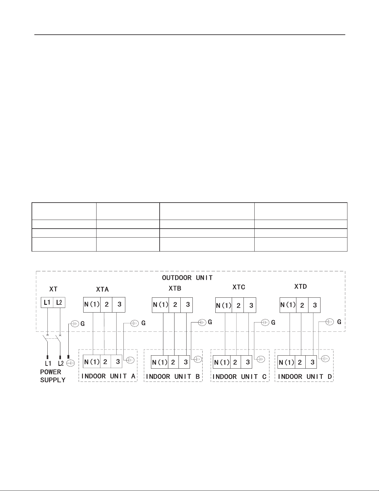
4.4.3 Electrical Cable Connection
1) The mistake connecting line will result in malfunction. After the electrical wiring working, ensure the wire
between the connection place and the fixed place has a certain freedom degree.
2) The connection piping and connection line of each indoor unit should connect well according to the instruction.
3) The electric installation should be carried out by the technician as instructed by the local laws, regulations and
also this manual.
4) The installation location should be dry, and can't be expose in direct sunlight or strong breeze.
5) Have to install a breaker in the circuit that can shut off the main power supply of the system. Besides, the air
switch coupled with the leakage current protection switch must be equipped.
4.4.4 Wiring of the Power Cord
If the supply cord is damaged, it must be replaced by the manufacturer
or its service agent or a similarly qualified person in order to avoid a hazard.
(1). Open the side plate.
(2). Connect the power cord to the terminals “L1”, “L2”and also the earthing screw, and then connect the wiring
terminals “N(1),2,3”of the indoor unit to those of the outdoor unit correspondingly. Please use the green bonding screw
to connect the earthing cord. The location is showing in the figure 13.
(3). Fix the power cord with wire clips.
(4). Let the power cord go through the rubber ring.
Tighten the green
bonding screw here
Figure 13

Free match series
14
5 Troubleshooting
1) In the event of abnormal conditions (like, stinky smell), please shut off the main power supply immediately and
then contact the appointed service center; otherwise the continuous abnormal running would damage the
air conditioning unit and also would cause electric shock or fire hazard etc.
2) Do not repair the air conditioning personally but instead contact the professionally skilled personnel at the
appointed service center, as the incorrect repair would cause electric shock or fire hazard etc.
Check before Contacting Service Center.
Table 9
Check Items
Conditions Might Happen
Check
Has the unit been fixed firmly?
The unit may drop, shake or emit noise.
Have you done the gas leakage test?
It may cause insufficient cooling/heating
capacity.
Is the unit get proper thermal insulation?
It may cause condensation and dripping.
Does the unit drain well?
It may cause condensation and dripping.
Is the voltage in accordance with the
rated voltage specified on the nameplate?
It may cause malfunction or damage the part.
Is the electric wiring and piping
connection installed correctly and
securely?
It may cause malfunction or damage the part.
Has the unit been earthed securely?
It may cause electrical leakage.
Is the power cord specified?
It may cause malfunction or damage the part.
Has the inlet and outlet been blocked?
It may cause insufficient cooling/heating
capacity.
NOTICE!
If the air conditioner still runs abnormally after the above check and handling, please contact the
maintenance serviceman at the local appointed service center and also give a description of the error occurred
as well as the model of the unit.
Free match series
15
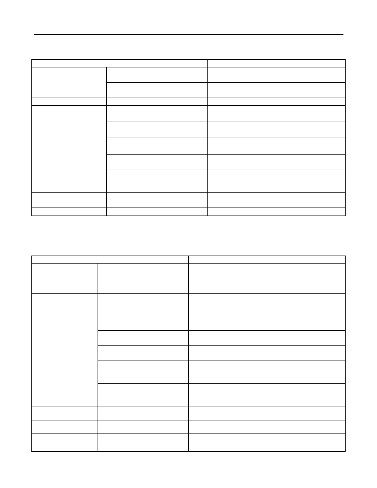
6 The conditions listed below are not classified into errors.
Table 10
Conditions
Causes
The unit does not run
When restart the unit soon after it is
stopped.
The overload protection switch of the unit let the
startup delayed for three minutes.
As soon as power is on.
The unit will stand by for approximate one
minute.
The unit blows out mist
When the cooling operation starts.
The hi-humidity air indoor is cooled quickly.
The unit generates noise
The unit “ clatters” as soon as it
starts running.
It is the sound generated during the initialization
of the electronic expansion valve.
The unit “ swishes ” during the
cooling operation.
It is the sound when the refrigerant gas runs inside
the unit.
The unit “ swishes ” when it is
started or stopped.
It is the sound when the refrigerant gas stops
running.
The unit “ swishes” when it is in
and after the running.
It is the sound when the draining system is
operating.
The unit “ squeaks” when it is in
and after the running.
It is the sound of frication generated by the skin
plate etc which swells due to the temperature
change.
The unit blows out dust.
When the unit restarts after it is not
used for a long time.
The dust inside the unit is blown out again.
The unit emits odors.
When the unit is running.
The odors absorbed in are blown out again.
NOTICE!
If problem can not be solved after checking the above items, please contact service center and show
phenomena and models.
Following circumstance are not malfunction
Table 11
Malfunction
Reason
Unit doesn’t run
When unit is started
immediately after it is just
turned off
Overload protection switch makes it run after 3 minutes
delay
When power is turned on
Standby operating for about 1 minute
Mist comes from the
unit
Under cooling
Indoor high humidity air is cooled rapidly
Noise is emitted
Slight cracking sound is heard
when just turned on
It is noise when electronic expansion valve initialization
There is consecutive sound
when cooling
That's sound for gas refrigerant flowing in unit
There is sound when unit starts
or stops
That's sound for gas refrigerant stops to flow
There is slight and consecutive
sound when unit is running or
after running
That's sound for operation of drainage system
Cracking sound is heard when
unit is operating and after
operating
That’s sound caused by expansion of panel and other
parts due to temperature change
The unit blows out
duct
When unit runs after no
operation for a long period
Dust in indoor unit is blew out
The unit emits odor
Operating
The room odor absorbed by the unit is blew out again
Indoor unit still runs
after switch off
After every indoor unit receive
"stop" signal, fan will keep
Indoor fan motor will keep running 20-70s so as to take
good use of excess cooling and heating and prepare for

Free match series
16
running
next operation
Mode conflict
COOL or HEAT mode can not
be operated
When the indoor operating mode conflicts with that of
outdoor unit, indoor fault indicator will flash and conflict
will be shown on the wired controller after 5 minutes.
Indoor unit stops to run and meanwhile change outdoor
operating mode as the same as that of indoor unit, then
the unit will go back to normal. COOL mode doesn't
conflict with DRY mode. FAN mode doesn't conflict with
any mode.
Table of contents
Other Boreal Air Conditioner manuals


Popular Air Conditioner manuals by other brands


Fujitsu
Fujitsu General ASHH30KMTB Service manual

Airwell
Airwell Dakota DCI Series Service manual

Panasonic
Panasonic CS-E9CKP operating instructions

Panasonic
Panasonic CS-CZ25WKE Service manual

Challenge
Challenge MPPHA-05CRN1-QB6 instruction manual

Mitsubishi Electric
Mitsubishi Electric MSZ-DM25VA operating instructions

EcoNet
EcoNet A2024AJVCA installation instructions

Airwell
Airwell Electra JMF Hi wall Series Service manual

Hitachi
Hitachi RAS-E10HB instruction manual

GE
GE AHE18 Series Owner's manual and installation instructions

Mitsubishi Electric
Mitsubishi Electric MSC-GE20VB operating instructions

Mitsubishi Electric
Mitsubishi Electric NTXFKs15a112a Series manual