BOREY TECH T Series User manual

BEI JING BOREYTECH CO., LTD Website:www.en.boreytech.com
BOREY-T Series of instructions
This manual applies to the following
models:
BOREY T15-F24-T2
BOREY T15-F30-T4/L4/T4C
BOREY T15-F40-T4
BOREY T15-L600-L2
BOREY T15-L1200-L2

BEI JING BOREYTECH CO., LTD Website:www.en.boreytech.com
Content
Prepare
ⅠPr od uct str u ctur e
1 structure instruction
2 Button instruction
3 Operation menu
ⅡF eed er i n sta l l
1 Installation prepare
2 Install
ⅢU ser
1 Power supply
2 Basic Parameters Set
2.1Set component’s coordinate
2.2Set nozzle’s height
2.3Set speed
2.4Set suction deply
2.5Set mounting height
2.6Set mounting speed
2.7Set mounting deply
2.8Copy feeder’s parameters
2.9Set X and Y speed

BEI JING BOREYTECH CO., LTD Website:www.en.boreytech.com
2.10Three-point correction
2.11Set vision camera
2.12Set vision brightness
ⅣSoftware
1 Open software
2 Software menu
3 Position nozzle’s coordinate
4 Software set
4.1vision range
4.2image limit value
4.3pixel ratio
4.4image delay
4.5communication
4.6save parameters
ⅤProgram
1 irregular board
2 jointed board
2.1program smallest board
2.2Set first array’s amount
2.3Set first array’s basic point
2.4Set second array’s amount
2.5Set second array’s basic point
BEI JING BOREYTECH CO., LTD Website:www.en.boreytech.com
ⅥMount
Warranty
Warning:Please read the manual before using the equipment forsafety operation
Statement:
•This manual and the specifications are subject to change without notice.For
more changes please visit our company’s official website or contact us.
Warning:
•Please operate the machine with right safty process,or it may be damaged,there
will be a risk of injury to the operator,this device should be moved under the
condition of power failure.
•Please operate this equipment with proper protection and installing place
•One worker one machine has been suggested;Operatorshould give tip that
“Leave dangerous position”.
•In the operation of this machine,it is strictly prohibited two operations at the
same time,or there will be ijuries.
•Before the repair and maintenance,please cut off the power,otherwise operating
personnel were in zccident.
Prepare
Air compressor is necessary for negative pressure generator and feeder system on the
machine,so please prepare air compressor and set 0.5Mpa,running 0.65Mpa stop;And
output connector should be connected with outer diameter 10MM air pipe.
The storage capacity of air compressor should be more than 40L,and power supply is
AC220V,independent output is 10A in power outlet;Please don’t use other machines which
need more power consumption.

BEI JING BOREYTECH CO., LTD Website:www.en.boreytech.com
ⅠProduct description
1.Structure
1.Mounting head assembly
2.Feeder(automatic feeder)
3.X axis motor
4.Y axis motor
5.P axis sliding table
6.Feeder fixed board
7.X axis wire drag chain
8.Y axis wire drag chain
1.Mounting assembly 1
2.Mounting assembly 2
3.Vacuum generator 1
4.Vacuum generator 2
5.Z axis drive crank arm
6.Z axis sensor
7.X axis sensor

BEI JING BOREYTECH CO., LTD Website:www.en.boreytech.com
1.Angle rotating machine
2.Synchronous transmission system
3.Nozzle lock copper bush
4.Nozzle

BEI JING BOREYTECH CO., LTD Website:www.en.boreytech.com
2.The operation buttons introduction
1)Factory mode
2)Moving speed option key of each axis(long span,the coarse tuning and fine tuning)
3)Nozzle change
4)Shelf frame +
5)Shelf frame -
6)Page up
7)Page down
8)Shelf frame coordinate quickly positioned and saved in the basic parameter settings.
9)Open feeder cover in the basic parameter settings.
Next component in programming operation.
10)Sending one component to corresponding feeder in the basic parameter settings.
Quickly position to current component coordinate in programming operation.
11)Test and pick current shelf frame component in the basic parameter settings.
Valid change of component in programming operation.
12)Save and confirm key.
13)Cancel and confirm key.
14)Y axis moves to ↑
15)X or P axis(sliding table) moves to ←
16)Y axis moves to ↓
17)X or P axis(sliding table) moves to →
18)Selected nozzle risen.
19)Selected nozzle rotated counted clockwise.
20)Selected nozzle down.
21)Selected nozzle rotated clockwise.

BEI JING BOREYTECH CO., LTD Website:www.en.boreytech.com
3.Operating Menu
Basic parameters set
1.X.Y.P axis coordinate
2.Current nozzle number and turn angle(TURN)and Down deep height(HIGH)
3.Current X.Y.P moving speed
4.Current removable platform
5.Current shelf frame number
6.Current parameter page and function specification
Programming operating interface
1.Current component number
2.Saved component number
3.Whether current component is mounted,effective for mounted ,invalid for not mounted
ⅡInstall Feeder
Pneumatic feeders are installed on the machine,please select suitable feeders
such as:8mm,12mm,16mm,etc..Please prepare an anti-static tweezer before

BEI JING BOREYTECH CO., LTD Website:www.en.boreytech.com
installing feeders.
1 Install steps:
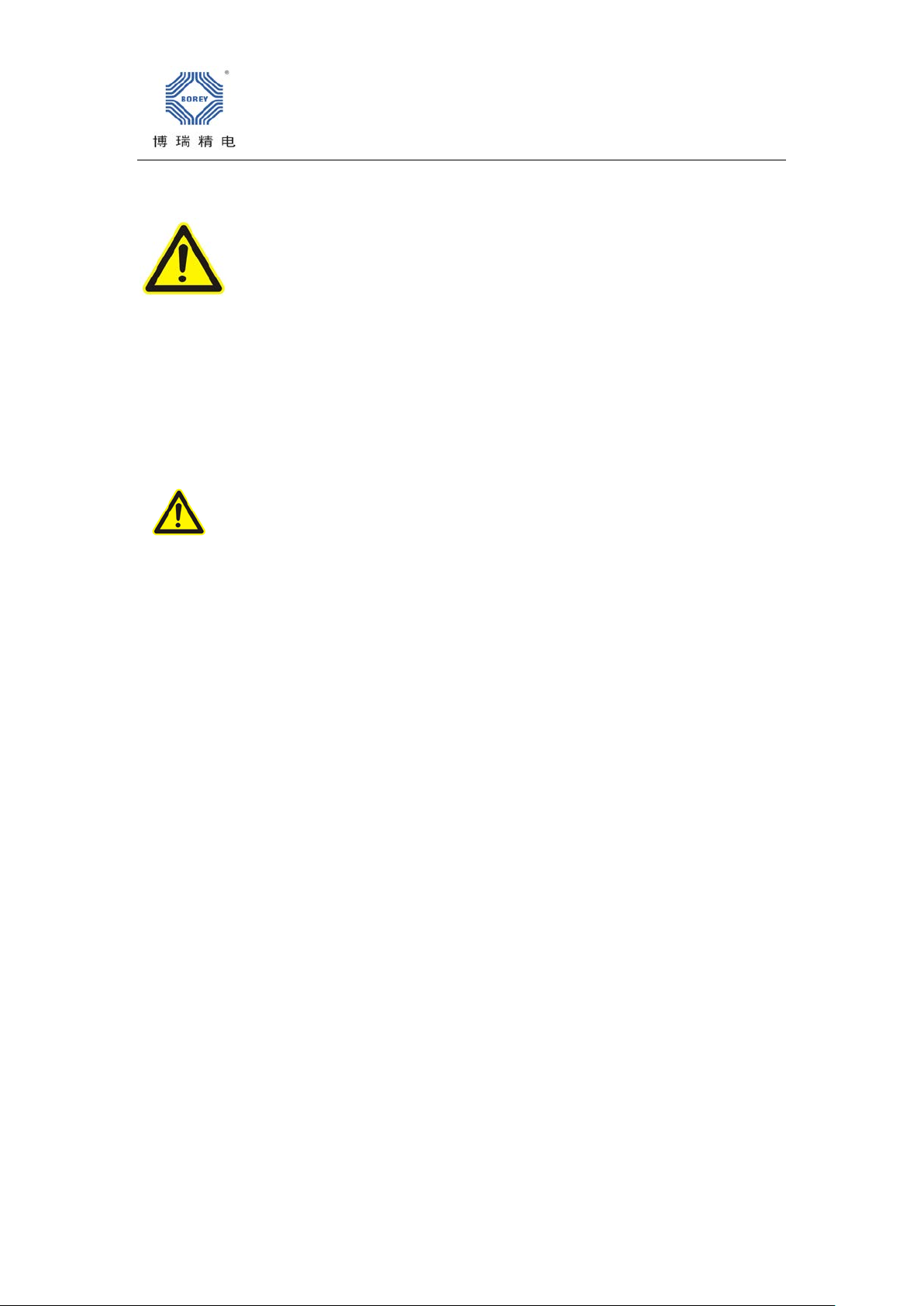
1.Open the feeder to loading state
Lift feeder fixed handle,left hand press feeder handle,while the right hand hold the small
metal piece on the right side of the feeder ,and then release the feeder handle ,loosen the
small metal piece on the right hand after there is effective tilt(Figure 1)
Figure 1
2.Installing the tray
Place the trays in tray warehouse behind the feeder.Pull out about 10cm long strip to
separate the epidermis and the strip,as shown in Figure 1 into the transfer positions.Part of
the strip should be close to the gear ,the material skin needs to cross the upper slotting
(Figure 2)into the middle of the two gears after through two white guide wheels.
BEI JING BOREYTECH CO., LTD Website:www.en.boreytech.com
Figure 2
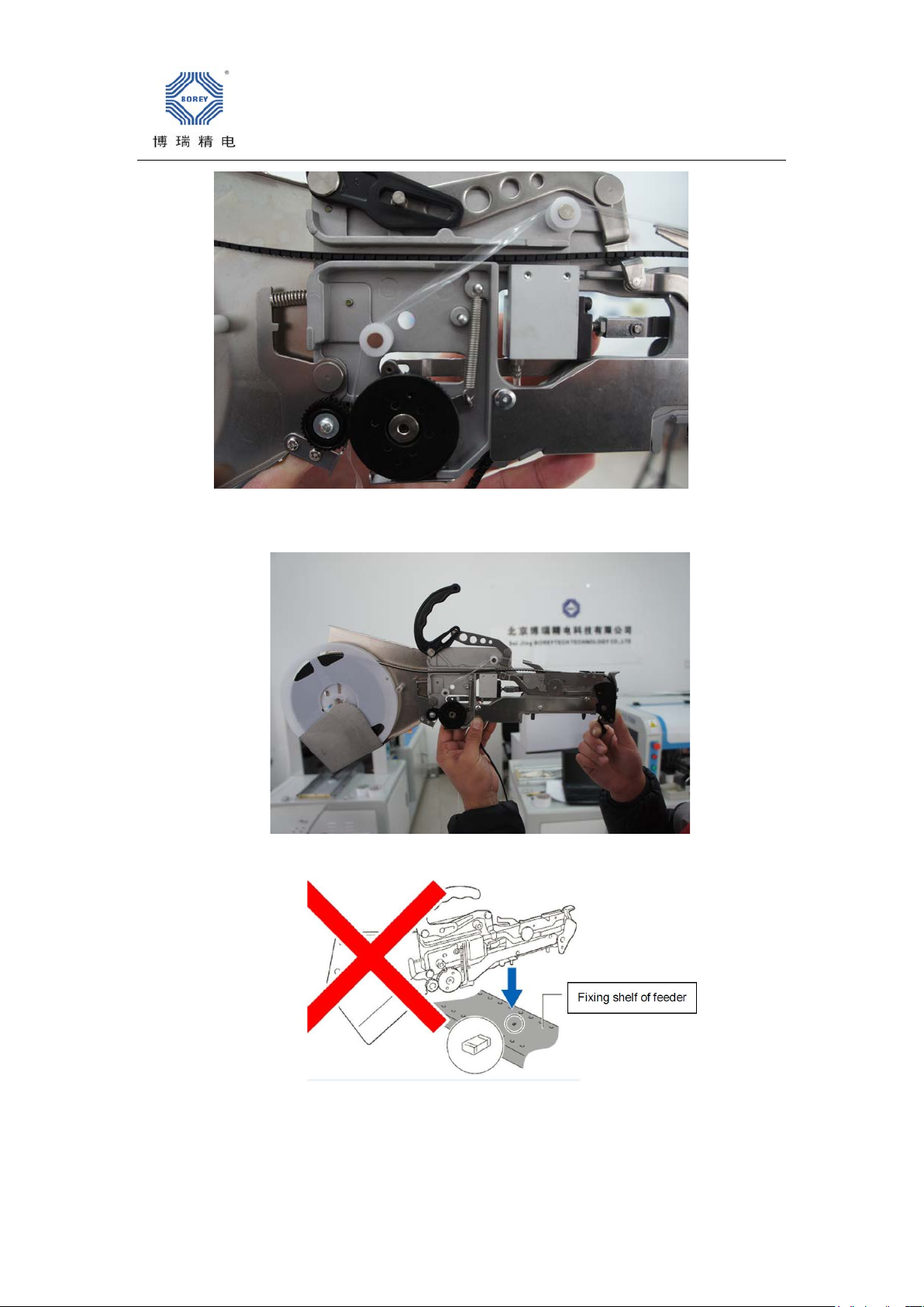
Figure 3 is after installing finished.
Figure 3
Notice:when installing feeder,if feeling its handle has no pressed or it is not correct
position,please don’t install machine,or that will result feeder fallin during running.
BEI JING BOREYTECH CO., LTD Website:www.en.boreytech.com
Notice:Please keep no object on feeder’s fixing board,and making feeder’s surface is
close with fixing board,and handle is important to lock feeder,please protect it.
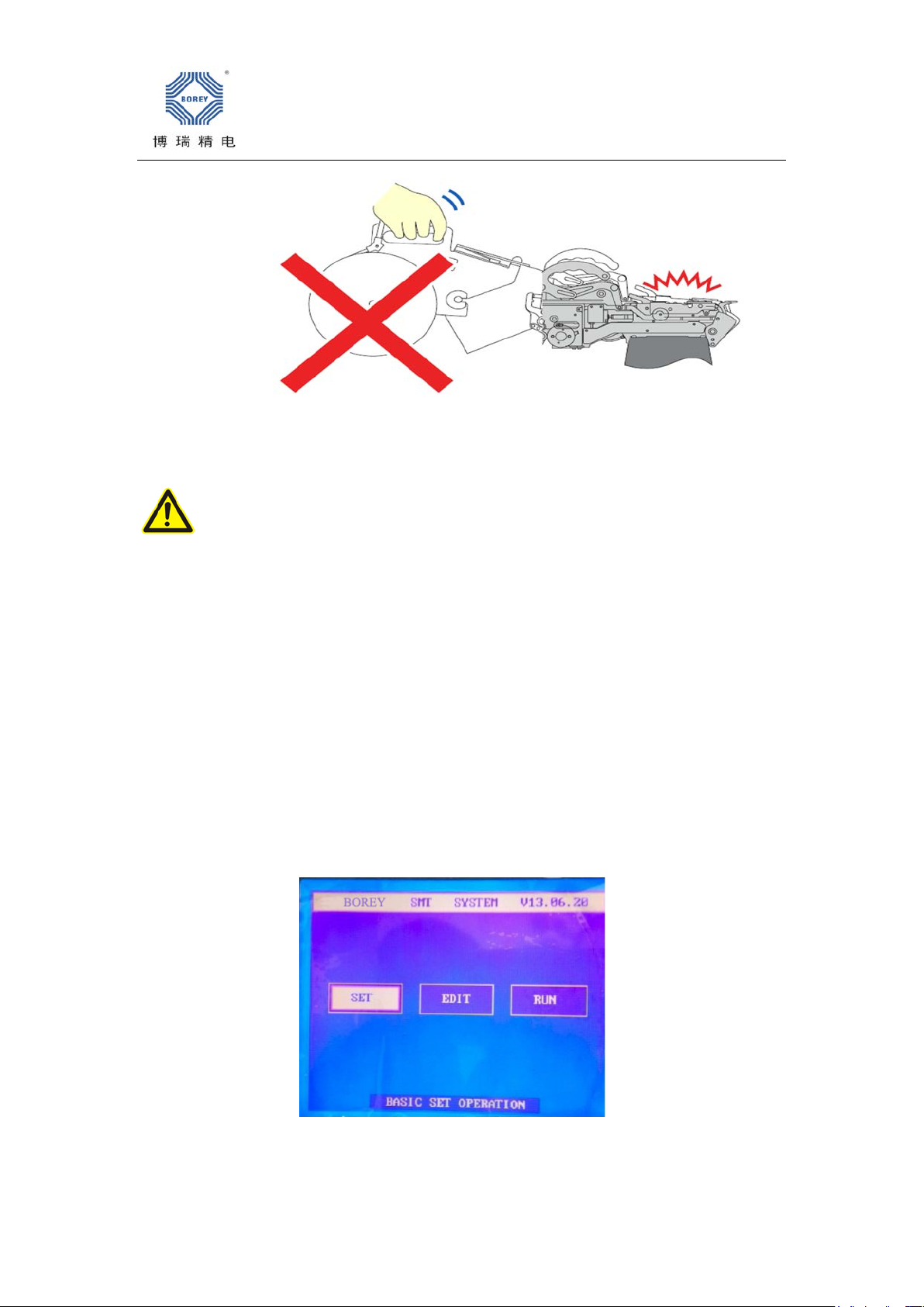
Please don’t move feeders during machine is running,it is very dangerous.
ⅢUse
1 Turn on power supply
Connect power and machine,close air switch at the back of the machine,release urgent stop
button(there are two URGENT stop buttons,both are released),red power light is on,then
rotate RUN button with clockwise 90°,green RUN light will be on and the screen appears
our LOGO,at this point all setting is 0 position
2.Basic parameters set
As the picture:
2.1.Set the coordinate of the suction component
As the picture:

BEI JING BOREYTECH CO., LTD Website:www.en.boreytech.com
Firstly select feeder stack’s No.,press F1 to finish fast position up to the top of the
corresponding stack,press F2 to open the feeder cover,switching to coarse adjustment and
move XY axis to make cross mark of camera is in the center of component,then press OK to
save.Set other coordinates separately.See above picture.
2.2Setting the height of feeder
As the picture:
Press F2 to open the feeder cover,move Corresponding nozzle on the top of componen
“z&a:keep pressing up and down key”and hold↓,when touching components,the height is
suction height,then press OK to save.Two nozzles should be set separately.
Notice!!Do not press angle motor of nozzles by hands;If do that will result damage motors or
nozzles can;t return.
2.3.Set suction speed
As the picture

BEI JING BOREYTECH CO., LTD Website:www.en.boreytech.com
Press Nozzle rotating button to adjust speed(1--9), stable speed is about 6-8;after
adjusting,please Ok to save;Please set two nozzles separately.See picture
2.4Set suction delay
As the picture:
According to the mounting effect by using the rotation key of the nozzle to adjust the delay
level
(1~9),(steady speed level is about 1~2),after adjustment ,press OK to save.The two
nozzles should be set separately.
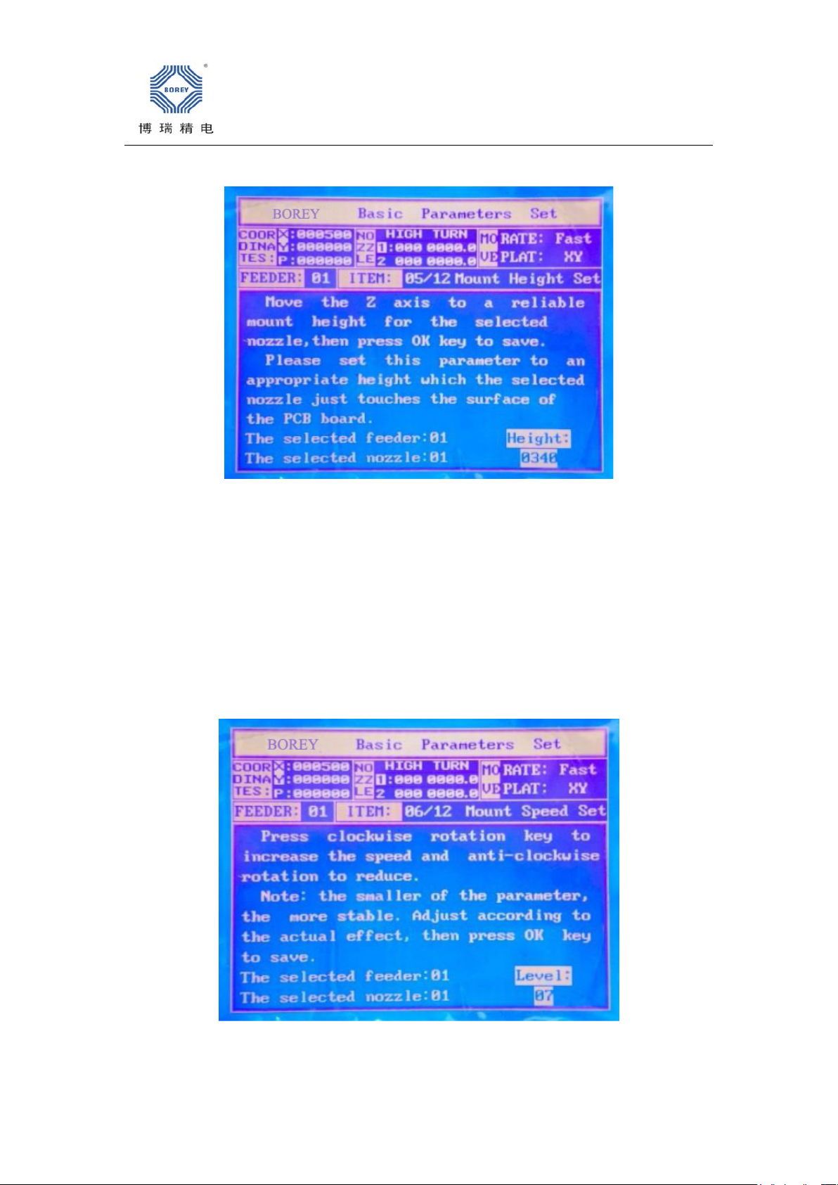
2.5Set mounting height of Nozzles
BEI JING BOREYTECH CO., LTD Website:www.en.boreytech.com
As the picture:
Press the Factory +Speed combination key to swith the coordinate from XY to the sliding
table,and then press→←to move the sliding table to below the nozzle ,then press↑↓to adjust
mount height,for resistance and thin components,generally when contact with sliding
table,for thick materials may be compensate for the height difference appropriately,and then
press OK to save.The two nozzles should be set separately.
2.6Nozzle mounting speed setting
As the picture:
According to the mounting effect by using the rotation key of the nozzle to adjust the nozzle
mounting speed level(1~9).Steady speed is about 6~8.The two nozzle should be set
BEI JING BOREYTECH CO., LTD Website:www.en.boreytech.com
separately.
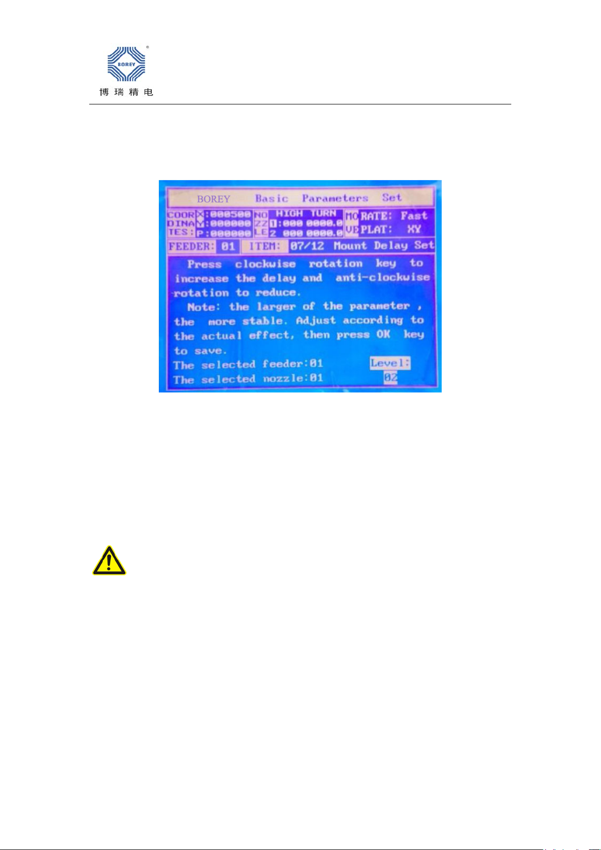
2.7Nozzle mounting setting
As the picture:
According to the mounting effect by using the rotation key of the nozzle to adjust the delay
level(1~9),(steady speed level is about1~2),after adjustment,press OK to save.The two
nozzles should be set separately.
2.8.Shelf parameters copy
Attention:If all the materials of the shelf are the same,you can use item to copy
replication calibrated shelf to all shelves,the suction height,suction speed,suction
delay,mounting height,mounting speed and mounting delay of all shelves are consistent with
the target shelf!
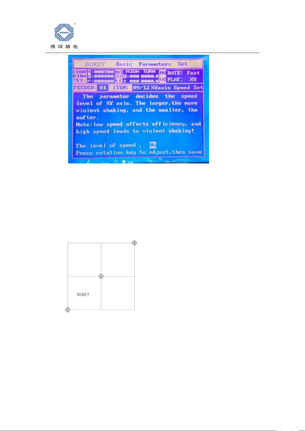
2.9.X Y axis speed setting
As the picture:
BEI JING BOREYTECH CO., LTD Website:www.en.boreytech.com
Use the rotation key of the nozzle to adjust,the speed level(1~9),steady speed is7~9,if
feeling the machine shaking violently,please reduce the speed rate.The difference between 8
and 9 level is not large,but sharking less at 8 level.
2.10.Three-point calibration
A coordinate disc (shown as Figure 1)
Suppose the uppermost point is reference point No.1,the middle point is reference point
No.2,the lowermost point is reference point No.3,F2 to swith para-component,F3 to switch
the reference point.
Setup steps:

BEI JING BOREYTECH CO., LTD Website:www.en.boreytech.com
1.Press F2 to switch to the camera,and the press F3 to switch to the reference point No.1.
2.Move the XY axis to make the camera crosshairs aligned with the center of reference
Point 1,and press OK to save.
3.Then press F2 to swith to Nozzle 1,and then move the XY axis to make Nozzle 1 aligned
with the center of the reference Point 1.Press OK to save.
4.Then press F2 to switch to Nozzle 2,and then move the XY axis to make Nozzle 2 aligned
with the center of the reference Point 1. Press OK to save.At this point,saving the 1st
reference point is completed.
In order to accurately set the three reference points,the setting method of the other two
reference points and reference Point 1 is the same.
The more accurate the setting parameter is,the more precise is the coordinate camera
instructing and the coordinate actual nozzle reaching.Recommend that do a three-point
correction when replacing the nozzle,the mounting effect will be greatly improved!
At this point,the basic parameter settings have been completed.But need to pay attention:the
coordinates of the suction,suction height,mounting height,three-point correction are the
settings must be dong for normal operation of the machine.The other speed settings can keep
the default parameters.
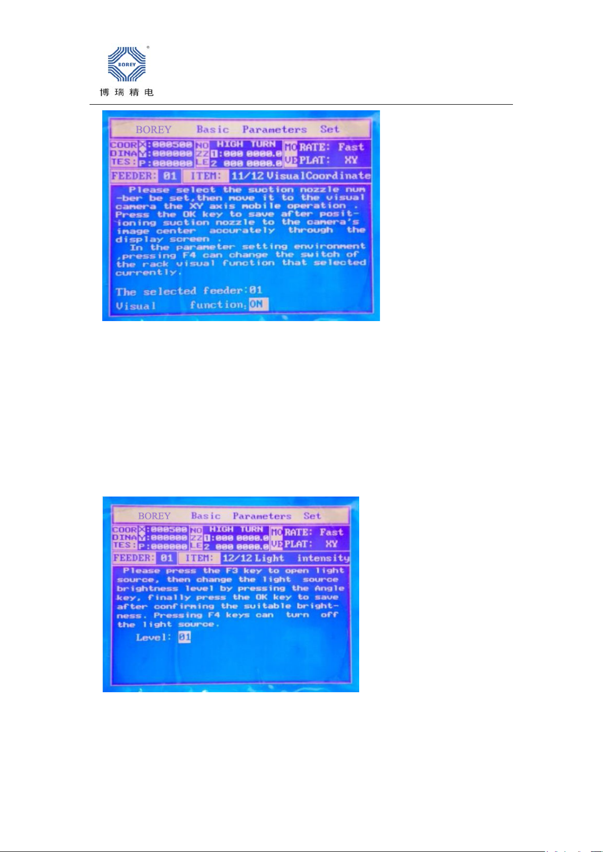
2.11. Vision camera coordinate
BEI JING BOREYTECH CO., LTD Website:www.en.boreytech.com
This fuction is used to select which feeder stack need run vision recognition;The fuction can
be set independently in every feeder stack;For low accurate components,turn off the fuction
can improve working efficiency.Step is blow:Press feeder +- to select feeder number,then
press F4 to swith ON/OFF.
Notice:when nozzle’s position is same with camera’s position,please set nozzle’s center point
align with camera’s cross.Please set Nozzle 1 and 2 independently,then OK to save.
2.12Set vision brightness
This function is used to set upward camera’s brightness;F3 is turn on,F4 is turn off.This
fuction is used with PC together.

BEI JING BOREYTECH CO., LTD Website:www.en.boreytech.com
ⅢSoftware
1Running software
2Software menu
Turn on camera:turn on vision input;please click it to turn on camera after running
software;
Turn off camera:turn off vision input;
Turn on/off communication:Turn on or off communication between PC and machine;
Vertical camera:it is in the bottom of pick and place head,taking photos from up to
down,mainly used in program and setting coordinate of feeders.
Upward camera:it is on the fixing board,taking photos from down to up,mainly used to
correct vision.
Vision range:Seeting image’s scanning sizes,it is proportional with sizes of components and
nozzles.
Image limit value:it is used to recognize limit value of components and background in
image,usually set 127.
Pixel ratio:it is proportion relation between image pixel and XY step distance.
Image delay:it is photo delay from camera taking components to get image.
Communication connector:it is used to set PC communication.
Parameters setting:it is used to save parameters;Please click it to save changed data.
Vision result:it is used to show vision data and accuracy.
Vision data:Calculated data after vision recognition.
Recognition test:When click this button,upward camera will be turned on and take one
photo,then do vision recognition,they can be used for parameters setting.
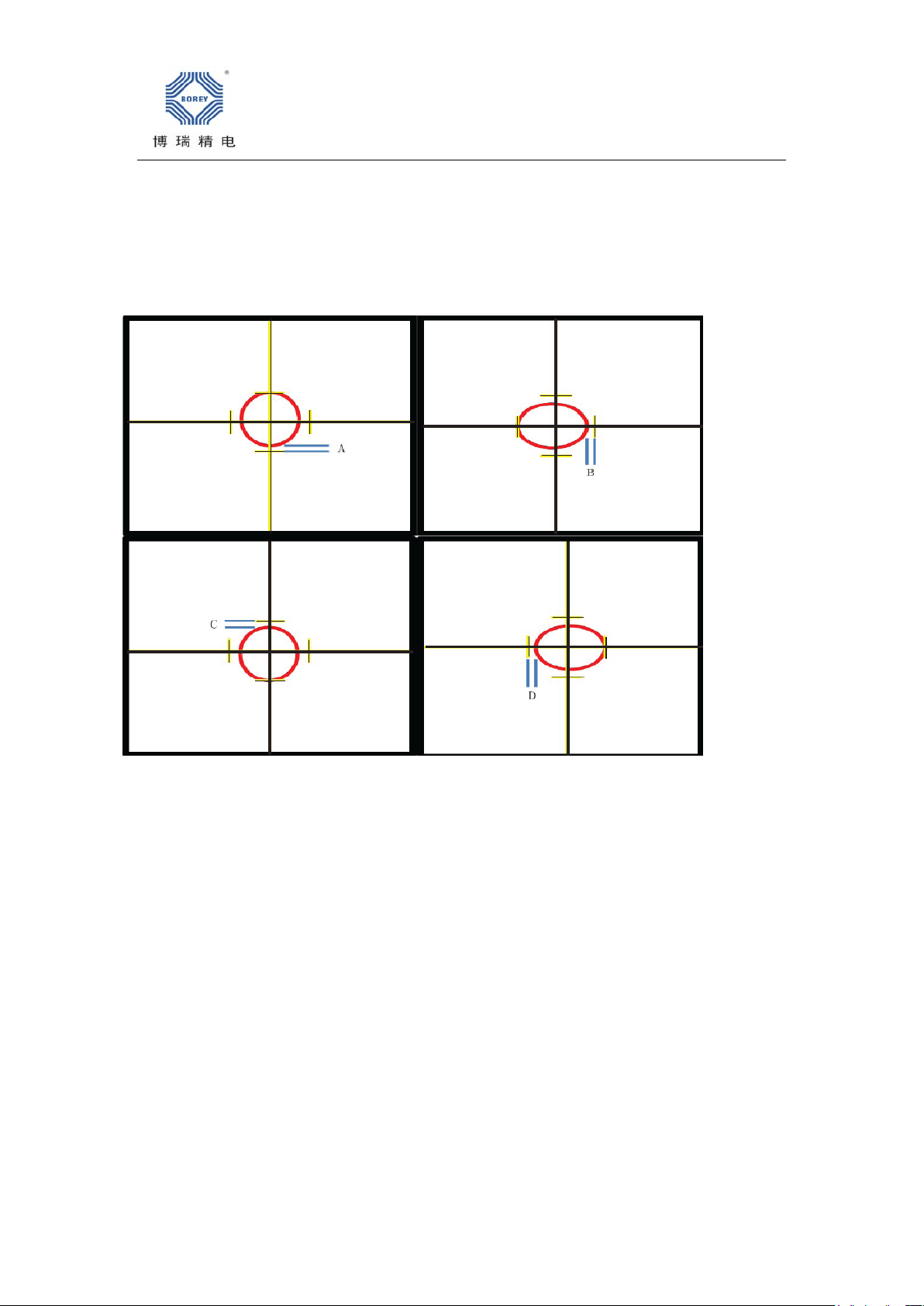
3Nozzle vision coordinate
Imortant:Nozzle’center should be aligned with camera’s center.
BEI JING BOREYTECH CO., LTD Website:www.en.boreytech.com
Operation:
Please open software,then turn camera and swith to upward camera,moving nozzle to cross
center of camera,try to find point like below(We set ellipse center point is signalized
point,and linner diameter of nozzle is ellipse,in fact there is no much deviation in nozzles).
Adjust X Yand Nozzle’s roating to making space of A(0°)、B(-90°)、C(-180°)、D(-270°)are
same,then save it in item 11 which is nozzle’s coordinate.(Image taken by camera is magnified
more times)
4Software
Brightness adjust
Please pick one component by nozzle,then move it to camera’s center,adjust brightness to
ensure much different between component and background(Please see Basic Parameters Set
item 11,select relate nozzle and then F1 fast position);usually component is white,background is
dark red;brightness is too strong or weak will result error.Please see below picture:
This manual suits for next models
7
Popular Industrial Equipment manuals by other brands


Siemens
Siemens SENTRON VL1250 operating instructions

Command access
Command access MLRK1 Series Insert Instructions

Mecc Alte spa
Mecc Alte spa TR1 Series Use and maintenance manual

Ralco
Ralco R605DASM instruction manual

Multitel
Multitel MX 250 USE AND WARNING INSTRUCTIONS

Carel
Carel uboss Assembly procedure