5K
12(ac)
10(ac)
14(ac)
18(ac)
12(ac)
10(ac)
28(ac)
30(ac)
u
(i)
u
2/12 Bosch Rexroth AG Hydraulics VT-VSPA1-1 and VT-VSPA1K-1 RE 30111/09.05
Orderin code
Amplifiers for controlled proportional pressure
control valves, analogue, with one solenoid
With 32-pin male connector and front panel = No code
With 16-pin terminal strip; without front panel = K
Further details in clear text
1X = Component series 10 to 19
(10 to 19: unchanged technical data and pin
assignment)
VT-VSPA1 1 1X *
For substitutes for amplifier types VT 2000 (up to
component series 4X), VT 2010, VT 2013 or VT 2023
for rac installation, blind plate 4TE/3HE must be or-
dered separately. Material no. R900021004
Functional description
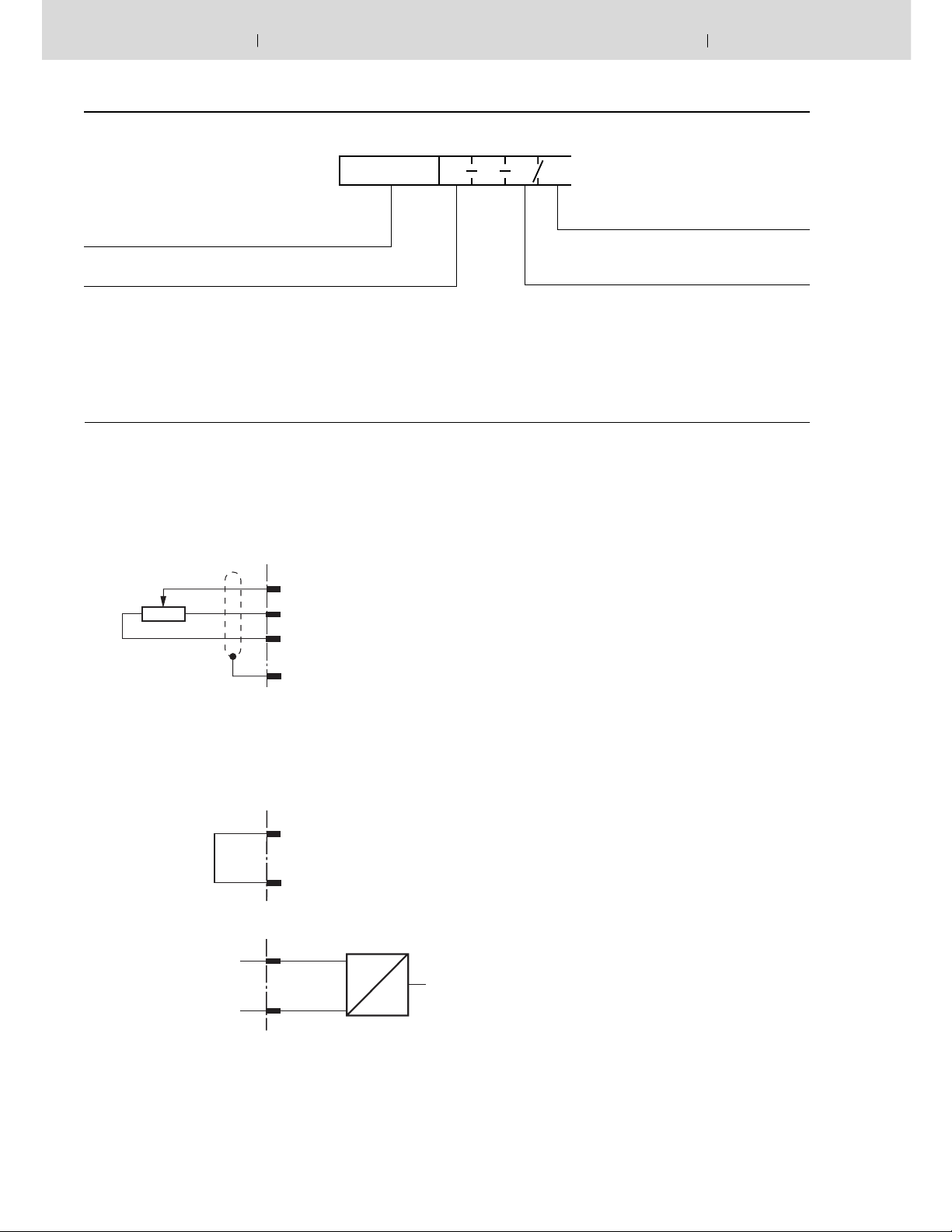
The command value voltage is applied to command value input
1 either directly or via an external command value potentiometer
with
the help of the regulated + 9V voltage from the power supply
unit [14].
The following is valid for this input: +9 V +100 % 1).
External command value feedforward
Input 1
+9 V
M0
Note:
When an external command value potentiometer is used, in-
ter nal potentiometer "Gw" [3] must be set to maximum or the
required maximum pressure.
Input 1
+9 V
Differential input (input 2)
0 to +10 V / 4 to 20 mA
0 to 20 mA
0V reference potential
Additions to the pin desi nati-
ons in brackets are only valid
for type VT-VSPA1-1.
Command value input 2 is a differential input [1] (0 to + 10 V).
With the help of DIL switches 2) it can be confi gured as cur-
rent input (4 to 20 mA or 0 to + 20 mA). If the command value
is fed forward by external electronics with a different reference
potential (e.g. by a PLC), this input must be used. When the
command value voltage is applied or withdrawn, care must be
ta en that both signal cables are disconnected from or con-
nected to the input.
Before being passed on, both command values are summated
[2] and then fed to a potentiometer [3] that is accessible on
the front pan el and acts as attenuator and limits the maximum
com mand value.
The downstream ramp generator [4] generates a ramp-shaped
out put signal from a stepped input signal. The time constant
of this signal can be adjusted separately for “up” and “down”
ramps with the help of two potentiometers. The specifi ed ramp
time refers to a command value step-change of 100% and can
be approx. 1 s or 5 s, depending on the setting of a DIL switch
2)
.
If a command value step-change of less than 100 % is fed to
the input of the ramp generator or when attenuator [3] is effec-
tive, the ramp time shortens ac cord ing ly
The following is valid for type VT-VSPA1-1: The up and down
ramp times can be set separately to their minimum value (ap-
prox. 30 ms) with the help of the external contacts “ramp up/
down OFF”.
The following is valid for type VT-VSPA1K-1: The up and down
ramp times can be set collectively to their minimum value (ap-
prox. 30 ms) with the help of the external contact “ramp OFF”.
Internal command value feedforward


