Priif-
und Abgleichhinweise
Anmerkung:
Vor
allen
Messungen
mussen
die bandberuhrenden
Teile wie Magnetkopfe, Fiihrungen,
Capsten
usw. ent-
magnetisiert werden. Abgleichwerkzeuge
miissen
aus
nichtmagnetisierbarem Material bestehen. Andruck-
rolle
und Kopfspiegel gegebenenfalls mit Spiritus
rei-
nigen.
Achtung! Die Filter L 201 und L 202 durfen nicht ver-
dreht werden!
Erforderliche
MeBmittel:
1.
Tongenerator 30 Hz
-
20 kHz, 05 V Output
2. Voltmeter mit Effektivwertanzeige, f L120 kHz,
RiIlMQ
3. Wow and Fluttermeter
4. Testcassetten
a) Drehmoment-Prufcassette
(z. B. BP Best.-Nr. 8627000356)
b) 3150 Hz- Aufzeichnung
c) 10000 Hz- Aufzeichnung
d) BASF-DIN-Bezugsband Fe,TPl8 Charge T 308s
e) BASF-DIN-Bezugsband Cr,TP18 Charge T401
R
f) AGFA-Referenzleerband
4,75/3,81
FeCr
g) BASF-Dolby-Pegel400 Hz TM 60
5. Federwaage 600 g
(z. B. BP Best.-Nr. 8627000358)
1. Messung der
AnpreOkraft
Die AnpreOkraft der Federwaage wird an der
Rol-
lenachse mit einer Federwaage gemessen und
sol1
300-600 g betragen. Hierzu ist die Andruckrolle
bei
Wiedergabe mit der Federwaage etwas abzuheben.
Bei
zu geringer AnpreOkraft die Andruckrollenein-
heit
mit der darin enthaltenen Feder
austauschen.
2. Messung des Bandzuges
a)
DrehmomentmeOcassette
einlegen.
b)
Gerat
auf Wiedergabe schalten.
Das Drehmoment
sol1
ca. 40-70
gem
betragen.
3. Einstellung der Bandgeschwindigkeit
a) Wow and Fluttermeter
anschlie8en
und
eichen.
b) Testcassette 3150 Hz abspielen.
c) Mit dem im Motor befindlichen Potentiometer
VRl (siehe Fig. 6) die Sollgeschwindigkeit von
4,75
cm/set einstellen. Die Drift darf hierbei
+1
%,
die Tonhohenschwankung +0,2%
be-
tragen.
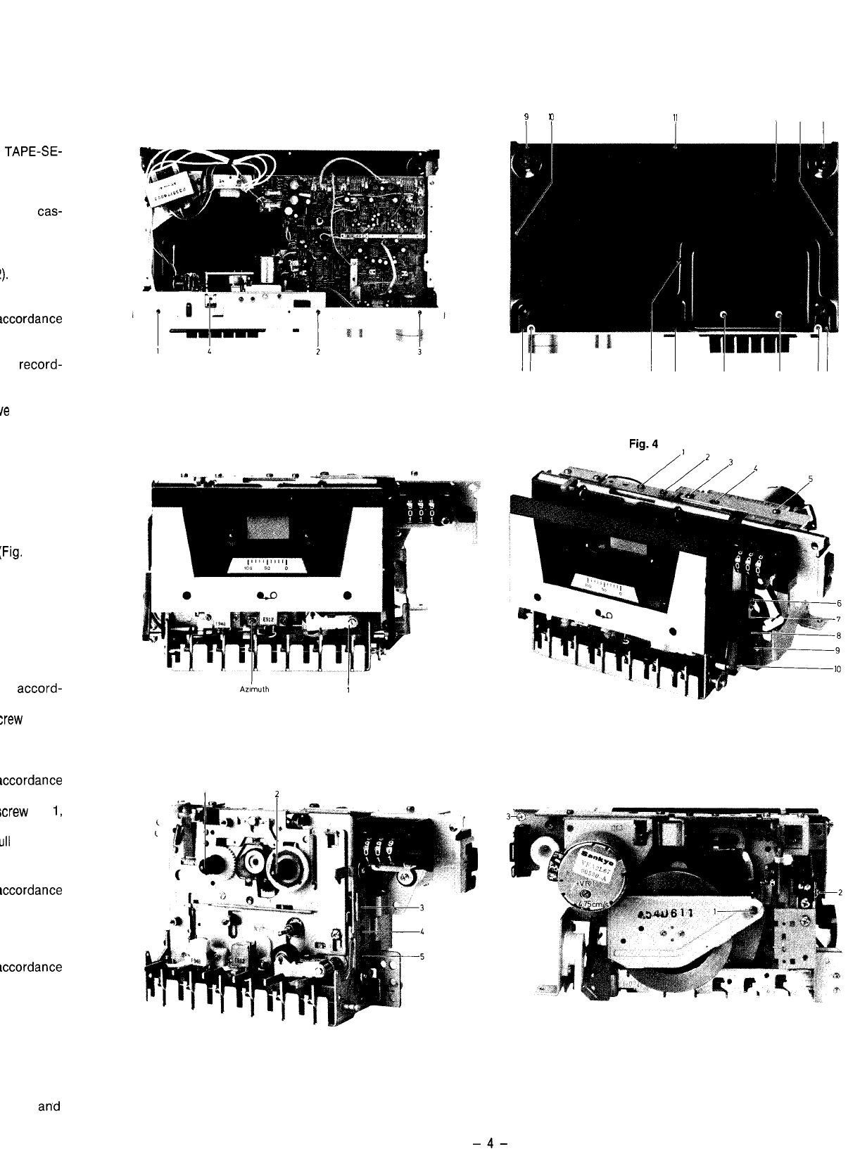
4. Einstellung des Azimuthwinkels
a) Testcassette 10000 Hz abspielen.
b) Mit der Justierschraube (Fig. 3) die
Ausgangs-
peqel
beider
Kanale
auf Maximum einstellen.
5. Einstellung des Wiedergabepegels
a) TAPE-SELECT-Schalter auf
Cr0.z
stellen.
b) DOLBY-Taste auf ,,AUS“.
c) Dolby 400 Hz-Cassette abspielen.
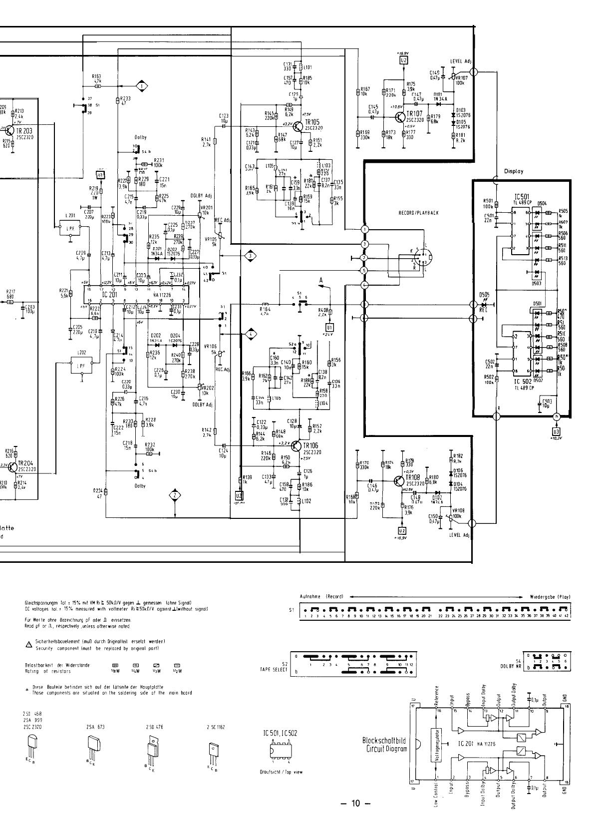
d) Mit den Potentiometern VR 101 (L) und VR 102
(R) am NF-Ausgang des Gerates 700
mV
+
0,5
dB
einstellen (siehe Fig. 9,10).
Achtung! Diese Einstellung wird fur den folgenden
Abgleich vorausgesetzt.
6. Einstellung der Aussteuerungsanzeige
a) TAPE-SELECT-Schalter auf
Cr02
stellen.
b) DOLBY-Taste auf ,,AUS“.
c) Dolby 400 Hz Cassette abspielen.
d) Mit den Potentiometern VR 107 (L) und VR 108
(R) die Anzeige so einstellen, da8 die 0-dB-LED
satt leuchtet, die 3-dB-LED jedoch
noch
dunkel
bleibt (siehe Fig. 9).
Test and Alignment Hints
Note:
Prior to any measurements all parts contacting the
tape, e.g. magnetic heads, guidings, capstan etc. have
tobe demagnetized. The alignment tools have to con-
sist of non-magnetizable material. Clean rubber pinch
roller and mirrors of head with alcohol, if necessary.
Attention! Filters L 201 and L 202 must not be tuned.
Measurement equipment required:
1. Audio-frequency oscillator 30 Hz
-
20 kHz, 0.5 V
output
2. Voltmeter with r.m.s. value display, f 2120 kHz,
RiLlMQ
3.
Wow and flutter meter
4. Test cassettes
a) Torque test cassette
(e.g. BP, Order No. 8627000356)
b) 3150 Hz- recording
c) 10000 Hz- recording
d) BASF DIN Ref. tape Fe, TP 18 Charge T 308 S
e) BASF DIN Ref. tape Cr, TP 18 Charge T 401
R
f) AGFA unrecorded referent tape
4.7513.81
FeCr
g) BASF Dolby-Level 400 Hz TM 60
5. Spring balance, 600 g
(e.g. BP, Order No. 8627000358)
1.
Measurement of contact pressure
The contact pressure of the rubber pinch roller is
measured at the roller axis by means of a string
balance. It should amount to 300-600 g. The rubber
pinch roller is to be slightly lifted by means of the
spring balance in playback for that purpose. If the
contact pressure is to low, replace rubber pinch
roller unit together with the spring contained in it.
2.
Measurement of tape tension
a) Load torque measurement cassette.
b) Set the unit to playback.
The torque should be 40-70
gem,
approximate.
3.
Adjustment of tape speed
a) Connect the wow and flutter meter and cali-
brate.
b) Playback test cassette 3150 Hz.
c) Adjust the nominal speed of 4.75 cm/set by
means of the potentiometer VRl (see Fig. 6) in
the motor. In this connection a drift of +1% and
a pitch variation of +0,2 % is acceptable.
4. Azimuth angle adjustment
a) Play-back the 10000 Hz test cassette.
b) Adjust the output levels of both channels to
maximum by means of the adjustment screw
(see Fig. 3).
5. Adjustment of reproduction levels
a)
Set TAPE SELECT switch to CrOz.
b) Set DOLBY-key to “OFF“.
c)
Play-back the 400 Hz Dolby cassette.
d) Adjust 700
mV
+-
0.5 dB at the AF unit output by
means of potentiometers VR 101 (L) and VR 102
(R) (see Fig. 9 and 10).
Attention: This adjustment is a requirement for the
following alignment.
6.
Adjustment of the recording level display
a) Set TAPE SELECT switch to
CrOn.
b) Set DOLBY-key to “OFF“.
c) Play-back 400 Hz Dolby cassette.
d) Adjust display by means of potentiometers
VR 107 (L) and VR 108 (R) such that the
O-dB-
LED is fully illuminated, and that the 3-dB-LED
is still dark (see Fig. 9).
Priif-
u’
7.
Einstc
a)
Prl
b)
D(
c)
DII
LE
d)
Gc
LE
m’
e)
NF
let
ne
ml
nE
bit
!ilE
8.
Einstc
a) Pr
b)
DI’
SE
c)
Gc
d) Mi
Mi
70
9.
Freqr
a) Pr
b) DI
SF
c)
D(
d)
Gc
Lf
3:
4
M
le
dc
f)
:;
Fc
g)
il
bc
10. DOL
4
P
b)
N
IE
cl
D
S
d)
G
4
D
f)
bJ
(1
9)
c
h)
h
;
-5-