manuals.online logo
Brands
  1. Home
  2. •
  3. Brands
  4. •
  5. Marantz
  6. •
  7. Cassette Player
  8. •
  9. Marantz CP230 User manual

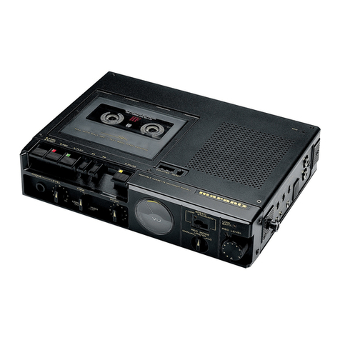
Marantz CP230 User manual

Other Marantz Cassette Player manuals
Marantz SD-63 User manual

Marantz

Marantz SD-63 User manual

Marantz SUPERSCOPE CD-320 Mounting instructions

Marantz

Marantz SUPERSCOPE CD-320 Mounting instructions

Marantz PMD510 User manual

Marantz

Marantz PMD510 User manual

Marantz SUPERSCOPE CD-320 Mounting instructions

Marantz

Marantz SUPERSCOPE CD-320 Mounting instructions

Marantz SD4050 /N1B User manual

Marantz

Marantz SD4050 /N1B User manual

Marantz PMD511 User manual

Marantz

Marantz PMD511 User manual

Marantz SD530 User manual

Marantz

Marantz SD530 User manual

Marantz SUPERSCOPE CRS-2204 User manual

Marantz

Marantz SUPERSCOPE CRS-2204 User manual

Marantz 5010 User manual

Marantz

Marantz 5010 User manual

Marantz SD-4051 User manual

Marantz

Marantz SD-4051 User manual

Marantz PMD201 User manual

Marantz

Marantz PMD201 User manual

Marantz PMD520/F1B User manual

Marantz

Marantz PMD520/F1B User manual

Marantz PMD211 User manual

Marantz

Marantz PMD211 User manual

Marantz PMD101 User manual

Marantz

Marantz PMD101 User manual

Marantz PMD222 User manual

Marantz

Marantz PMD222 User manual

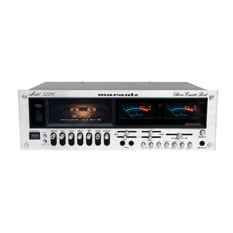
Marantz Professional PMD520 User manual
Marantz

Marantz Professional PMD520 User manual

Marantz PMD222 User manual

Marantz

Marantz PMD222 User manual

Marantz PMD201 User manual

Marantz

Marantz PMD201 User manual

Marantz cp430 User manual

Marantz

Marantz cp430 User manual

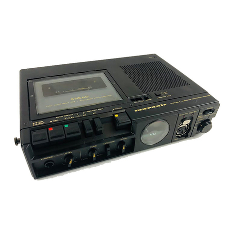
Marantz 5220 User manual

Marantz

Marantz 5220 User manual
Marantz 5025 User manual

Marantz

Marantz 5025 User manual

Marantz 5030 User manual

Marantz

Marantz 5030 User manual

Marantz PMD511 User manual

Marantz

Marantz PMD511 User manual

Marantz PMD201 User manual

Marantz

Marantz PMD201 User manual
Popular Cassette Player manuals by other brands

Ahuja CPA-360 Operation manual

Ahuja

Ahuja CPA-360 Operation manual

Sony Pressman TCS-60DV Specifications

Sony

Sony Pressman TCS-60DV Specifications

Philips AQ6485/14 Product information

Philips

Philips AQ6485/14 Product information

Sony TCM-200DV - Cassette Recorder operating instructions

Sony

Sony TCM-200DV - Cassette Recorder operating instructions

Nakamichi BX-300 Service manual

Nakamichi

Nakamichi BX-300 Service manual

Panasonic RQ-E25V operating instructions

Panasonic

Panasonic RQ-E25V operating instructions

Aiwa TP-VS535 operating instructions

Aiwa

Aiwa TP-VS535 operating instructions

Yamaha MT8X Operation manual

Yamaha

Yamaha MT8X Operation manual

Sherwood Newcastle D-480 operating instructions

Sherwood

Sherwood Newcastle D-480 operating instructions

Manta MA408 user manual

Manta

Manta MA408 user manual

GPO W0162B user guide

GPO

GPO W0162B user guide

Sony HST-471 Service manual

Sony

Sony HST-471 Service manual

Sharp JC-AV1 Operation manual

Sharp

Sharp JC-AV1 Operation manual

Pioneer CT-W103 Service manual

Pioneer

Pioneer CT-W103 Service manual

Sony CFS-B15 - Am/fm Stereo Cassette Recorder operating instructions

Sony

Sony CFS-B15 - Am/fm Stereo Cassette Recorder operating instructions

Sony WMFS220 - Portable Sports AM/FM Cassette... operating instructions

Sony

Sony WMFS220 - Portable Sports AM/FM Cassette... operating instructions

Aiwa HS-TA21 operating instructions

Aiwa

Aiwa HS-TA21 operating instructions

Sanyo MCD-ZX700F Service manual

Sanyo

Sanyo MCD-ZX700F Service manual

manuals.online logo
manuals.online logoBrands
  • About & Mission
  • Contact us
  • Privacy Policy
  • Terms and Conditions

Copyright 2025 Manuals.Online. All Rights Reserved.

MARANTZ
DESIGN
AND
SERVICE
Using
superior
design
and
selected
high
grade
components,
MARANTZ
company
has
created
the
ultimate
in
stereo
sound.
Only
original
MARANTZ
parts
can
insure
that
your
MARANTZ
product
will
continue
to
perform
to
the
specifications
for
which
it
is
famous.
Parts
for
your
MARANTZ
equinment
are
Snes
available
to
our
National
Marantz
subsidiary
or
Agent.
ORDERING
PARTS:
Parts
can
be
orderéd
either.
by
mall
or
by
telex.
mail,
fulfil
MARANTZ
order
forms.
MARANTZ
S.A.
EUROPEAN
PARTS
DEPARTMENT
(2,
Avenue
Léopola
tii.
B-7120
PERONNES-lez-BINCHE
.
BELGIUM.
TWX:
57589
SEPLT
B
In
both
cases,
MARANTZ
part
number
has
te
be
specified,
If
you
order
by
The
following
information
must
be
supplied
to
eliminate
delays
in
processing
your
order:
1.
Complete
address
.
Description
of
parts
Way
of
shipment.
SO
ee
PARTS
ORDERING:
Complete
part
numbers
and
quantities
required
Model
number
for
which
part
is
required
Parts
may
be
ordered
fram
the
following
addresses:
MARANTZ
S.A.
326
Avenue
Louise
Bte
32
1050
Bruxelles
Belgium
'
MARANTZ
AUSTRIA
Ge.M.B.H.
25
Franz
Liszigasse
2380
Perchtoldsdorf
Ausiria
~
MARANTZ
FRANCE
4
Rue
Bernard
Paltssy
92600
Asniéres
France
MARANTZ
REDERLAND
&.¥.
Wagenmackersweg
3
3449
H.V.
Woerden
’
Netherlands
©
EUROPE
MARANTZ
AUDIO
U.K.
LTD
Unit
15/16
- :
Saxon
Way
!ndustrial
Estate
Moor
Lane
Harmondsworth
UB7
OLW
Great
Britain
MARANTZ
BELGIUM
‘45
Rue
Auguste
Van
Zande
-4080
Brussels
Belgium
MARANTZ
GERMANY
G.NM.B.H.
Max
Planckstrasse
22
6072
Dreieich
1
Germany|
MARANTZ
SVENSKA
A.B.
Svartviksvagsn
56
Traéneberg
Bromma
Sweden
Signature:
any
order
form
or
aeex
must
be
signed
otherwise
such.part
order
will
be
aonaideted
as
null
and
void.
MARANTZ
AUSTRALIA
PTY
19
Chard
Road
;
Brookvale,
NSW
2100,
Australia
MARANTZ
DENAAARK
Bregneredvej
132b
3460
Birkerad
©
Denmark
-
MARAMT2Z
ITALIANA
S.p.A,
Via
Monte
Napcleone
10
~.
20121
Milano
ttaly
oe
All
of
the
above
locations
are
fully
equipped
to
taxe
care
of
your
total
service
ned:
Because
various
countries
have
differing
-
configuration
requirements,
it
is
necessary
that
you:
contact
the
service
facility
in
your
particular
country.
{nm
the
event
that
there
is
no
service
location
listed
for
your
country,
please,
contact
the
nearest
facility
for
a
necessary
assistance.
[~
In
case
of
difficulties;
do
not
hesitate
ta
contact
the
Technical
Department
at
abovementioned
address.
oe
‘SER
eR
eocn
ERED:
SECTION
INTRODUCTION
pe
ee
1,
2.
3.
oo
N
O
io
‘ELECTRICAL
ADJUSTMENTS
P.W.BOARDS
........
TEST
EQUIPMENT
FO
MECHANISM
AN
3.1
Overload
Prote
3.2
MIC
AMP
and
3.3
Auto:
PLAY
and-
Aw
3.4
Auto
Stop.
3.5.
Pitch
Contral,
shave
a
Record/Playba
“Freque
4.10
Alignment.
Points
Mirae
DIAGRAMS.
eee
&
5.1
Block/
Level
Diagrarns,
arson
5.2
Chip
Component
Locations
5.3
Wir
i
"g
Diagrams.
.
EXPLODED
VIEW.
AND
PARTS
LIST
ELCTRICAL
PARTS
LIS
TECHNICA’
ICA
SCHEMATIC
DIAGRAM
TABLE
OF
CONTENTS:
Ro
a
nr
ie
ae
ey
cere
et
a
ee
SA
eA
PP
BWWOW
O
NNNNNN
=
as
H
i
;
H
i
I
i
H
i
rf
i
i
-f
‘
i
i]
re
ME
St
Ane
oh
amb
mete:
Pant
ae
tte
neat
s
eeu
te
MODEL
CP230
STEREO
CASSETTE
RECORDER
ee
ng
aa
INTRODUCTION.
NIE
"SERVICING
This
service
manual
are
prepared
for
use
by
Authorized
Warranty
Station
and...
contains
service
information
for
Marantz
Stereo
Cassette.Recorder.
Servicing
information
and
voltage
data
included
in
this
—
manual
are
intended
for
use
by
the
knowledgeable
and
ex-
‘Audio
Oscillator
(AF
osc)
perienced
technician.
only.
All
instructions
should
be
read
+
Attenuator.
{600
ay
carefully.
No
attempt
should
be’
made
to
proceed
without
a-
-
@
Oscilloscope
»
good,
understanding.
of
1
the
opeaue:
of
the
Cassette
;
Recorder:
8
woos,
Boag
°
at
4
:
The
parts
ist
furnishes
frttonttiation’
‘by:
‘which,
rebiscanene
parts
may
be
ordered
from,
the,
Marantz:
Company.
Asimpie
description
is
included
for
parts:
which
can
be
usually
ob-”
tained
through
local
suppliérs.
1.
PW.
BOARDS
As
‘can
be
seen
from
the
‘circuit
diagram,
the
chassis
of
your
Cassette
Recorder
consists
of
the
following
units.
Each
unit,
mounted
on‘a
printed
circuit
board
is
described
ee
Hes
re
vor
le
Tape
See
d
oo
within
the
squaré
enclosed
by
a
bold
dotted
line
on
the
cir-
‘MTT-112
‘ 2
remerits
of
Output
Level
cuit
clagtar.
MIT-112B
MTT-150.
of
Output
Levet
ae}
on
P.W.
Board
P100
MTT-256
tor
Nerina
MT¥=121
MTT-4441
_
imounted
on
P:
W.
“Board
P700
:
mounted
on
P.W,
Board
P800
“I
motinted
.on
P.W:
Board
P900.
3.
MECHANISM
ANDES
CIRCUIT
T
DESCRIPTION:
J
tl
en--thi
AC
‘adapto
possible.
that
the
volt
é@
will
exceéd
this
amoun
level
for
the.
collector
bécomes
HIGH,
setting
amo?
to
‘ON
’
_
and
causing
the
current
to
flow
to
the
b
setiing
QM05
to
ON.
exceeds
5.5
olts,.
current
flows
at
‘the.
basé-of:
Qimo6
“the
signal
Jevel
at
the
collector:
becomes:
LOW:
and
QM07.
shuts:
OFF.
‘Current
low
into:
‘QM05.:
-The
‘current
is
output
at
Vo:
by
‘stabilized.
‘power.
constructed
in
OMO04
‘and:
amos,
The:
voltage
aches.
srproximarely:
4.5:
yore
by
the
voltage
from
Qmo
3.
ae
phase
ampli
adjusti
op
oO
the
amplifier,
‘When
OaB
nters
by
way
of:
@
and
@
at
-SIQF
0111,
211,
ari2and
O21
At
—15dB
the
level
beco
nés
HIG
¢
circuit:
t:
for
the
mic
‘amp
is
a
low
noise,
positive:
.
2and
maximum
en
is
achieved.
fe
rewin
pressed
and
docked
in.
‘place,
the.
lock
‘releases.
w
counter.
reaches:
“900”
and
the
PLAY
mode
is
ente
When
the
tape.
has
finished
*
“winding:
in
both
‘modes,
before
the
counter
reaches
the
respective
‘positions,
‘the
AUTO"
STOP
function
and
all
buttons.
are.
released,
Also:
when
the
RE-
WIND
butto
!
"9997",
The’
same
_abolies
ast:
foward
:
‘Operation.
which
Stops
at
900",
Whi
counter:
‘Ts:
between:
“900'”°and
“1999""
‘bo
‘ing
F
utton
will
lock
welt
preésed:
‘When:
counter:
reaches:
999,
he
rewind
-
tock:
celeases-
and
the
PLAY,
ope
s
SR
erence
emery
Se
ynm
ne
ee
cent
es
er
ts
eee
Trea
came
annie
Pest
se
ay
es
4,
ELECTRICAL.
ADJUSTMENTS
ay
é
Precautions
for
Adjustment
and
Measurement
ae
2.
Do
riot
place
the
test
tape
on
any
mea
3.
Do
not.
put
the
test
tape’
near,
a
pl
used.
ng
instrument,
re
‘the
‘eraser
is
4.
Method
of
Demagnetization:
;
Turn.
hee
eraser
power.
switch
on
at
a
position.
far.
awa}
the
heads,
Bring
the
eraser
close
to
the
heads,
caps
n
and.
other
parts
to-
be
demagnetized,
and
move:
it
and.
down
four
o¢
five
times
to’
demagnetize.
Slowly
separate
the
eraser
far
—
away
from
the
parts,
and
twrn.the:
power.
switch
off.
5.
Do
not
use
any
magnetized
adjusting
tool,
hi
necessary,
:
3.
After
Lannuhene:
japent
the
slavbak
and
stop
settings
several
times
to
Leann
no
3
alliage
deviation.
.
4.2
ae
Speed
Ad
peels
Mode:
‘Playback
meade
Frequency.
Test.
requ
te
ae
Counter
©
|.
SkHz
‘Line
Guiput
:
ies
Piay
the
316H2
‘signai
oft
thet
test
tape
MTT
256
back.
;
The
VIVM
at
tlio
4.4
Playback
Level
Adjustment
1.
Adjust
the
a
‘Selector
Switch
t
‘to
)
NORMAL
and
turn
the
NR
switch
OFF,
us
:
-
2.
Play
the
test
tape
MTT-150
back;
Adjust
RIMO{L}.
and
R210(R)
so
that
the
voltage.
of
OA02
©
pin
and
@
pin
.
™
ke
sure,
the
voltage
‘of
-
is
100mV.
In
this.
operation,
LINE
OUT
reads
550mV
+
10B.
NOTES:
ve
3S
1.
Proceed
both
for
the
nic
way.
2.
For:
details
refert
to
:
Mode:
Palyback.
; ; |
HRN
a
OME
ae
:
Test
Tape.
2.
2
YTV
MTT-150
:
ott
ey
I
ey
steneyeerpen
ie
eet
ge
Raia
4.6
Playback
Noise
Measurement
1.
Set.
the
selector
Switch
to
NORMAL
and
NR
switch
to
OFF.
:
:
oe
2..
Play
back
the
blank
fape
sand
make
sure
that
the
noise
volume
is
below
2mV
when
the
REC
LEVEL
Knob
is
set
to.
both:
maximum
and
minimum.
NOTES:
sae
1.
Perform
measurements
when
the
power
hum
is
at
mini-
mum,
aera
2.
Perform
measurements
under
conditions
where.
induc-
tion
noise
will
not
affect
measurements.
4.7
MPX
Filter
Measurement
po
=
>
4.
.
Adjust
the
Tape
Selector
Switch
to
NORMAL.
.
Put
the
blank
tape
in
the
‘cassette
holder,
and
set
the
recording
conditions.
(Dolby
NR
“ON”,
MPX
“ON”
positions):
.
Add
a
1kHz
20dB
5
signal
to
LINE
IN.
Adjust
the
Rec.
Volume
knob
to
0dB
Level
Meter
reading.
.
Set
the
input
signal
at
19kHz
+10Hz.
Adjust
T101
(L)
and
T201
(R)
to
the
minimum
level.
Mode:
record
TONE:
1-kHz,
100mV
,
Lk
Line
Input
Line
Output
8
Record/Playback
Level
Adjustment
.
Set
the
tape
selector
switch
to
NORMAL.
Insert
the
AC-212
test
tape
in
the
cassette
holder
and
set
the
specified
recording
condition
(LINE
OUT:
350mV).
Adjust
R119(L)
and
R219(R)
to
the
same
level
as
the
monitoring
level
when
the
tere
is
s
played
back
after
rewinding.
;
As
for
CrO;/METAL
tapes,
mikes
measurements
with
the
AC-512
and
AC-711
test
tapes
as
described
above.
9
Record/Playback
Frequency
|
Response
Ad-
justment
[NORMAL]
1.
~
NR
“ON”
and
MPX
“OFF")
Set
the
tape
selector
switch
to
NORMAL
-
(with
Dolby
2.
insert
the
AC-212
test
tape
in
the
cassette
holder
and
set
the
recording
conditions.
Attenuate
from
550mV_
to
25dB
on
Line
Out
with
the
attenuator
and:
record
at
~
AKHz
and
10KHz
on
an
unrecorded
section
of
the
tape.
.
Rewind
the
tape
and
adjust
CBO1(L)
and
“CB02(R)
so
that
the
level
for
1KHz
and
10KHz
is
brought
within
+0.5dB
for
playback.
,
After
making
these
adjustment,
record
and
slaybeck
at
1KHz,
10KHz
and
12.5KHz.
Make
sure
@
results
comply
with
the
following
diagram.”
a
NR
“OFF”.
lOKH2z::
apart
i2SKHz
0
[CrO,
1.
2.
Set
the
tape
selector
switch
to
CrO,...:
Insert.
the
AC-512
test.
tape
in
the
cassette
holder
and
set
the
recording
conditions.
Attenuate
from
550mV
to
25dB:
on
Line
Out’
with
the
attenuator
and
record
at
1kHz,
.10kHz,
12.5kHz
and
7
Ke.
on
an
unrecorded
section
of
the
tape.
~
Rewind.
the
tape and.
adjust
CBO1(L)
and
CB02(R)
so
that
the
level.
for.
1kHz
and
1OKH2
is
brought.
within
+0.5dB
for
playback:
.
After
making
these
adjustments,
cord
and
playback
at
1kHz,
10kHz,
12.5kHz
and
15kHz.:
Make
sure
results
comply
with
the
following
diagram.
NR
OFF”
Hz.
12,
5KHz
ISKHz
SdB
.
250Hz
1OKHz
12,
5KHz
eee
scape
meson
[METAL]
:
a
ee
.
Adjust
the
T
ape
Selector
Switch
to
M
ETAL.
ce
ne
2,
Load
the
test
tape
AC-711
into
cassette
holder.
Perform
_Measurements
as
with
CrO,,
and
make
sure
they
con-
_formwith
the
Chartinright.
7
NOTE:
Adjustment
points
for
NORMAL,
‘CrOz,
METAL
are
egies
al
PES
common
with
CBO1(L)'and
CBO2(R).
$48
;
eh
:
se
peo
ES
OR
St
oa
tans
Alignment
Points
&
|
ee
eee
5.
DIAGRAMS
52
5.1.
Block/Level
Diagrams
[RECORDING
MODE]
LINE
OUT
LINE
IN
JO2
(dBV
)
@)
(6)
[PLAYBACK
MODE]
MTT-150
400Hz
200
nwb/m
QAO!
QAO
HEAD
PHONE
LINE
AMP
RVO!
Chip
Component
Locations
wrsearvetie,
BE
tl
er
WE
ernie
H
cd
oo
rr
kei,
a
Macsitumrananetintttertensan’
ne
Atma
cat
rsenancl
Fine
Spe,
Ry,
s,,
tdanetemenmannnaracnnanmaae
artery
Ae
EEE“
aecticatg
emer
te
mm
Dg
{
nce
d
Nar,
Sg
|
—
:
<P
oe
a
eS
ie,
Rosemarie
~
:
.
a
(
c
ee
-
ms
SSG
or
ee
sata!
BN
=
am
es
i
5.3.
Wiring
Diagram
TAPE
COUNTER
MOTOR
MO7I
RIGHT
LEFT
so7l
YEL
POWER
SW
YEL
PLAY
SW
SO73-2
PAUSE
SW
S074
STOP
SW
SO73-}
ERASE
HEAD
JH72
FF/REW
$o72
SPEAKER
NOO3
JO0O3
stp
pig
aeons
SUMIX3
JOO4