Bosch D5060 User manual

Multiplex Point Programmer D5060
User’s Guide May 2004
1.0 Introduction
Use the multiplex point programmer (Figure 1 and
Table 1) to program multiplex bus points for the Bosch
Security Systems D9412G, D9412, D9112, D7412G,
D7412, D7212G, and D7212 Control Panels. In
addition to programming points, the D5060 can also
be used to program and read information from a
D8125MUX.
Figure 1: Multiplex Point Programmer
EXT.
POWER SERIAL PORT MUX
POINTS
INTERROGATION MODE
ON
(HOLD)
YES NO
DOWN UP
CLEAR ENTER
OFF
(HOLD)
INTERROGATE
(HOLD)
MULTIPLEX POINT PROGRAMMER
13
456
7 8 9
*
0#
2
Table 1: D5060 LED Display Definitions
Display Definition
Adr Enter address
A.dr Enter address for Interrogation Mode
bAd Battery voltage is below 15 V
Err Point was not programmed correctly
Lob Battery voltage is below 16 V
noP No response from point
PnL Communications with the D8125 failed
rSP Point responds to address
tYP Enter point type
t.YP Enter point type for Interrogation Mode
2.0 Installation
1. If using external power, attach the flying leads of
the included power cable to the output terminals
of a 16.5 VAC transformer. Insert the plug end
into the jack labeled EXT. POWER on the
programmer. Refer to Figure 2, Figure 3, and
Figure 4.
2. For control panels, use the serial cable provided
to connect the D8125MUX to the D9412G,
D9412, D9112, D7412G, D7412, D7212G, or
D7212 Control Panel to the jack labeled SERIAL
PORT on the programmer.
3. For MUX devices without DIP switches, use the
multiplex programmer cable provided to connect
the point to be programmed to the port labeled
MUX POINTS as shown in Figure 2. Use the
appropriate connector, either the alligator clips or
the probes, to connect the programmer to a point.
For MUX devices with DIP switches, program
the point using the DIP switches. Connect the
programmer to the D8125 MUX as shown in
Figure 3, using the C318 serial cable (Figure 4) to
program the point number and point type into
the D8125MUX.
Figure 2: Wiring Diagram When Installing MUX
Points Without DIP Switches
EXT.
POWER SERIAL PORT MUX
POINTS
INTERROGAT IONMODE
RESE T
12V IN OU T GND
ZONEX BUS FIRE MANUAL
WALKTEST PROG
PORT +-+- + - +-
POWER A MUXB US A POWER B M UXB US B
1
4
3
2
1 - External power
2 - D8125 MUX
3 - MUX point without DIP switches (non-i
models)
4 - D5060 Multiplex Point Programmer

D5060
D5060 User's Guide
F01U034899_02 Page 2 © Bosch Security Systems B.V., 2021
It is not necessary to connect a MUX
module to the D5060 to program MUX
points with programming DIP switches.
Figure 3: Wiring Diagram When Installing MUX
Points With DIP Switches
EXT.
POWER SERIAL PORT MUX
POINTS
INTERROGATION MODE
RESET
12V IN OUT GN D
ZONEXBUS FIRE MANUAL
WALKTEST PROG
PORT +- +- + - +-
POWER A MUXB US A POW ER B M UX BUS B
1
3
2
1 - External power
2 - D8125 MUX
3 - D5060 Multiplex Point Programmer
Figure 4: Cables Included with the Programmer
1
3
2
1 - C318 Serial Cable
2 - C319 External Power Supply Cable
3 - C320 Multiplex Programmer Cable
3.0 Programming
Procedure
3.1 Powering the D5060
To turn the D5060 on, press and hold the [1] key until
the unit beeps. To turn the unit off, press and hold the
[#] and [*] keys simultaneously until the unit beeps.
After 5 min of inactivity, the programmer
powers down automatically to conserve
power.
3.2 Programming the Points
1. The D5060 displays the prompt Adr after it is
powered on. This indicates that it is ready to
begin programming.
2. If the MUX device has no DIP switches, connect
the D5060 to the point to be programmed (Figure
2). If the MUX device has DIP switches, program
the device using its DIP switches.
The point must be connected only to the
programmer and not to the D8125MUX or
the MUX bus.
If programming points for a Bosch
Security Systems control panel, and if the
MUX device has no DIP switches,
connect the D8125MUX and the MUX
device to be programmed to the D5060
for simultaneous programming (Figure 2).
If the MUX device has DIP switches,
program the device using its DIP
switches.
3. Enter the point’s three-digit address. The address
must be between 1 and 255. Press [#].
4. The programmer displays tyP. Enter the number
corresponding to the point type you are
programming (Table 2), then press [#]. The
programmer alternately displays the address and
the point type.
When programming a Mux Smoke point
(decimal value 4 or 5, as shown in Table
2), an 18-second timer starts counting. Do
not disconnect the Mux Smoke point until
after the timer counts down to zero.

D5060
D5060 User's Guide
© Bosch Security Systems B.V., 2021 Page 3 F01U034899-02
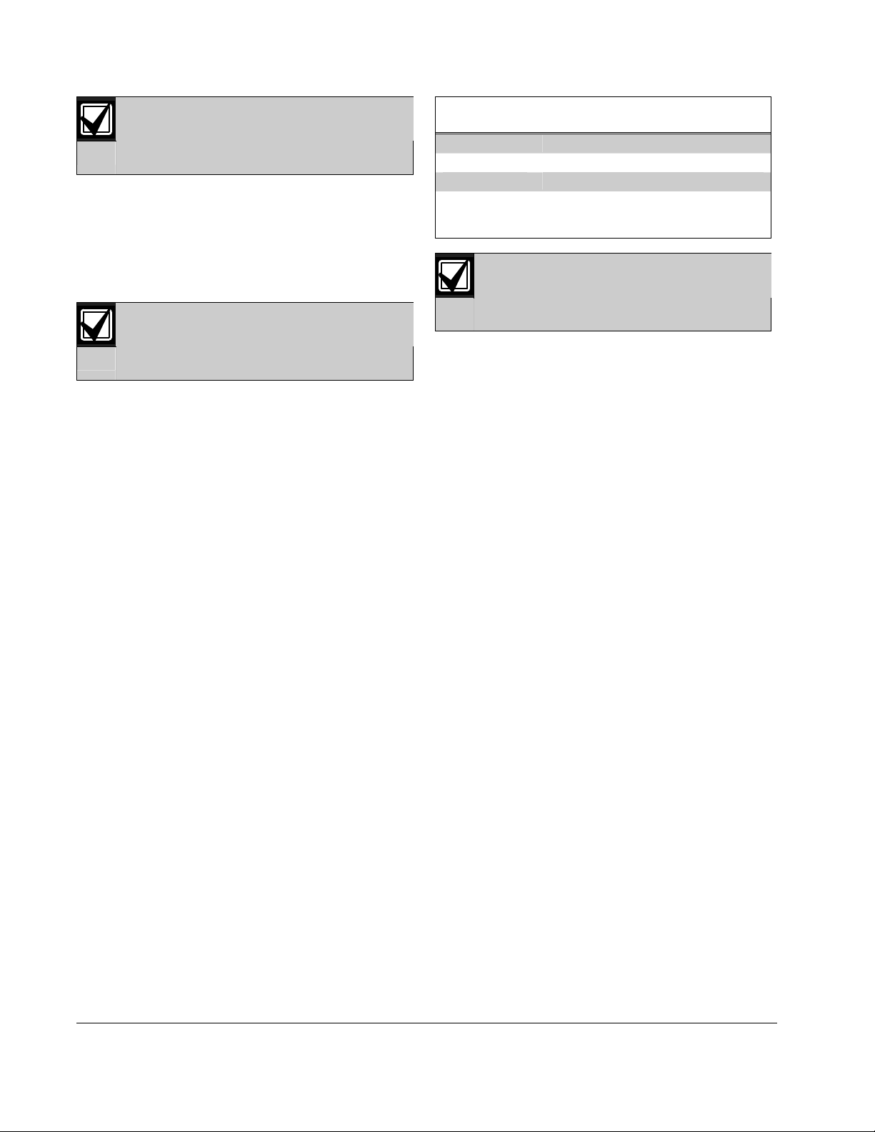
Table 2: Point Type Entry Code
Decimal Value Point Type
0 Remove point from D8125MUX
1 Contact
2 Sensor (or Single Point Module)
3 I/O Module
4 Mux smoke without low temperature
5 Mux smoke with low temperature
6 Dual point
5. Press [#] to program a point connected to the
D5060 and the D8125MUX (if connected), or
press [1] to program the D8125MUX only. If the
MUX device has DIP switches, program the
device using its DIP switches.
Press [*] at any time to back up through
the sequence.
6. If the point is programmed correctly, the unit
beeps once and displays Adr indicating that it is
ready to program the next point. If the point was
not programmed correctly, the unit sounds a
three-beep error tone and one of the following
messages displays:
Err: The point was not programmed correctly.
PnL: Communications with the D8125MUX
failed.
7. Press [*] to clear the entry, or press [#] to
reprogram.
3.3 Removing a Point from the
D8125MUX
1. Apply power to the D5060 and connect the
programmer to the D8125MUX only.
2. Enter the address of the point you wish to
remove.
3. When prompted for a point type, press [0]. Refer
to Table 2.
4.0 Interrogation Mode
You can also use the programmer to read information
from a D8125MUX and from MUX points. Refer to
Section 2.0 Installation for D5060 installation
information.
4.1 Reading Information from the
D8125MUX
1. To put the unit into Interrogation Mode, press
and hold [7] and [9] simultaneously until the unit
beeps. The LED marked INTERROGATION
MODE lights.
2. The display shows A.dr and the left-most
decimal point lights, prompting the user to enter a
starting address. Enter an address followed by [#].
3. The Interrogation LED flashes. Press [#] to read
point information from the D8125MUX at that
address.
4. Press [4] to read the previous address information
from the D8125MUX.
5. Press [6] to read the next address information
from the D8125MUX.
If communication between the unit and the
D8125MUX fails, the unit sounds a three-
beep error tone and displays PnL.
6. To exit Interrogation Mode, press and hold [*]
until the unit beeps.
4.2 Reading Information from MUX
Points
Disconnect all multiplex points from the
D8125MUX and the multiplex bus before
reading multiplex point information.
1. To put the unit into Interrogation Mode, press
and hold [7] and [9] simultaneously until the unit
beeps. The LED marked INTERROGATION
MODE lights.
2. The display reads A.dr and the left-most decimal
point lights, prompting you to enter a starting
address. Enter an address and press [#].
3. Press [1].
4. When
t.YP displays at the keypad, enter the
point type of the Mux point (Table 2) and press
[#].
5. If a point responds to the address, the
programmer beeps once and displays rSP. If the
point does not respond, the unit beeps three times
and the display reads noP.
6. To exit Interrogation Mode, press and hold [*]
until the unit beeps.

© Bosch Security Systems B.V., 2021
Torenallee 49 5617 BA Eindhoven, Netherlands
F01U034899-02
User's Guide
2021.07
D506
0
Page 4 of
4
5.0 Batteries
This device is intended for use with AC
power. Extended use of batteries is not
recommended due to the power
requirements of the unit.
This unit includes a feature that monitors the charge
of the batteries. If the battery voltage falls below 16 V,
the unit displays Lob. If the battery voltage falls below
15 V, the unit displays bAd. The display of Lob or
bAd indicates insufficient power for programming.
D8125MUX communications might still function
properly even if these conditions exist.
To preserve the life of the batteries,
remove them from the multiplex point
programmer whenever you will not use the
unit for any length of time.
6.0 Specifications
Table 3: Specifications
Description Value
Display Three-digit, seven-segment LED
Power 16.5 VAC (20 VA to 50 VA) external
power source (recommended), or two
9 VDC batteries (optional)
This product is intended for use with AC
power. Extended use of batteries is not
recommended due to the power
requirements of the unit.
Other Bosch Motherboard manuals