Bosch BME280 User manual

BME280 User Manual
Document revision
1.0
Document release date
April 2023
Document number
BST-BME280-DSxxx-yy
Sales Part Number
0 273 141 185
Notes
Data and descriptions in this document are subject to change without notice. Product
photos and pictures are for illustration purposes only and may differ from the real
product appearance.
BME280
Desktop Development 2.1 User Manual

Bosch Sensortec | BME280 User Manual 2 | 23
© Bosch Sensortec GmbH 2023 | All rights reserved, also regarding any disposal, exploitation, reproduction, editing, distribution, Document number: BST-BME280-DSxxx-yy
as well as in the event of applications for industrial property rights
Table of Contents
1 About user manual .........................................................................................................................................................4
1.1 Who should read this manual................................................................................................................................4
1.2 DD2.1 UI Overview................................................................................................................................................ 4
1.3 Sensor Communication: ........................................................................................................................................ 4
1.4 Graphical display: ..................................................................................................................................................4
1.5 Data logging: .........................................................................................................................................................4
2 About the BME280......................................................................................................................................................... 5
3 Getting Started ..............................................................................................................................................................6
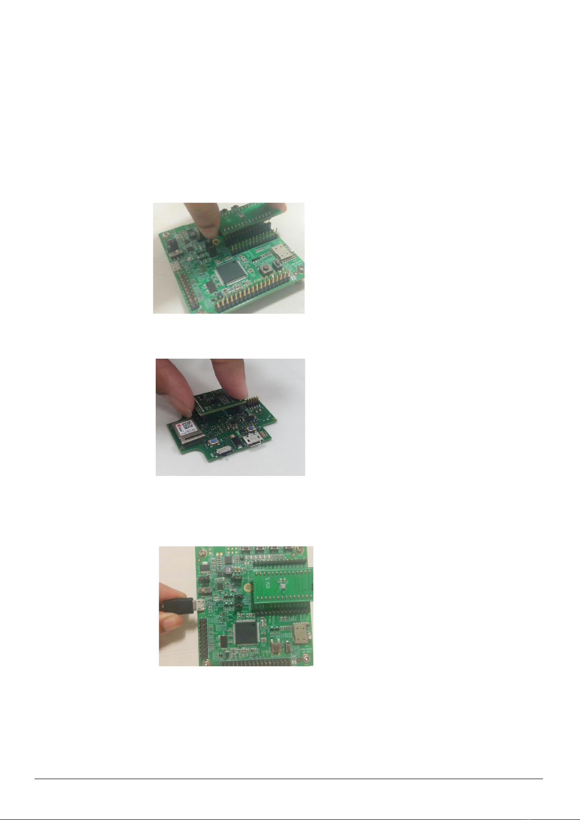
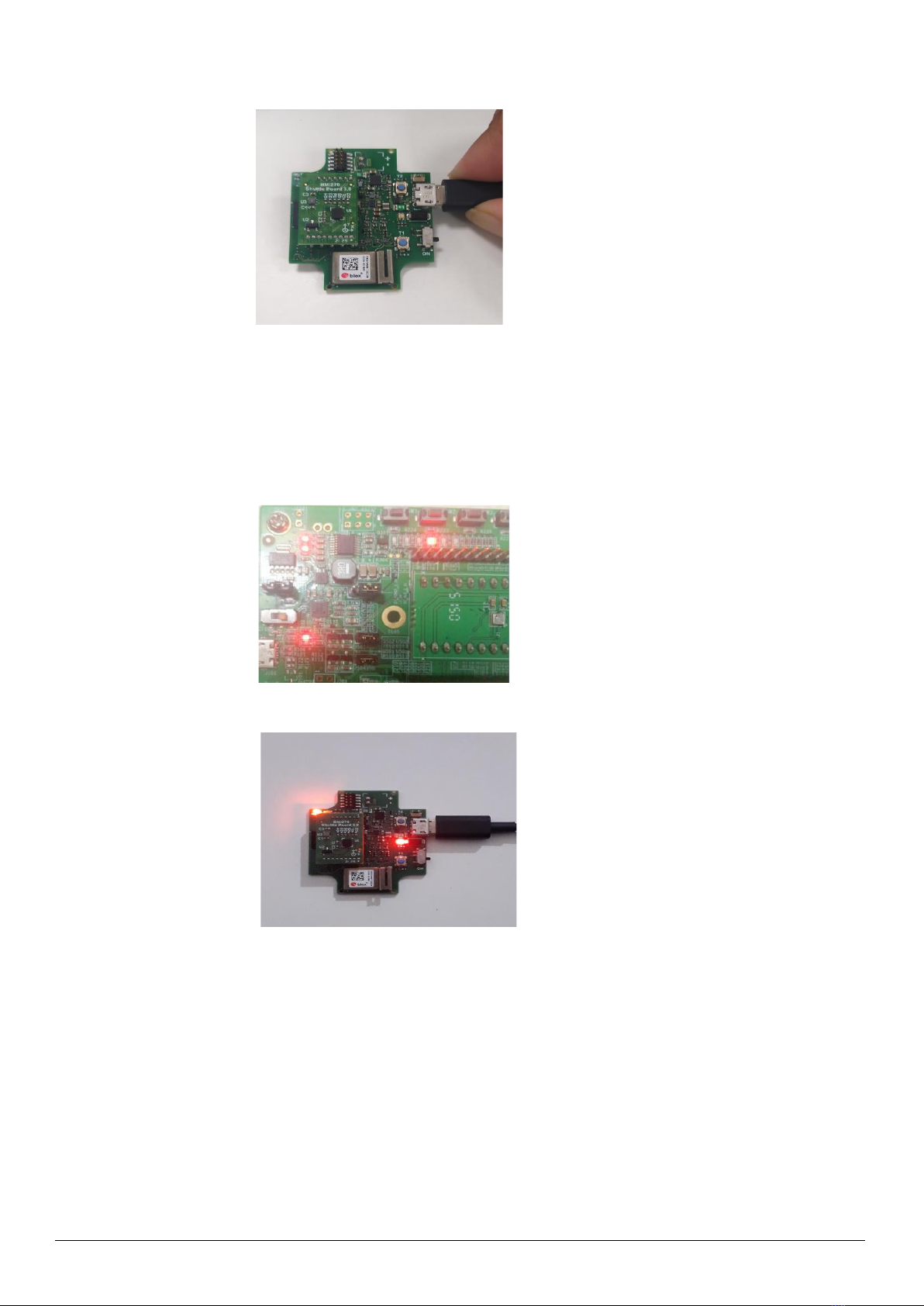
3.1 Setting Up the board-PC connection.......................................................................................................................6
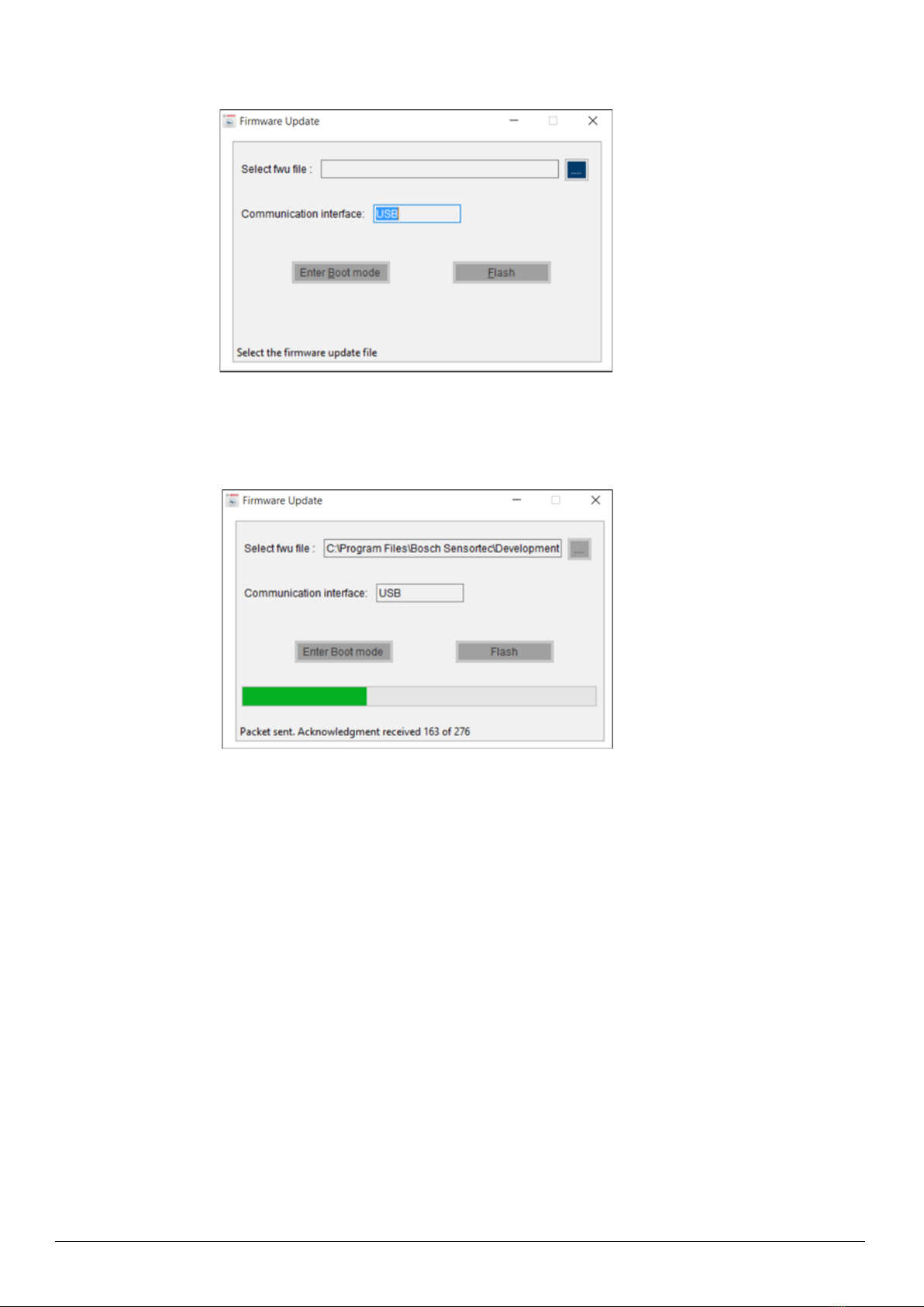
3.2 Upgrading Firmware ................................................................................................................................................9
3.2.1 For App 2.0 Board: ......................................................................................................................................... 9
3.2.2 For App 3.0 Board: ......................................................................................................................................10
4 Working with DD2.1 UI ................................................................................................................................................ 12
4.1 Sensor Data...........................................................................................................................................................12
4.1.1 Altitude..........................................................................................................................................................12
4.1.2 Relative Humidity .........................................................................................................................................12
4.1.3 Temperature ................................................................................................................................................. 12
4.2 Default View........................................................................................................................................................... 13
4.3 Memory Map..........................................................................................................................................................13
4.4 Sensor Mode .........................................................................................................................................................14
4.5 General Settings: ...................................................................................................................................................14
4.6 Reset Sensor .........................................................................................................................................................16
4.6.1 PO Reset ...................................................................................................................................................... 16
4.6.2 Soft Reset..................................................................................................................................................... 16
4.7 Data Export/ Log....................................................................................................................................................16
4.8 Register Access................................................................................................................................................... 17
4.9 Calibration ........................................................................................................................................................... 17
5General Troubleshooting............................................................................................................................................ 18
6Legal disclaimer ..........................................................................................................................................................21

Bosch Sensortec | BME280 User Manual 3 | 23
© Bosch Sensortec GmbH 2023 | All rights reserved, also regarding any disposal, exploitation, reproduction, editing, distribution, Document number: BST-BME280-DSxxx-yy
as well as in the event of applications for industrial property rights
7Document history and modification.......................................................................................................................... 22
List of figures
Figure 1 : Insert sensor for APP2.0 ................................................................................................................................... 6
Figure 2 : Insert sensor for APP3.0 ................................................................................................................................... 6
Figure 3 : Connect board and PC for APP2.0 ................................................................................................................... 6
Figure 4 : Connect board and PC for APP3.0 ................................................................................................................... 7
Figure 5 : Connection complete for APP2.0 ...................................................................................................................... 7
Figure 6 : Connection complete for APP3.0 ...................................................................................................................... 7
Figure 7 :: DD2.1 UI Startup View ..................................................................................................................................... 8
Figure 8 : Communication Status ...................................................................................................................................... 8
Figure 9 : Firmware upgrade window ................................................................................................................................ 9
Figure 10 : Application Boot Loader .................................................................................................................................. 9
Figure 11 : Boot mode Detected ..................................................................................................................................... 10
Figure 12 : Firmware upgrade completion ...................................................................................................................... 10
Figure 13 : Firmware upgrade window ............................................................................................................................ 11
Figure 14 : Firmware upgrade completion ...................................................................................................................... 12
Figure 15 : Memory Map ................................................................................................................................................. 14
Figure 16 : Measurement Settings .................................................................................................................................. 15
Figure 17 : Sensor Metrics .............................................................................................................................................. 16
Figure 18 : Data Export ................................................................................................................................................... 17
Figure 19 : Register Access ............................................................................................................................................ 17
Figure 20 : Calibration window ........................................................................................................................................ 18
Figure 21 : Selecting USB device corresponding to application board ........................................................................... 19
Figure 22 : USB driver installation................................................................................................................................... 19
List of tables
Table 1 : The technical specifications of the BME280 sensor .......................................................................................... 5
Table 3 : General TroubeShoot....................................................................................................................................... 20

Bosch Sensortec | BME280 User Manual 4 | 23
© Bosch Sensortec GmbH 2023 | All rights reserved, also regarding any disposal, exploitation, reproduction, editing, distribution, Document number: BST-BME280-DSxxx-yy
as well as in the event of applications for industrial property rights
1 About user manual
This manual describes the installation and usage of the Development Desktop 2.1 User Interface (DD2.1 UI); a
Windows based PC software application and related embedded firmware/software developed by Bosch Sensortec for
demonstration and evaluation of sensors.
1.1 Who should read this manual
This information is intended to users who wish to use the BME280 sensor alongside DD2.1 UI to
graphically display the Indoor Air Quality (IAQ), relative humidity, altitude, and associated components.
1.2 DD2.1 UI Overview
DD2.1 UI is a PC based software used to read, capture, and display sensor data. To display the sensor data of
BME280 on DD2.1 UI, mount the sensor on the Bosch Sensortec application board. This is a universal demonstration
environment for Bosch Sensortec sensor products.
Bosch Sensortec sensors are mounted on sensor specific shuttle boards. All sensors shuttle boards have an
identical footprint and can be plugged into the application board’s shuttle board socket. DD2.1 UI automatically detects
the sensor that has been plugged in and starts the corresponding software application.
1.3 Sensor Communication:
DD2.1 UI software supports both SPI and I2C to communicate with the sensor.
1.4 Graphical display:
DD2.1 UI displays the sensor data and interrupts in different graphical formats.
1.5 Data logging:
DD2.1 UI offers data logging of the sensor data.

Bosch Sensortec | BME280 User Manual 5 | 23
© Bosch Sensortec GmbH 2023 | All rights reserved, also regarding any disposal, exploitation, reproduction, editing, distribution, Document number: BST-BME280-DSxxx-yy
as well as in the event of applications for industrial property rights
2 About the BME280
The typical applications that use BME280 are:
• Context awareness, e.g. skin detection, room change detection
• Fitness monitoring / well-being
• Warning regarding dryness or high temperatures
• Measurement of volume and air flow
• Home automation control
• control heating, venting, air conditioning (HVAC)
• Internet of things
• GPS enhancement (e.g. time-to-first-fix improvement, dead reckoning, slope detection)
• Indoor navigation (change of floor detection, elevator detection)
• Outdoor navigation, leisure and sports applications
• Weather forecast
• Vertical velocity indication (rise/sink speed)
The targeted devices that use BME280 are:
• Handsets such as mobile phones, tablet PCs, GPS devices
• Navigation systems
• Gaming, e.g flying toys
• Camera (DSC, video)
• Home weather stations
• Flying toys
• Watches
Table 1 : The technical specifications of the BME280 sensor
Parameter
Technical Data
Package Dimensions
8-Pin LGA with metal
2.5 x 2.5 x 0.93 mm³
Operation Range (full accuracy)
Pressure: 300...1100 hPa
Temperature: -40…85°C
Supply Voltage VDDIO
Supply Voltage VDD
1.2 ... 3.6 V
1.71 ... 3.6 V
Interface
I²C and SPI
Average current consumption
(1Hz data refresh rate)
1.8 μA @ 1 Hz (H, T)
2.8 μA @ 1 Hz (P, T)
3.6 μA @ 1 Hz (H, P, T)
T = temperature
Average current consumption in
sleep mode
0.1 μA
Pressure sensor
RMS Noise
Sensitivity Error
Temperature coefficient offset
0.2Pa (equiv. to 1.7cm)
±0.25% (equiv. to 1m at 400m height change)
±1.5Pa/K (equiv. to ±12.6cm at 1 °C temperature
change)
Humidity sensor:
Response time (τ63%)
Accuracy tolerance
Hysteresis
1 s
±3% relative humidity
≤2% relative humidity

Bosch Sensortec | BME280 User Manual 6 | 23
© Bosch Sensortec GmbH 2023 | All rights reserved, also regarding any disposal, exploitation, reproduction, editing, distribution, Document number: BST-BME280-DSxxx-yy
as well as in the event of applications for industrial property rights
3 Getting Started
The below sections highlight the procedure to set up connections between BME280, DD2.1 UI , and the PC.
3.1 Setting Up the board-PC connection
The procedure to connect sensor to PC via USB is as below:
Install DD2.1 UI
Insert the shuttle board and application board.
Figure 1 : Insert sensor for APP2.0
Connect the board and PC using a USB cable/Bluetooth.
Figure 2 : Insert sensor for APP3.0
Figure 3 : Connect board and PC for APP2.0

Bosch Sensortec | BME280 User Manual 7 | 23
© Bosch Sensortec GmbH 2023 | All rights reserved, also regarding any disposal, exploitation, reproduction, editing, distribution, Document number: BST-BME280-DSxxx-yy
as well as in the event of applications for industrial property rights
Turn the on/off switch ON. The LED glows.
Figure 5 : Connection complete for APP2.0
Figure 6 : Connection complete for APP3.0
To start the DD2.1 UI software:
Click Start -> Programs -> Development Desktop 2.1.
Or
Double click the DD2.1 UI software icon on the desktop.
The Graphical User Interface (GUI) of the software is as seen below:
Figure 4 : Connect board and PC for APP3.0

Bosch Sensortec | BME280 User Manual 8 | 23
© Bosch Sensortec GmbH 2023 | All rights reserved, also regarding any disposal, exploitation, reproduction, editing, distribution, Document number: BST-BME280-DSxxx-yy
as well as in the event of applications for industrial property rights
Figure 7 :: DD2.1 UI Startup View
When the PC and board are connected, the Communication Status glows green as shown below:
Figure 8 : Communication Status
•The communication status is also indicated at the bottom right of the GUI at all times:
•Other menu options include:
▪File
▪Interface Selection
▪Panels
▪Settings
▪Help
These menu options are explained in detail in the following sections.

Bosch Sensortec | BME280 User Manual 9 | 23
© Bosch Sensortec GmbH 2023 | All rights reserved, also regarding any disposal, exploitation, reproduction, editing, distribution, Document number: BST-BME280-DSxxx-yy
as well as in the event of applications for industrial property rights
3.2 Upgrading Firmware
3.2.1 For App 2.0 Board:
To upgrade the firmware of DD2.1 UI to match the current version, follow the steps below:
Click Menu -> Settings-> Firmware Upgrade. The following window appears:
Figure 9 : Firmware upgrade window
Click Enter Boot mode.
▪Switch off board, and press Switch 2.In Application board, all four LEDs will glow simultaneously.
▪Click OK.
▪All four LEDs will glow simultaneously.
▪Press OK.
Figure 10 : Application Boot Loader

Bosch Sensortec | BME280 User Manual 10 | 23
© Bosch Sensortec GmbH 2023 | All rights reserved, also regarding any disposal, exploitation, reproduction, editing, distribution, Document number: BST-BME280-DSxxx-yy
as well as in the event of applications for industrial property rights
Figure 11 : Boot mode Detected
Select the default firmware update file (*.fwu2) from the DD2.1 UI installation directory in the folder Firmware.
Click Flash.
Once firmware upgrade is complete, restart the application board, and DD2.1 UI.
3.2.2 For App 3.0 Board:
To upgrade the firmware of DD2.1 UI to match the current version, follow the steps below:
1. Click Menu -> Settings-> Firmware Upgrade. The following window appears:
Figure 12 : Firmware upgrade completion

Bosch Sensortec | BME280 User Manual 11 | 23
© Bosch Sensortec GmbH 2023 | All rights reserved, also regarding any disposal, exploitation, reproduction, editing, distribution, Document number: BST-BME280-DSxxx-yy
as well as in the event of applications for industrial property rights
Figure 13 : Firmware upgrade window
Default firmware file (*.bin) will be automatically chosen from the DD2.1 UI installation directory in the folder
Firmware\App3.0.
2. Choose RAM or Memory option to flash the latest recommended firmware file.
3. The file path will get automatically chosen/selected in the select firmware file path textbox. User can also
select the firmware as required.
4. Click on Flash.
5. DD2.1 recommended firmware is COINES_bridge firmware for App3.0 shuttle board. If the user chose to flash
DD firmware, a popup message will be shown. User can still choose the DD firmware and proceed.

Bosch Sensortec | BME280 User Manual 12 | 23
© Bosch Sensortec GmbH 2023 | All rights reserved, also regarding any disposal, exploitation, reproduction, editing, distribution, Document number: BST-BME280-DSxxx-yy
as well as in the event of applications for industrial property rights
Figure 14 : Firmware upgrade completion
6. Once firmware update is completed, Please close the popup and DD 2.1 application will get automatically
reloaded.
4 Working with DD2.1 UI
The functions of the BME280 sensor are discussed in details in the below sections.
4.1 Sensor Data
4.1.1 Altitude
▪To view altitude on the plotter, go to Panels -> Altitude, or click Ctrl+P.
▪The altitude can be seen in either the altitude panel, or altimeter dial display.
▪To see variations in the altitude data, move the sensor up and down vertically.
▪Units of measurement include:
▪Meter
▪Feet
▪The different plotter modes in altitude include:
▪Altimeter: Displays altitude in the plotter and dial
▪Barometer: Displays Sea level pressure in the plotter
▪Manometer: Displays absolute pressure in the plotter
4.1.2 Relative Humidity
▪To view relative humidity data on the plotter, go to Panels -> Relative Humidity, or click Ctrl+H.
▪To see variations in humidity data, introduce elements of different humidity/ moisture levels over the
sensor.
▪The different plotter modes in relative humidity include:
▪Relative Humidity
▪Absolute Humidity
▪Dew Point
4.1.3 Temperature
▪To view temperature data on the plotter, go to Panels -> Temperature, or click Ctrl+T.
▪To see variations in temperature data, introduce elements of different temperature levels over the
sensor.
▪DD2.1 UI is equipped to display temperature data in the following units of measurement:

Bosch Sensortec | BME280 User Manual 13 | 23
© Bosch Sensortec GmbH 2023 | All rights reserved, also regarding any disposal, exploitation, reproduction, editing, distribution, Document number: BST-BME280-DSxxx-yy
as well as in the event of applications for industrial property rights
▪℃
▪℉
▪K
4.2 Default View
To reset the DD2.1 UI homepage to its default view, go to Panels->Default View, or click Ctrl+V.
4.3 Memory Map
▪Memory map is used to launch the binary view of the sensor.
▪This view contains information on all sensors and their respective addresses.
▪To launch Memory Map, go to Panels -> Memory Map, or click Ctrl+M. The following window appears:
▪To configure sensor values, click Write.
▪To read the current register settings on the sensors, click Read.
Note: This option is disabled when the sensor is streaming data.

Bosch Sensortec | BME280 User Manual 14 | 23
© Bosch Sensortec GmbH 2023 | All rights reserved, also regarding any disposal, exploitation, reproduction, editing, distribution, Document number: BST-BME280-DSxxx-yy
as well as in the event of applications for industrial property rights
Figure 15 : Memory Map
4.4 Sensor Mode
▪BME280 offers three different power modes:
Sleep mode
▪No operation, all registers accessible, lowest power and Selected after startup
Forced mode
▪Perform one measurement, store results and return to sleep mode
Normal mode
▪Perpetual cycling of measurement and inactive periods
4.5 General Settings:
•To view the General Settings window, go to Menu -> Panels -> General Settings, or click Ctrl+G

Bosch Sensortec | BME280 User Manual 15 | 23
© Bosch Sensortec GmbH 2023 | All rights reserved, also regarding any disposal, exploitation, reproduction, editing, distribution, Document number: BST-BME280-DSxxx-yy
as well as in the event of applications for industrial property rights
Figure 16 : Measurement Settings
▪Altitude and Humidity plotter depends on the value selected in Pressure and Humidity plotter mode
▪Pressure, temperature and humidity measurement depends on its corresponding oversampling selection.
▪To skip measurement, set all three oversampling values to Skipped.
▪To initiate measurement, set appropriate oversampling values from the drop down menu.
▪IIR filter coefficient feature is used to suppress unwanted disturbances without causing additional interface
traffic and process load. It effectively reduces the bandwidth of the output signals. To select IIR filter coefficient,
choose appropriate option from the drop-down menu.
▪The sampling rate is the rate at which the data will be read from the sensor.
▪While streaming, data is sampled keeping the default sampling rate values as base (based on the sensor
configuration settings).
▪The following values are measured during streaming:
▪Uncompensated Humidity (UH)
▪Uncompensated pressure (UP)
▪Uncompensated temperature(UT)
▪Relative Humidity –in percentage (%)
▪Absolute Altitude –in meters (m)
▪Sea Level Pressure –in hectopascal (hPa)
▪Absolute Pressure –in hectopascal (hPa)
▪Absolute Temperature –in degree Celsius (℃)

Bosch Sensortec | BME280 User Manual 16 | 23
© Bosch Sensortec GmbH 2023 | All rights reserved, also regarding any disposal, exploitation, reproduction, editing, distribution, Document number: BST-BME280-DSxxx-yy
as well as in the event of applications for industrial property rights
Figure 17 : Sensor Metrics
4.6 Reset Sensor
▪Resetting the sensor is possible by cycling VDD level or by writing soft reset command
4.6.1 PO Reset
▪Power-On Reset option resets the logic part and register values after both VDD and VDDIO reach their
minimum levels
▪Once PO Reset button clicked, sensor reset to default values and UI reflect the default values
4.6.2 Soft Reset
▪Soft Reset option is used to erase the possible old settings
▪Once Soft Reset button clicked, the default values would be updated in UI
4.7 Data Export/ Log
▪To save the output values plotted by DD2.1 UI , go to Panels -> Data Export, or click Alt+D.
▪By default, the data values are logged into a text (.txt) file in the destination folder of DD2.1 UI.
▪The steps to follow data logging are as seen:

Bosch Sensortec | BME280 User Manual 17 | 23
© Bosch Sensortec GmbH 2023 | All rights reserved, also regarding any disposal, exploitation, reproduction, editing, distribution, Document number: BST-BME280-DSxxx-yy
as well as in the event of applications for industrial property rights
Figure 18 : Data Export
1. Go to Panels-> Data Export, or click ALT + D.
2. Click Select Destination, and select required destination folder.
3. To log new data into the selected file, click Append.
Or
To erase old data from the selected file and log new data in its place, click Overwrite.
4. Check Enable Data log.
5. Click Start streaming button to plot the sensor data in the plotter.
6. Click Stop streaming to end the plotting of the sensor data. The output of the sensor data is saved in the
desired destination path.
4.8 Register Access
▪To go to Register Access, go to Menu -> Panels -> Register Access, or click Ctrl+R.
The following window appears:
Figure 19 : Register Access
▪Register Access is used to read or write values into a register. To implement this, follow the below steps:
▪Enter the register address in Address [h].
▪Enter the data you wish to read/ write in Data [h].
▪Select the data bits into which data has to be written or read from.
▪As per requirement, click Read/Write.
4.9 Calibration
▪Calibration sea level pressure done by entering the reference sea level pressure.
▪The reference altitude displayed

Bosch Sensortec | BME280 User Manual 18 | 23
© Bosch Sensortec GmbH 2023 | All rights reserved, also regarding any disposal, exploitation, reproduction, editing, distribution, Document number: BST-BME280-DSxxx-yy
as well as in the event of applications for industrial property rights
Figure 20 : Calibration window
▪DD2.1 offers the functionality to display the altitude data in the following units:
▪m: meter
▪ft.: feet
▪DD2.1 offers the functionality to display the pressure data in the following units:
▪hPa : hecto Pascal
▪mmHg : mm of mercury
▪PSI: Pounds per square inch.
5General Troubleshooting
Follow below guidelines while working with DD2.1 UI:
▪Ensure that the shuttle board (with a valid sensor) is seated properly in the application board.
▪Ensure that the PC-board connection is properly established.
▪When switching on/ off DD2.1 UI, close and restart DD2.1 UI .
▪Ensure that at least one channel is selected.
Follow these steps to check the USB connection:
1. Click My Computer -> Manage -> Computer Management.
2. Go to System Tools -> Device Manager.
3. Click on BST board and check for the USB connection.
Sometimes, data transfer between PC and application board does not work despite the USB device being properly
enumerated in the Device Manager.
This could be because the application board is older or that the USB PID and VID have been used with that computer
before. In this case, Windows is unable to install the required drivers automatically.
Follow these steps to check the USB connection:
1. Right-click on the USB-device corresponding to your application board (if you are not sure which device
corresponds to your application Board, unplug all other USB devices like keyboard and mouse temporarily).

Bosch Sensortec | BME280 User Manual 19 | 23
© Bosch Sensortec GmbH 2023 | All rights reserved, also regarding any disposal, exploitation, reproduction, editing, distribution, Document number: BST-BME280-DSxxx-yy
as well as in the event of applications for industrial property rights
Figure 21 : Selecting USB device corresponding to application board
2. Click Action -> Scan for hardware changes. The new USB driver is installed automatically. Thereafter, the
device communication will function properly.
Figure 22 : USB driver installation

Bosch Sensortec | BME280 User Manual 20 | 23
© Bosch Sensortec GmbH 2023 | All rights reserved, also regarding any disposal, exploitation, reproduction, editing, distribution, Document number: BST-BME280-DSxxx-yy
as well as in the event of applications for industrial property rights
The following table lists some of the possible faults that you might encounter and the troubleshooting method.
Table 2 : General TroubeShoot
Condition
Possible cause
Solution
If Communication Status remains
grey red after checking the Start
Button.
Application Board is turned off.
Power on the application Board and
restart the DD2.1 UI application. If
the board is powered by
rechargeable battery, ensure that the
battery is charged.
Unable to locate the data logged file.
Destination path not properly defined.
Locate the file in the setup path of
Development Desktop.
Error message Please connect
application Board is displayed.
Application Board is not connected
properly.
Ensure that the PC is connected with
the application Board properly. If the
board is powered by rechargeable
battery, ensure that the battery is
charged.
Error message Please connect
Shuttle Board is displayed.
Shuttle Board is not fixed properly.
Ensure that the Shuttle Board is
correctly fixed in the Development
Board.
Error message Please select a path
or file for logging is displayed.
Destination path for saving the
logged data is not defined.
Select the Data Export option in the
file menu and specify the destination
path.
Error message Please select File
from File Menu → Data Export
option to proceed is displayed.
Destination path not selected.
In the file menu, select the Data
Export option and select the
destination path.
Error message Please Connect
Valid Sensor is displayed.
Wrong sensor fixed on the application
Board.
Ensure that correct sensor is fixed on
the application Board.
Graph for x, y, z channel not plotted.
Channel x, y, z not checked.
Ensure that x, y, z channels are
checked.
Other manuals for BME280
1
Table of contents
Other Bosch Motherboard manuals