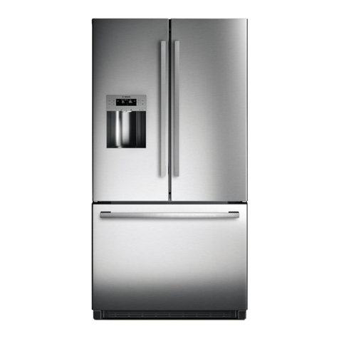
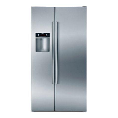
Bosch B22CS50SNW-01 Setup guide

R
R
RE
E
EP
P
PA
A
AR
R
RA
A
AT
T
TU
U
UR
R
RA
A
AN
N
NL
L
LE
E
EI
IIT
T
TU
U
UN
N
NG
G
G
General repair-instruction Cooling / Freezing
173_58300000002379_ara_en_j.doc – 29.04.14 Seite 1 von 41
1SAFETY.........................................................2
1.1 Safety instructions...............................................................2
1.2 Repair instructions ..............................................................2
2THEMES VON A – Z......................................3
2.1 Condensation tray flows over.............................................3
2.2 Check list for installation faults..........................................4
2.3 Colour changeover white ....................................................5
2.4 Detached metal strips from the front ................................. 5
2.5 Opening the refrigeration circuit ........................................ 6
2.6 Energy absorption ...............................................................6
2.7 Bottlenecks in the circuit (partial blockage)......................8
2.8 Humidity................................................................................8
2.9 Noises .................................................................................10
2.10 Noise measure from customer..........................................16
2.11 Odours ................................................................................17
2.12 Repairing the refrigeration circuit ....................................18
2.13 Refrigeration circuit leaking.............................................. 24
2.14 Refrigerant capacity specification.................................... 24
2.15 Refrigeration zones in the refrigerator compartment .....24
2.16 Small holes in the food compartment liner...................... 25
2.17 Cleaning and caring for stainless steel appliances........26
2.18 Temperature ....................................................................... 27
2.19 Filler neck on the compressor too short.......................... 32
2.20 Compressor Diagnostics...................................................33
2.21 Selection of the correct Lokring connection...................35
2.22 Lokring connection - Conditions of the tubes .................35
2.23 Leak in the foam .................................................................36
2.24 Removing adhesive residue ..............................................36
2.25 Cracks in the refrigerated food container.........................37
2.26 Ice and drinking water have bad taste and odour............38
2.27 Different compartments .....................................................40
3LAW ADVICES ............................................41

173_58300000002379_ara_en_j.doc – 29.04.14 Seite 2 von 41
1 SAFETY
1.1 Safety instructions
Danger!
►Repairs may be carried out only by customer service
engineers trained by the manufacturer!
►The user may be put at considerable risk and injured by
improper repairs!
►If the appliance is faulty, the housing or frame may be live!
►Do not touch components in the appliance. Even the modules
can be live!
►Before commencing repairs, ALWAYS disconnect the
appliance from the power supply!
►If tests have to be conducted while the appliance is live,
ALWAYS use a residual-current-operated circuit-breaker!
►The protective conductor connection must not exceed the
standardised values! This is essential for personal safety and
appliance function!
►When repairs are complete, conduct a test in accordance with
VDE 0701 or the corresponding national regulations as well as
a performance test!
►Conduct a leak and performance test on the refrigeration
circuit.
1.2 Repair instructions
Caution!
►Comply with ESD information!
►NEVER attempt repairs by randomly replacing components!
►Always proceed systematically and comply with the technical
documentation for the appliance!
►As a rule, printed-circuit boards are not repaired but are
completely replaced by original spare parts. Exceptions are
documented separately.
►When handling refrigerants, wear goggles and protective
gloves. If refrigerant splashes into eyes, rinse with plenty of
water.
►Pipe connections in refrigeration circuits must not be soldered.
Lokring connections must be used.

173_58300000002379_ara_en_j.doc – 29.04.14 Seite 3 von 41
2 THEMES VON A – Z
2.1 Condensation tray flows over
Condensation trays can overflow without visible mechanical failure
(loose or defect door gasket, etc.).
Solution:
In this case a self-adjusting heater has to be installed. This heater
assists the evaporation at a high water-level.
Spare part-No.: 00753407
The assembly has to be done according to the spare part information.
Please be sure that the heater is connected parallel to the power
supply.
Function:
If water completely surrounds the heater, the temperature and the
resistance decrease. Heater heats
If no water surrounds the heater, the temperature and the resistance
increase. heater stopps heating
Overview heater
Temperature in ºC
resistance in KΩ tolerance +/-30%
20 ºC
1,7 KΩ
30 ºC
2,3 KΩ
40 ºC
3,4 KΩ
50 ºC
6,2 KΩ
60 ºC
20,5 KΩ

173_58300000002379_ara_en_j.doc – 29.04.14 Seite 4 von 41
2.2 Check list for installation faults
Observe the ventilation dimensions in the installation
instructions. The air duct must not be obstructed. Non-
observance will impair the refrigeration circuit!
Observe the following points:
1. Maximum permitted weights of the furniture fronts:
Appliances with 2 cup hinges 9 kg
Appliances with 3 cup hinges 15 kg
Appliances with 4 cup hinges 18 kg
Appliances with flat hinges
The max. load for a flat hinge pair is 45 kg. This includes the
appliance door, the load of the door compartments and the
front panel.
Appliances with cushioned flat hinges
The max. load for a cushioned flat hinge pair is 62,5 kg. This
includes the appliance door, the load of the door
compartments and the front panel.
In this case, cushioned means that the hinge closes by itself
very slowly from an opening angle of 20°.
2. The transportation reinforcing strut in the rear area of the
kitchen furniture has not been removed. The rail prevents the
appliance from being inserted and the appliance protrudes
slightly.
3. The socket (surface type) is situated in the area of the motor
compartment. As a result, the refrigerator cannot be inserted
all the way either. The heat dissipated by the condenser and
the compressor may be impeded. Heat will build up and impair
the refrigeration circuit.
4. The screw in the upper installation strip brushes against the
cover panel on the built-under cupboard. The cause of this
fault are incorrect cup bores or an inaccurately dimensioned
mounting rail fitted to the front panel
5. The front panel is lopsided and brushes against the kitchen
furniture. Re-adjustment is possible only by removing the front
panel and correctly installing the mounting rail.
6. In isolated cases the cover base is missing from the built-in
cupboard. On the upperside of the appliance the cover plate
can be screwed only to the cupboard panel at the front. The
wood is tearing at this location, the screws slacken and the
appliance is no longer in the correct position.
7. The upper cupboard panel was not installed correctly and
therefore brushes against the front panel.
8. A blocked condensation outlet causes water to collect and run
out of the appliance at the front. The furniture base weakens
and the appliance moves up or down. The only remedial
action is to replace the furniture base.
9. If the appliance has been installed too deeply on the handle
side, the front panel strikes the carcass and the door does not
close. If this fault occurs, the depth has not been adjusted on
the appliance foot or has been adjusted too far at the rear.
We recommend a 50 cm wide spirit level and a try square as tools for
checking the correct installation location.
173_58300000002379_ara_en_j.doc – 29.04.14 Seite 5 von 41
2.3 Colour changeover white
The previous white (VZF 37351) has been changed over all product
ranges and all brands to a new, brighter white ( VZF0720 ).
The new white will be incorporated in the refrigerator/freezer area
without new factory part numbers, spare-parts numbers, VIBs or CSIs.
It will be permitted to mix the parts in the factory during a transition
phase: FD 8707 and FD 8708 in order to use up the old parts.
From FD 8709 only appliances with the new white will be
manufactured.
Exceptions to this rule are:
►FGK free-standing appliances KS/GS from 03/2007
►FGK tabletop appliances 60 cm 03/2007
Complaint:
When replacing a door, the customer could complain about the
different tones of white on appliances with several doors.
Example (old and new white)
If the customer complains contrary to expectations, proceed as des-
cribed in the TOM 58300000125889.
2.4 Detached metal strips from the front
The self-adhesive thin sheet-metal strips are becoming detached from
the upper or lower front strip. The thin sheet-metal strips hold the
magnetic door seals on the carcass of the appliance.
The repair kit, material no. 00290116, must be used for correct
attachment of a new thin sheet-metal strip.

173_58300000002379_ara_en_j.doc – 29.04.14 Seite 6 von 41
2.5 Opening the refrigeration circuit
Whenever the refrigeration circuit is opened, always
replace the dryer before evacuating and filling the
refrigeration circuit.
2.6 Energy absorption
2.6.1 Energy consumption
Information on the subject of energy consumption can also be
found in the “Energy consumption” brochure, material no.
584359.
The energy consumption values are indicated in 365 days in the
refrigerator pamphlets and on the energy label.
The consumption values are determined according to EN 153. The
specifications refer to 230 V, 50 Hz.
The conditions are:
►Ambient temperature 25 °C
►Compartment temperatures
Cold-storage compartment 8 °C to 12 °C
Refrigerator compartment 5 °C
”Cool-fresh” compartment: –2 °C to +3 °C
Freezer compartment –18 °C
►Door not opened
►Full load
The standard consumption value enables different appliances to be
compared.
2.6.2 Energy efficiency
The energy efficiency classes consist of energy consumption, usable
capacity and type of appliance.
The energy efficiency classes range
from A plus (very low)
to G (high).
2.6.3 Increased energy consumption
Several factors result in an increased energy consumption.
These factors are:
►High ambient temperatures
►Near heat sources (cooker, radiator, etc.)
►Exposure to sun
►High controller position
►Door opened frequently and for a long time (searching for food
due to untidiness results in the door being open for too long)
►Placing warm food in the appliance
►The evaporation and condensation of liquids (change of state)
cause a loss of refrigerating capacity
►A thick layer of ice on the evaporator

173_58300000002379_ara_en_j.doc – 29.04.14 Seite 7 von 41
2.6.4 Measuring the energy consumption
The energy consumption indicated in the brochures was determined in
the laboratory under standard conditions.
Measurements taken in the household deviate:
►The ambient temperature is not constant
(e.g. day and night)
►The appliance is used while the measurement is being taken
and therefore heat is introduced uncontrollably when the
appliance is loaded and unloaded and when the door is
opened.
►The appliance is exposed to a heat source
(e.g. if using an adjacent cooker)
►The measurement period is not usually selected for long
enough and the measuring instruments have not been
calibrated.
►The compartment temperatures cannot be set exactly for
some appliances.
►The compartment temperatures are subject to control cycles.
►If basic conditions vary (e.g. weekdays and workdays, change
in weather, etc.)
In order to take measurements which are approx. correct
(standard consumption value), the following basic conditions
must be observed:
►Ambient temperature approx. 25 °C when door is permanently
closed.
►Ambient temperature approx. 20 °C, in the household with the
usual loading and unloading of the appliance and opening of
the door.
►The following mean compartment temperatures
►Cold-storage compartment 8 °C to 12 °C
►Refrigerator compartment 5 °C
►”Cool-fresh” compartment: –2 °C to +3 °C
►Freezer compartment –18 °C
►Measure power consumption for 24 hours.
Special measuring instruments must be used which take the reactive
power into account (cos. ϕ).

173_58300000002379_ara_en_j.doc – 29.04.14 Seite 8 von 41
2.7 Bottlenecks in the circuit (partial blockage)
The capillary tube is the narrowest point in the refrigeration circuit.
A blockage caused by contaminants or a partial blockage is most
likely to occur in the capillary tube. The cross-section is narrowed by
refrigeration circuit contaminants which become deposited in the
capillary tube inlet. A bottle neck occurs which is similar to an injection
point. The narrowing may cause some of the refrigerant to be
released and evaporate. As a result, this bottleneck cools down. The
cooling process is transferred to the dryer and can therefore be
identified. In an extreme case even condensation may occur.
In principle, a bottleneck can occur on any soldered joint, e.g. even on
the solenoid valve.
2.8 Humidity
2.8.1 Increased humidity
Causes:
►Door seal leaking.
►Drainage channel or drainage hole for the condensation is
blocked.
►Long door opening times.
►Large quantities of moist food are stored unwrapped in the
appliance.
►Low ambient temperatures reduce the running time of the
compressor. In this case the humidity does not precipitate on
the evaporator but on the glass plates or on the food. (coldest
point)
►Bubbles (foaming fault caused by trapped air) in the partition
between the refrigerator and freezer sections.
►Door is not straight. (Curve)
►Front strip not completely sealed. Remedial action: Place
packing under door bearing washer.
►Seal not inserted all the way into the inner door.
►Uneven front strip.
►Large gap between side panel and front strip.
Remedial action (if there is no technical defect):
►Wipe rear panel with a detergent solution. As a result, the
water will be conveyed more quickly to the outside
(evaporation pan on the compressor).
►Advise customer, e.g. pack produce, avoid opening the door
for long periods, etc.

173_58300000002379_ara_en_j.doc – 29.04.14 Seite 9 von 41
►If possible, set a lower refrigerator compartment temperature
and increase the compressor running time.
2.8.2 Humidity on the side panel
Cause of fault:
If the air humidity is above 80 %, condensation may occur on the side
panel.
Condensation may occur especially in the case of so-called side-by-
side appliances (refrigerator and freezer are placed next to each
other) due to the lack of ventilation between the side panels.
Rectifying the fault:
Use repair kit, material no. 00435234 (see drawing)
The repair kit can also be used for built-in appliances.

173_58300000002379_ara_en_j.doc – 29.04.14 Seite 10 von 41
2.9 Noises
2.9.1 Normal noises
►Compressor noise
The droning noise is generated by the compressor. It may briefly
become slightly louder when the compressor switches on. When the
compressor switches off, a rattling noise may be heard.
►Flowing noises
The bubbling or gurling noise is generated by the refrigerant as it
flows through the tubes.
►Switching noises
The clicking noise is caused by the temperature controller or
a solenoid valve.
►Air-flow noises
If the appliance features an internal fan (No Frost), the air flow inside
the appliance may generate a rushing noise.

173_58300000002379_ara_en_j.doc – 29.04.14 Seite 11 von 41
2.9.2 Eliminating causes of noise
►Appliance is not level
Level the appliance with the aid of a spirit level. Use the height-
adjustable feet or place packing underneath them.
►The appliance is not free-standing
Move the appliance away from furniture or appliances.
►Built-in parts are loose or sticking
Check the removable parts and, if required, re-insert.
►Bottles or receptacles are touching each other
Move bottles or receptacles away from each other.

173_58300000002379_ara_en_j.doc – 29.04.14 Seite 12 von 41
►Junction of the throttle/suction tube (forked tube)
vibrating
To prevent vibration noises, the junction of the throttle / suction tube
should be jacketed with an absorption material, material no.
00153737.
On the compressor:
On the freezer compartment evaporator:

173_58300000002379_ara_en_j.doc – 29.04.14 Seite 13 von 41
►Flowing noises on the evaporator
Loud flowing noises are generated by residual air in the refrigeration
circuit. The circuit must not be rinsed while there are flowing noises.
Type of noises:
Rustling, splashing, gurgling, bubbling.
Remedial action:
Carefully evacuate refrigeration circuit on both sides for at least
15 minutes. Then fill the appliance according to the instructions.
If the appliance is not filled according to the instructions, air may get
into the refrigeration circuit.
►Injection noises on the evaporator
The refrigerant is injected at high speed into the evaporator at the end
of the throttle tube (injection point). If the end of the throttle tube is
bent, increased injection noises will occur.
Type of noises:
Fizzing, hissing, whistling, trumpeting, scratching.
Remedial action:
There is no remedial action for refrigerator compartment aluminium
evaporators. The throttel tube is not accessible at the injection point.
If the freezer compartment features a wire tube evaporator, check that
the throttle tube runs straight in the injection area (in front of the
soldered joint). If required, carefully straighten the tube (risk of
fracture)! Jacket the injection point with absorption material, material
no. 00153737.
2.9.3 History of noise generation
The type of noises has changed in modern refrigerators/freezers.
Modern appliances are usually quieter than old refrigerators/freezers.
However, the noises have changed on account of energy-saving
compressors, environmentally friendly refrigerants and internally
foamed evaporators, ranging from low to high-frequency sounds.
High sounds are usually felt to be more offending than low sounds
(comparison: mosquito – bee)
2.9.4 Noise diagnosis
If a complaint is made, assess the volume of the noise when the
appliance door is closed.
In the case of a customer complaint about multi-zone appliances,
check which zone is generating the noise. Only then decide how to
proceed further.
The two following flow diagrams will help you decide how to proceed
and how to test for noises.

173_58300000002379_ara_en_j.doc – 29.04.14 Seite 14 von 41
Customer information:
- Explain operating noise.
Use additional information: "NOISES"
-Argumentation for comparison of old and
new appliances:
•Foamed evaporators
•Energy-saving compressor
•Ecological refrigerant fluid
Consult regional management a./o. CS-Trainer
Rebuy appliance
Level the appliance. Use the height-adjustable feet
or place packing underneath them. If possible: Move
appliance away from wall or close-by furniture
Fix removable parts (storage shelves, frames…)
Bend pipes until they can swing freely (if
necessary: insert absorption- or distance-parts)
Is customer still dissatisfied?
Is customer dissatisfied?
Is the appliance too noisy?
(subjective impression)
Noise testing
Is customer complaint
justified?
Simple, mechanical noise
("rattling")?
Does the appliance stand
on level and stable?
Are removable parts fixed
in the appliance?
Are the pipes in
condenser area laid
contact-free?
Is customer dissatisfied?
Is customer complaint still
justified?
Exchange appliance
End
1
2
no
no
no
no
yes
no
Sheet 2
Sheet 2
yes
yes
yes
End
no
no
no
no
yes
yes
yes
yes
yes
no

173_58300000002379_ara_en_j.doc – 29.04.14 Seite 15 von 41
Compressor-, circuit-noise
(vibrating, whistling, bubbling,
gargling, humming, pulsating)?
Absorption material on:
•Forked tube?
•GS evaporator
Attach “Thermomatte”
between compressor and
mounting plate
Is the fan fixed,
centrical?
Does the compressor transmit
noises on mounting plate?
2
Is internal or external
fan available?
Fan noise,
screaming,
scratching noise?
Fan okay?
Is the internal fan
ice-free?
Fix fan centrical /
Replace fan
Eliminate causation
Replace fan
Compressor okay?
Replace
compressor
Laying of capillary tube okay?
(particularly before FD 7210)
- Straighten capillary?
- Is laying between GS- and
KS-part kink-free?
Pulsating noises?
Evacuate refrigeration circuit carefully and fill
the appliance (don’t jet it before)
Attach absorption material
Fix capillary tube with cable
tie
1
yes
yes
yes
yes
yes
yes
yes
yes
yes
no
no
no
no
no
no
yes
yes
no
no
no
no
no

173_58300000002379_ara_en_j.doc – 29.04.14 Seite 16 von 41
2.10 Noise measure from customer
Hint
The information about the noise level in the product info helps the
customer to compare cooling appliances themselves. Like the
Information about the fuel consumption on Cars.
The noise level according to DIN (Norm IEC 60704) is measured and
confirmed in laboratory.
To measure again in household with noise-meter or programs /
software like app´s for smartphone
or similar is not possible.
Background
More frequently the customer service faces complaints from the
customer measuring noise level of appliances by using a smartphone
application. Often high differences between the measured numbers
and the labeled numbers are observed. Below arguments are given to
explain such differences.
Explanation
For the determination of noise the declaration value manufacturers
have to follow exactly described rules. They are defined in the
international standard IEC 60704. The procedures and boundary
conditions described in this standard cannot be fulfilled in a regular
household environment and by technical equipment of a smartphone.
Out of that errors and deviations must be expected when doing a
noise measurement with a smartphone in a living environment. Main
arguments are:
1. The manufacturer’s declared noise level is a sound power level.
Smartphone apps only measure sound pressure level. Both may not
be mixed up.
2. The used equipment – a smartphone – does not have the required
precision.
3. The application does not apply all needed post processing
procedures as required in the standard IEC 60704. Especially the
required time average for a clearly specified time frame is not done.
4. It must be expected that the applied algorithms in the app are faulty.
Usually such apps are not certified or created by hobby programmers
who do not know about all required specification. Thus errors must
be expected.
5. Kitchens, living rooms or apartments in general do not fulfill the
requirements for standardized test room as described in IEC 60704.
By not fulfilling these requirements measurements at home cannot
give the right and comparable measurement result.
To 1.)
A smartphone-app only can measure the sound pressure at the
position in space where the smartphone has been placed. By varying
the position the sound pressure level changes. The customer can
check it easily by repeating measurements at different positions at
home.
But the stated noise level on the label is a sound power level. This
sound power level is independent from the microphone position. It is a
method to compare product in an equal way. But it needs well defined
test procedures, high-precision test equipment and a standardized
test environment. The sound power is a number describing the totally
radiated sound of an object, e.g. home appliances. It characterizes an
appliance allowing a comparison of appliances with each other. This is
not possible to be realized at home!
To 2.)
A smartphone does not use a precise microphone and the electronics
causes a high background noise versus the measurement signal. Also
the sensitivity of the smartphone microphone is not good in every
relevant frequency range. These negative properties reduce the
accuracy of test result. Usually these microphones also have different
sensitivity depending from the direction the noise is coming from.
Therefore depending from the angle the smartphone is hold the test
result will vary. Again a deviation from the real noise level must be
expected.
To guarantee the accuracy of the test results microphones have to be
calibrated on a regular basis. For smartphones this is not possible.
Thus the accuracy is low.

173_58300000002379_ara_en_j.doc – 29.04.14 Seite 17 von 41
To 3.)
For the calculation of a refrigerator‘s declaration value according to
IEC 60704 at least 3 or up to 6 compressor runtimes have to be
recorded and time-averaged in the correct way. Smartphone apps
cannot do such post processing. Usually only real time values are
given or short time averages are calculated. But averaging of several
compressor runtimes requires measurement of up to several hours. In
this time no disturbing noise may occur in the test environment. This is
hardly to fulfill at home.
To 4.)
Often applications are not created by professional programmers by
the help of acoustic experts. Thus it must be expected that the
correctness of such an app is not certified and approved. Therefore it
is not guaranteed that the right algorithms have been applied to give
the correct sound pressure level. Most likely the results are not
conform to international standards and thus cannot be compared with
the manufactures declaration value.
(At trials by the acoustic experts of B/S/H differences of up to 40dB
between the different apps and smartphones have been observed.
This shows how unreliable the given results can be.)
To 5.)
Regular apartments do not give an appropriate test environment for
comparable noise tests to verify the declared noise value. Apartments
or houses are very different to each other regarding dimensions,
surfaces and furniture. This means many individual parameter have a
significant influence on the acoustical behavior and thus on the test
results. This is another reason why a customer cannot verify a noise
declaration value at home. It needs specially designed noise
chambers meeting the requirements of international standards.
2.11 Odours
Our appliances are manufactured from plastics which conform to the
Lebensmittel-Bedarfs-Gegenstands-Gesetz (Ordinance on Food
Products and Articles for Domestic Use) (suitable for food, non-toxic,
etc.).
However, when an appliance is delivered (in a warm condition), it has
a typically plastic odour which disappears when the appliance is
switched on. If the complaint does not occur as soon as the appliance
has been switched on, the offensive odour and flavour cannot be
caused by the appliance.
2.11.1 Complaints about odours
Appliance switched off and the appliance door closed
If the appliance is switched off for a prolonged period (e.g. during the
annual vacation). The door kept closed and not or only partially
cleaned, a musty odour develops in the appliance.
Information in the operating instructions:
Switch off, disconnect the appliance
►If the appliance is not to be used for a prolonged period:
Switch off appliance, defrost freezer compartment (if
featured), clean entire appliance, keep all doors open.
Remedial action:
Clean appliance thoroughly and ventilate. When the appliance is
switched on, the odour can no longer be detected in the cold
appliance.
Produce stored open (unwrapped) in the appliance
Especially critical is the storage of citrus fruits. Citrus fruits which have
been treated with chemicals may produce a “chemical” odour inside

173_58300000002379_ara_en_j.doc – 29.04.14 Seite 18 von 41
the appliance. This “chemical” odour sticks to plastic and, in the most
unfavourable case, may alter the flavour of other non-packed food.
Information in the operating instructions:
If possible, pack food or cover well before placing in the appliance.
Remedial action:
Clean appliance thoroughly (vinegar water) and ventilate for
a prolonged period. When the appliance is switched on again, the
odour will diminish. If odours are stubborn, clean the appliance
several times. Then clean the appliance monthly with a detergent
solution, as recommended in the operating instructions.
Produce in the appliance has gone off
The odour from food which has gone off may stick to the plastic of the
inner container. The refrigerator compartment then gives off odours
over a prolonged period. In the most unfavourable case the flavour of
other non-packed food may be altered.
Information in the operating instructions:
If possible, pack food or cover well before placing in the appliance.
Remedial action:
Clean appliance thoroughly (vinegar water) and ventilate for
a prolonged period. When the appliance is switched on again, the
odour will diminish. If odours are stubborn, clean the appliance
several times. Then clean the appliance monthly with a detergent
solution, as recommended in the operating instructions.
2.12 Repairing the refrigeration circuit
2.12.1 Safety instructions
When handling refrigerants, specific safety measures must be
observed:
Refrigerants evaporate at room temperature. If liquid refrigerant
comes into contact with your skin, the refrigerant evaporates
immediately and, as a result, removes heat from the environment.
This may result in injuries with the same symptoms as burns.
Therefore, goggles and protective gloves must be worn. If refrigerant
splashes into eyes, rinse with plenty of water.
Wear goggles and protective gloves!
No naked flames and no smoking when working on refrigeration
circuits.
There is a risk of fire and explosion with R600a.
If R134a comes into contact with a naked flame, the refrigerant
decomposes Toxic substances are emitted.
No naked flames and no smoking!

173_58300000002379_ara_en_j.doc – 29.04.14 Seite 19 von 41
2.12.2 R 600a
2.12.2.1 Take precautions when repairing the the refrigerant circuit
The hydrocarbon R 600A is highly flammable, however only in
combination with air, and explosive at a specific mixing ratio.
This flammable mixture cannot occur with our usual quantities unless
there is an accumulation of extremely unfortunate circumstances.
Nevertheless the following safety measures must be taken when
handling R 600A:
►provide good ventilation in the appropriate rooms (open
windows and doors)
►Keep ignition sources away
►No smoking!
►No naked flames (e.g. gas cooker, candle)
Therefore, never work on the R 600A refrigerant circuit
with a flame and resistance soldering equipment!
2.12.2.2 Filling accuracy
To keep refrigerant losses as low as possible (even a 2 g loss will
significantly impair the function of the refrigerator), the filling hoses
must be as short as possible. This ensures that gas volume remaining
in the test equipment is low and that the appliance is in perfect
working order after the repair.
2.12.2.3 Disposal of compressor oil
The refrigerant dissolved in the oil of the R 600A compressors cannot
be completely removed at a justifiable cost. R 600A compressors
should therefore be completely and hermetically sealed prior to
disposal.
If the compressor oil has to be disposed of separately, comply
with the following:
►Before removing the oil, evacuate the compressor for at least
15 minutes. In doing so, provide good ventilation or convey
the exhaust gases of the vacuum pump outside.
►Even following evacuation, R 600A remains dissolved in the
compressor oil, approx. 1 g per 200 ml. The compressor oil
must therefore be disposed of in A1-suitable containers. To
minimise the residual risk, fairly small containers not larger
than 1 litre should be used, as 1 litre of oil contains only
approx. 5 g of R 600A. 20 litres of oil contain approx. 100 g of
dissolved R 600A.
►The oil recipient must be informed that the oil contains
dissolved R 600A refrigerant and that this refrigertant is
flammable and is explosive in air within the limit 1.3 to
8.5 vol. %.

173_58300000002379_ara_en_j.doc – 29.04.14 Seite 20 von 41
2.12.2.4 Repairs to the R 600A refrigerant circuit
Draining the refrigerant
The refrigerant circuit must be punctured on both sides in order to
bypass blockages on the pressure side.
The free gas component of the excess pressure (at room temperature
for KTR1570-Öko, with a total filling amount of 22 g, this is approx.
4–5 g, as approx. 4 g remain in the refrigerant circuit and approx. 14 g
in the compressor oil) then blows off. The remaining refrigerant filling
amount remains dissolved in the oil.
Replacing components
Disconnect the dryer and if required the compressor from the
refrigerant circuit with a pipe cutter.
If the compressor is removed, its connections must be
hermetically sealed immediately with Lokring blank
plugs to prevent the R 600A dissolved in the
compressor oil from evaporating and flowing out of the
connectors during transportation.
Filling amount calibration
If the balance is not operated for 2 minutes, it switches
off automatically.
The filling amount of the cartridge cannot be taken for
granted as refrigerant may escape via the valve during
the storage period.
Working steps: Example:
►Check weighing accuracy with standard weight and, if
required, re-adjust the balance.
►Weigh extraction valve (subtract) – 65.4 g
►Empty weight of the refrigerant cartridge, e.g. 29.5 g (subtract)
– 29.5 g
►Screw extraction valve onto the refrigerant cartridge.
►Weigh refrigerant cartridge with screwed-on extraction valve
and add the weight (this takes into consideration the
refrigerant lost when extraction valve screwed on and during
storage). +150.2 g
►Result: Nett filling amount of the refrigerant cartridge 55.3 g
►Determine excess refrigerant amount (drainage amount)
with compressor change:
►Nett filling amount of the refrigerant cartridge 55.3 g
Subtract appliance filling amount (rating plate) – 23.0 g
►Result: Drainage amount, with compressor change 32.3 g
With a compressor change, 32.3 g R 600A are to be drained
from the cartridge.
without compressor change:
The refrigerant R 600A dissolves very easily in the compressor oil and
cannot be completely removed even during the 10-minute evacuation.
If the compressor is not replaced, the filling amount must be reduced
by 1 g, i.e. the drainage amount must be increased by 1 g.
►Drainage amount, with compressor change 32.3 g
►Filling amount difference, 1 g (add) + 1.0 g
►Result: Drainage amount, without compressor change 33.3 g
►Without a compressor change, 33.3 g R 600A are to be
drained from the cartridge.
►Drain the refrigerant
Table of contents
Other Bosch Refrigerator manuals

Bosch
Bosch KIV86 Series User manual

Bosch
Bosch KSR38N11GB User manual

Bosch
Bosch KUR15ADF0 Specification sheet

Bosch
Bosch KDN series User manual

Bosch
Bosch KFN96VPEAA Specification sheet

Bosch
Bosch KUR SERIES User manual

Bosch
Bosch GSN series User manual

Bosch
Bosch B22CS Series User manual

Bosch
Bosch KDN series User manual

Bosch
Bosch Refrigeration Manual

Bosch
Bosch KDN series User manual

Bosch
Bosch KGN Series Specification sheet

Bosch
Bosch RY492705 User manual

Bosch
Bosch KG36NXI40 User manual

Bosch
Bosch CTC35 Series Specification sheet

Bosch
Bosch KGN36VL21 User manual

Bosch
Bosch B26FT series User manual

Bosch
Bosch KFN96VPEAG User manual

Bosch
Bosch KIF81H Series User manual

Bosch
Bosch B1.. CB SERIES User manual