System Description
3
System Overview with Functional Variants
The SE 220 LSNi SmartKey arming device is a system solution for arming intrusion systems. The
individual components of the system can be put together as required for the intended usage. Op-
eration types with or without the SPE blocking element are possible. Control authorizations for
arming/disarming are defined during control panel programming. The system is programmed us-
ing an appropriate programming program. All the information and explanations you need to pro-
gram the system can be found in the online help, i.e. directly on the screen.
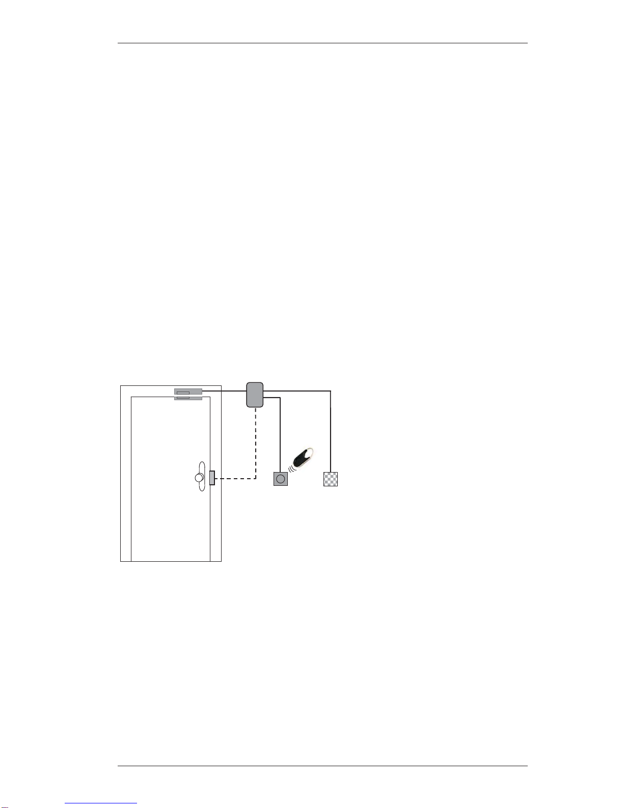
SPE blocking element
The SPE blocking element is an additional
lock for the door and is meant to prevent
unauthorized entry to the armed area. The
SPE blocking element is always installed in
conjunction with a kit in the secure area to
enable it to accommodate different doors.
The image shows a door-mounted installa-
tion; for other variants, please see installing
the SPE blocking element. A conventional
magnetic contact can be used with the
door-mounted installation kit. Operation ty-
pes with and without blocking elements are
possible.
SE 220 LSNi control unit
The control unit processes the status reports of
all components in the system, communicates
these reports to the intrusion alarm system and
controls the SPE blocking element. The control
unit is installed in the secure area.
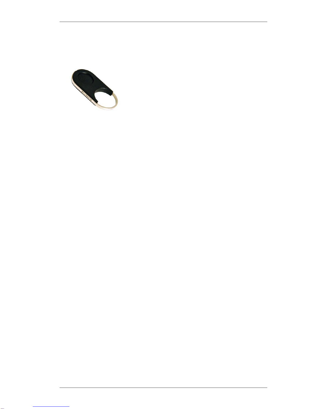
Reader
The system is armed and disarmed
by holding an electronic key up to
the reader. The LED and buzzer
provide information about the status
of the system as well as operation.
The reader can be surface mounted
or recessed mounted (outside the
secure area).
Code keypad
There are two types of code keypads
xSmartKey code keypad
xLockable code keypad
The code keypad, used in conjunc-
tion with the reader, allows arming
and disarming of the intrusion alarm
system only after the correct combi-
nation of numbers has been entered
on the code keypad.
If someone is forced to disarm the in-
trusion alarm system under duress,
a silent alarm (hold-up alarm)
can be set off remotely via the code
keypad.
The code keypad can be surface
mounted or recessed mounted (out-
side the secure area).
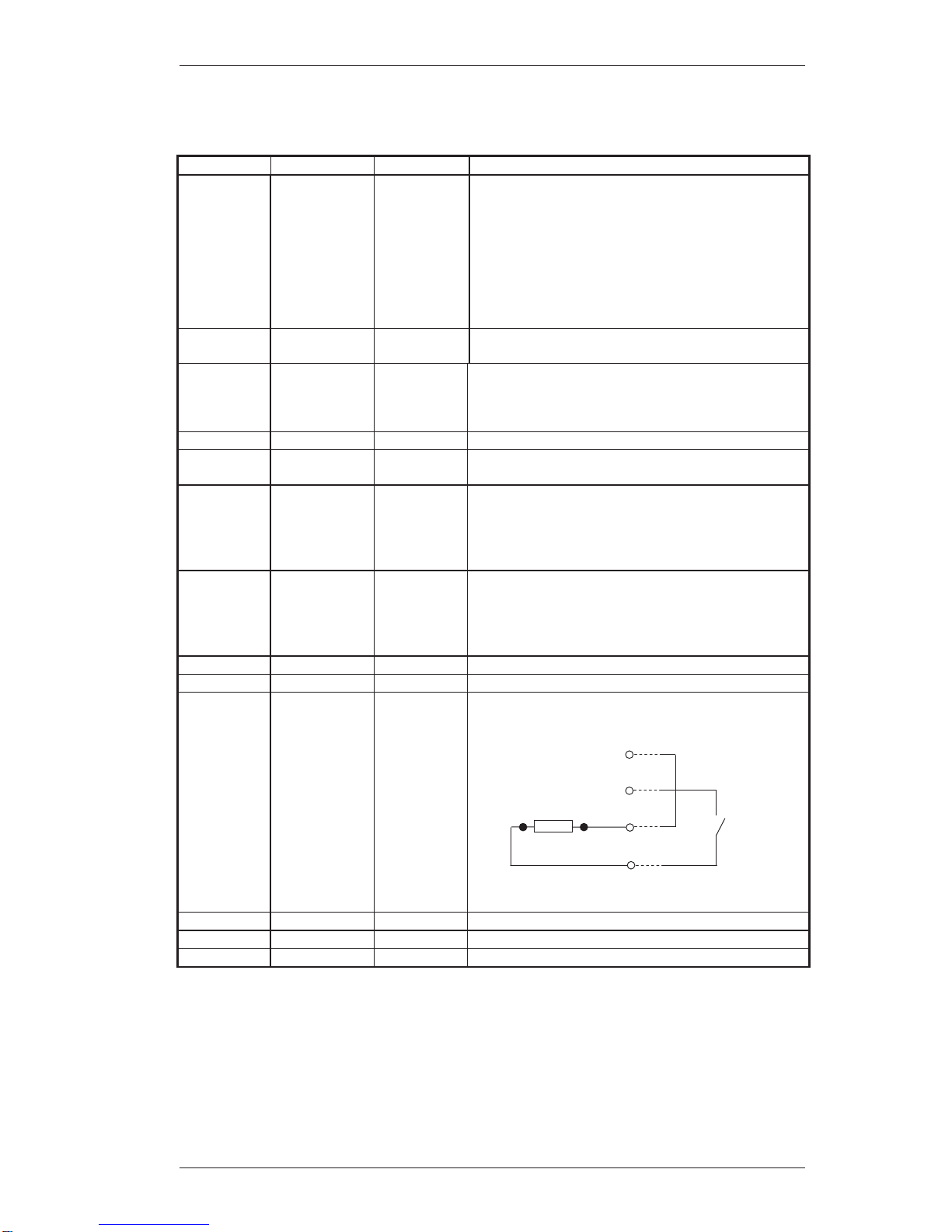
Bolt contact