3
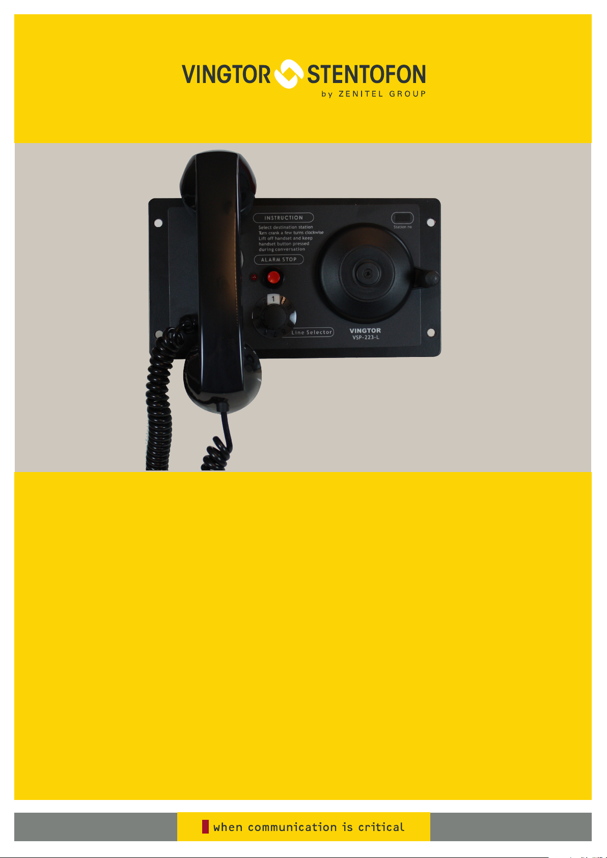
VSP 12-Way Batteryless Telephone System
Technical Manual
A100K10873
Contents
1 General Description........................................................................................................4
1.1 System ...................................................................................................................4
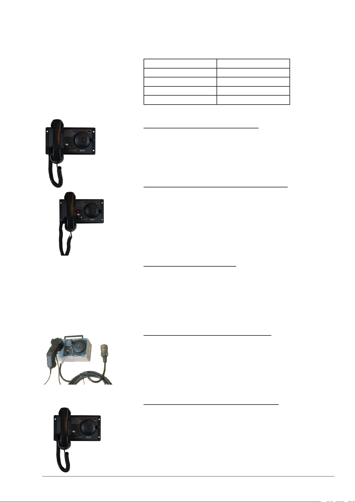
1.2 Station Types..........................................................................................................5
2 Functional Description...................................................................................................6
2.1 Power .....................................................................................................................6
2.2 Calling ....................................................................................................................6
2.3 Amplier .................................................................................................................7
2.4 Call Signal ..............................................................................................................7
2.4.1 Stations for Use in Safe Areas .........................................................................7
2.4.2 Stations for Use in Hazardous Areas ...............................................................7
2.5 Handset ..................................................................................................................7
3 Installation.......................................................................................................................8
3.1 Connection .............................................................................................................8
3.2 Cabling ...................................................................................................................8
3.3 Compass Safety ...................................................................................................10
3.4 Setting Extension Number....................................................................................10
4 Operation....................................................................................................................... 11
5 Troubleshooting............................................................................................................12
5.1 Conversation Lines...............................................................................................12
5.2 Call Tone...............................................................................................................12
6 Specications................................................................................................................13
6.1 Electrical Specications........................................................................................13
6.2 Certicates ...........................................................................................................13
7 DIP Switch Settings for Extension Numbers..............................................................15
8 Station & Mounting Dimensions..................................................................................16
8.1 VSP-122 ...............................................................................................................16
8.2 VSP-122P.............................................................................................................17
8.3 VSP-211-L ............................................................................................................18
8.4 VSP-213-L............................................................................................................18
8.5 VSP-223-L............................................................................................................19
Figures
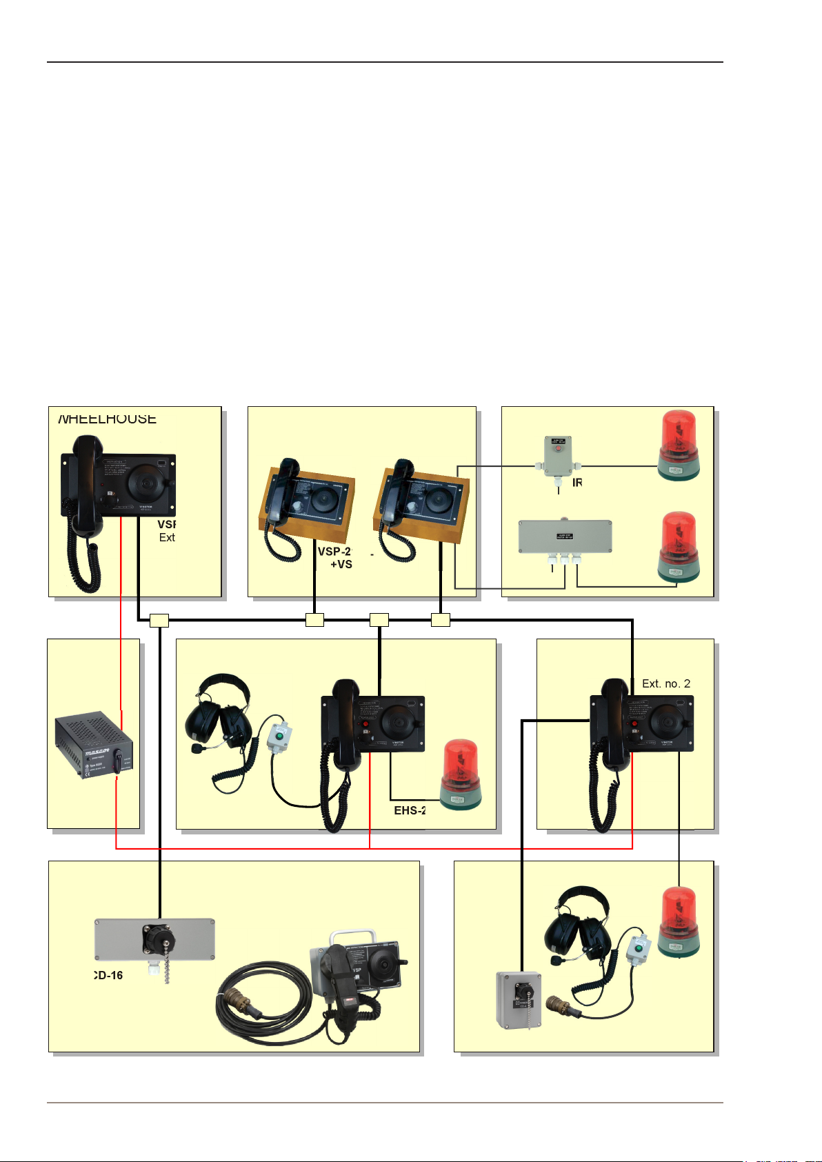
Figure 1: System Conguration Example.................................................................................................................... 4
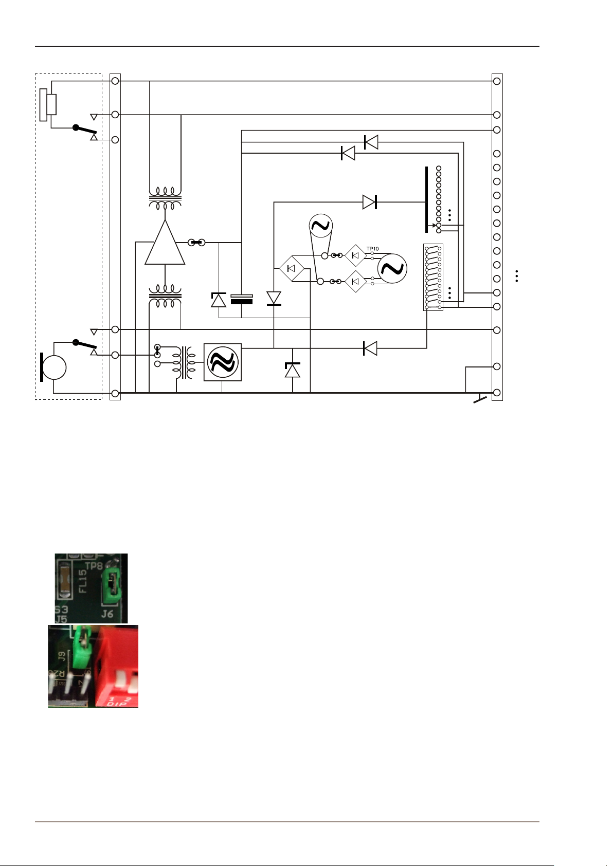
Figure 2: Main station VSP-211-L principle diagram................................................................................................... 6
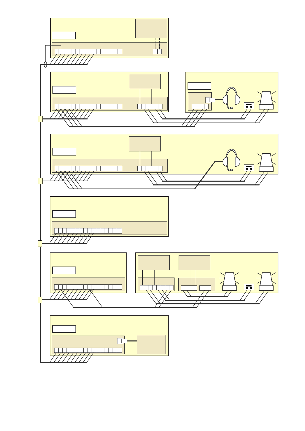
Figure 3: Cabling diagram based on system conguration example .......................................................................... 9
Figure 4: DIP switch setting for extension no. 2........................................................................................................ 10
Figure 5: Extension number label ............................................................................................................................. 10