Boschmann CT1644 User manual

Product code CT1644 and CT1645
230mm heavy duty Angle grinder
Instruction Manual
Please keep this instruction manual for future reference

Table of Contents
Section Page
Declaration of conformity 1
Product specification 2
Power tool safety instructions 3 - 4 - 5
Know your angle grinder 5
Controls and operation 6
Fitting a cutting, and grinding disc 7 - 8
General information 8
Carton contents 9
Symbols 10
Parts Diagram 11
Parts List 12
Electrical Information 13
DECLARATION OF CONFORMITY
We the importer.
CANNON TOOLS LTD
Add: 20 station road, Rowley Regis, west midlands,B65 OJU.U.K.
DECLARE THAT THE PRODUCT 1644 and 1645 Angle Grinder
ARE IN CONFORMITY WITH THE FOLLOWING DIRECTIVES TO THE SPECIFICATION
UNDER WHICH CONFORMITY IS DECLARED.
THE LOW VOLTAGE DIRECTIVE (DIRECTIVE 73/23/EEC)
THE EMC DIRECTIVE (DIRECTIVE 89/336/EEC)
THE MACHINERY DIRECTIVE (DIRECTIVE 89/392/EEC)
DIRECTIVE ON ELECTROMAGNETIC COMPATIBILITY 93/68/EEC COUNCIL DIRECTIVE 98/37/EC
(CE MARKING DIRECTIVE)
CANNON TOOLS LTD
sign
Page 1
Accessories.
1 Pin wrench
1 pair carbon brushes
1 Hex key

CAUTION.
Carefully read through this entire instruction manual before using your new power tool. Take
special care to heed the Cautions and Warnings
TECHNICAL DATA
We have made every effort to ensure accuracy of information in this manual at time of going to
print.
Specification
Angle grinder 9”230mm Product CT1644 Product CT1645
Voltage 230/240v-50Hz 110/115v-60Hz
Input power 2000w 2000w
No load speed 6000rpm 6000rpm
Disc diameter 9”/∅230mm 9”/∅230mm
Disc bore diameter ∅22.2 ∅22.2
Spindlethread M14 M14
Protection class class II class II
Weight 3.2kg 3.2kg
This tool is double insulated. There are two independent barriers of insulation to protect you from the
possibility of electric shock.
NOISE AND VIBRATION DATA
Typical weighted Vibration 2.5m/s² 2.5m/s²
A weighted sound pressure 98.5dB(A) 98.5dB(A)
A weighted Sound power 111.5dB(A) 111.5dB(A)
Sound pressure is over 85dB(A) 85dB(A)
The sound intensity level for the operator may exceed 85dB(A) and sound protection measures are
necessary.
You must always wear the following if operating this power tool.
Wear goggles.
Wear ear defenders.
Wear a breathing mask.
Wear safety gloves
Wear safety shoes
Page 2

SAFETY INSTRUCTIONS
To use this tool properly, you must observe the safety regulations, the assembly instructions and the operating
instructions to be found in this manual. All persons who use and service the machine have to be acquainted with
this manual and must be informed about any potential hazards.
Children and infirm people must not use this tool. Children should be supervised at all times if they are in the area
in which the tool is being used. It is also imperative that you observe the accident prevention regulations in force in
your area. The same applies for general rules of occupational health and safety.
The manufacturer shall not be liable for any changes made to the tool nor damage resulting from such changes.
Even when the tool is used as prescribed it is not possible to eliminate all residual risk factors. The following
hazards may arise in connection with the tools construction and design:
Contact with disc
Kickback of work piece and parts of work piece.
Disc fracture.
Catapulting of disc pieces.
Damage to hearing if effective ear defenders are not worn.
Damage to the lungs if an effective dust mask is not worn.
Do not use discs that are damaged or cracked.
Always remove the plug from the mains socket before making any adjustments or maintenance, including
changing disc.
WARNING
When using electric power tools, basic safety precautions including the following, should always be followed to
reduce the risk of fire electric shock and personal injury. Also please read and heed the advice given in the
additional important safety instructions.
READ ALL THESE INSTRUCTIONS BEFORE OPERATING THIS PRODUCT AND SAVE THESE
INSTRUCTIONS.
1. Keep the work area clean and tidy. Cluttered work areas and benches invite accidents and invite injury.
2. Consider work area environment. Do not expose power tools to rain. Do not use power tools in damp
or wet locations. Keep the work area well lit. Do not use power tools where there is risk to cause fire or
explosion. Do not use power tools in the presence of flammable liquids or gases.
3. Guard against electric shock. Avoid body contact with earthed or grounded surfaces (e.g. pipes,
radiators, ranges, refrigerators).
4. Keep children and visitors away from the work area. All visitors and onlookers, especially children
and infirm persons should be kept well away from where you are working. Do not let others in the
vicinity make contact with the tool or extension cord.
5. Store idle tools. When not in use, tools should be stored in a dry, high or locked up place out of reach of
children.
6. Do not force the tool. The tool will do the job better and safer at the rate for which it was designed.
7. Use the right tool. Do not force small tools or attachments to do the job best handled by a heavier duty
tool. Do not use tools for purposes not intended; do not use circular saws to cut tree limbs or logs.
8. Dress correctly. Do not wear loose clothing or jewellery; they can be caught in moving parts. Rubber
gloves and non-slip footwear are recommended when working outdoors. Wear a protective hair covering
to contain long hair.
9. Use safety accessories. Safety glasses and ear defenders should always be worn. A face or dust mask is
also required.
10. Connect dust extraction equipment. If devices are provided for the connection of dust extraction and
collection facilities, ensure that these are connected and properly used.
11. Do not abuse the power cord. Never carry the tool by the cord or yank it to disconnect it from the
socket. Keep the cord away from heat, oil and sharp edges.
12. Secure the work piece. Use clamps or a vice to hold the work piece. It is safer than using your hand and
it frees both hands to operate the tool.
13. Do not overreach. Keep proper footing and balance at all times.
14. Maintain and Look after your tools with care. Keep cutting tools clean and sharp for better and safer
performance. Follow the instructions for lubrication and accessory changes. Inspect tool cords
periodically and if damaged have it repaired by an authorized service facility. Inspect extension cords
periodically and replace, if damaged. Keep tool handles dry, clean and free from oil and grease.
15. Disconnect tools. Switch off the power. Disconnect the plug from the power point before servicing and
when changing accessories such as blades, bits and cutters, and when the tool is not in use.
16. Remove adjusting keys and wrenches. Form the habit of checking to see that the keys and adjusting
wrenches are removed from the tool before switching the tool on.
17. Avoid unintentional starting. Ensure that the switch is in the OFF position before plugging the tool to
the power supply. Do not carry a plugged in tool with your finger on the switch.
Page 3
18. Use outdoor rated extension cords. When a tool is used outdoors, use only extension cords that are
intended for outdoor use and are so marked.

19. Stay alert. Watch what you are doing. Use common sense. Do not operate a power tool when you are
tired.
20. Check for damaged parts. Before using a tool, check that there are no damaged parts, if a part is
slightly damaged carefully determine if it will operate properly and perform its intended function other
wise replace. Check for alignment of moving parts binding of moving parts, breakage of parts, free
running of moving parts, proper mounting and any other conditions that may affect the operation of the
tool. A guard or other parts that are damaged should be properly repaired or replaced by an authorised
service centre, unless otherwise indicated in this instruction manual. Defective switches must be replaced
by authorised service facility. Do not use the tool if the switch does not turn the tool on and off correctly.
21. Warning. The use of any accessory or attachment, other than those recommended in this instruction
manual, may present a risk of personal injury.
22. Have your tool repaired by a qualified person. This electric tool is in accordance with the relevant
safety requirements. Repairs should only be carried out by qualified persons using original spare parts;
otherwise this may result in considerable danger to the user.
23. Do not let a tool run unattended. Always wait until your power tool has come to a complete stop
before leaving it. Then turn off at mains and remove the plug from the power outlet.
WARNING
The use of an accessory or attachment, other than those recommended in this instruction manual may present a risk
of personal injury
The tool must be used only for its prescribed purpose any use other than those mentioned in this manual will be
considered a case of misuse. The user and not the manufacture shall be liable for any damage or injury resulting
from such cases of misuse.
ADDITION SAFETY RULES FOR ANGLE GRINDER
•Fully unwind cable drum extensions to avoid potential overheating.
•When an extension cable is required, you must ensure that it has the right ampere rating for your
Power tool and is in safe electrical condition.
•Ensure your mains supply voltage is the same as your tool rating plate voltage.
•Always switch off before you put the angle grinder down.
•Keep the area free of tripping hazards.
•Do not let anyone under the age of 18 years operate this tool.
•Rags, cloths, cord, string and the like should never be left around the work area.
•If you are interrupted when operating the tool, complete the process and switch off before looking up.
•Periodically check that all the nuts, bolts and other fixings are properly tightened.
•Abrasive wheels shall be stored and handled with care in accordance with manufactures instructions.
•Do not store materials or equipment above a machine in such a way that they could fall into it.
•Do not use discs having a maximum permissible speed below the tool rated marked RPM.
•Inspect the grinding wheel before use, do not use chipped, cracked or otherwise defective products. Check the
disc before mounting it into the angle grinder. Check by striking it with a wooden handle whilst balancing the
disc on your finger. Listen to the sound it makes if it rings it is ok if it sounds dull it may be cracked and needs
to be replaced.
•Ensure that mounted wheels and points are fitted in accordance with the manufacturers instructions.
•When the disc is installed, run it for at least a minute to ensure that it does not have a fault. It is
always advisable to stay out of the line of the disc when testing or in general use.
•Do not use a disc marked with a lower RPM than that of the no load speed shown on the rating plate.
•Use discs only of the prescribed diameter.
•Never try to operate the angle grinder without the guard in place .
•Do not use separate reducing bushings or adaptors to adapt large hole abrasive wheels.
•For tools intended to be fitted with threaded hole wheel, ensure that the thread in the wheel is long enough to
accept the spindle length.
•Do not use cutting off wheel for side grinding.
•Ensure that sparks resulting from use do not create a hazard e.g. do not hit persons or ignite flammable
substances.
•Ensure that ventilation openings are kept clear when working in dusty conditions. If it should become
necessary to clear dust, first disconnect the tool from the mains supply (use non metallic objects) and avoid
damaging internal parts.
•If the supply cord is damaged, it must be replaced by the manufacturer or its service agent or a similarly
qualified person in order to avoid hazard.
Page4

•Do not secure the angle grinder in a vice or work bench and use it as a static grinder. It can lead to serious injury.
•Never apply excessive pressure to the disc it might shatter causing personal injury.
•Ensure the work piece to be ground or cut, is held tight in the vice or other clamping system.
•Always use both hands and ensure a good handgrip on the grinder before proceeding with any work
•Make sure that the disc is not in contact with the work surface when you start the grinder.
•Be careful not to damage the spindle or either of the disc flanges. Damage to these parts could result in disc
damage or breakage.
•Only use good quality grinding and cutting discs. Cheap or poor quality discs tend to glaze up which loads the
motor and can damage it. Use discs for their designated purpose only. For instance, do not use cutting discs for
grinding or metal wheels for masonry.
•Watch out for flying sparks. Hold the tool at an angle of approximately 15°to 30°to the work piece surface.
when using discs.
•Let the disc do the grinding or cutting at a reasonable feed, as overloading will occur if too much pressure is
applied and the disc slows resulting in inefficient cutting and possible damage to the motor.
•When using the grinder, use safety equipment including safety goggles or shield, ear protection dust mask and
protective clothing including safety gloves, and safety shoes.
Wear goggles
Wear ear defenders
Wear a breathing mask
Wear safety gloves
Wear safety shoes
UNPACKING
Due to modern production techniques, it is unlikely that your power tool is faulty or that a part is
missing. If you find anything wrong do not operate the tool until the parts have been replaced or the
Fault has been rectified. Failure to do so could result in serious personal injury.
KNOW YOUR PRODUCT
Before using the angle grinder, familiarise yourself with all the operating features and safety
requirements.
Use the tool and accessories only for the application intended all other applications are expressly ruled
out.
1Inner flange 9 Dead man button
2Spindle lock button 10 Disk key
3Handle for left hand or right hand 11 Outer flange
4Hex key fitting for guard 12 Power cord
5Disc guard 13 Hex key for removing guard
6Motor Housing 14 Disc
7 Carbon brush housing
8 Power trigger
1 2 3 4 5 678912 13 10 11
Page5

CONTROLS
1/ Looking at the angle grinder from the top, the spindle lock (2) is located at the front middle.
2/ There are attachment holes for the handle left and right of the housing (3) attach the handle in the
position that best suits the planned operation.
3/ An arrow imprinted on the front housing indicates the direction of the rotation of the Disc.
4/ The Trigger switch (8) is located under the housing.
5/ The dead man button (9) is located on the left side of the housing by trigger switch.
Operation
This angle grinder can be used for cutting and grinding.
1/ To start the grinder first ensure that the
work you are going to do has the right
disk or polishing bonnet or sanding
disc for the job.
2/ When using cutting or grinding disc,
insure that the guard (5) and tools are
in good condition.
3/ Position the guard (5) when using disc so that it will deflect hot sparks away from operator.
4/ Plug the cord set into the mains outlet.
5/ Squeeze the trigger switch (8) and the dead man button (9) together to operate the grinder. When
you release the trigger the dead man button will pop out and the grinder will come to a stop.
Caution. The grinder will continue to rotate for a few seconds after the trigger has been released.
If you squeeze the trigger (8) without pressing the dead man button (9) the grinder will not operate.
6/ Allow the grinder to start and attain full speed before bringing the grinder to the work piece.
7/ When using cutting and grinding discs hold the grinder at 15°to 30°to the work surface moving
slowly
8/ Hold the grinder firmly while it is switched on and only apply gentle pressure to the workpiece
little more than the weight of the tool should be applied to give the best and most efficient material
removal. Forcing and excessive pressure can cause dangerous disc fracture or damage to the tool
9/ Avoid flying sparks and ensure they do not hit any inflammable materials, as they are very hot and
could cause personal injury or a fire.
10/ If a person comes to you while you are operating the machine do not turn round or look up until
you have released the trigger and the machine has come to a stop and you have put the machine
down then you are safe to communicate with that person.
11/ WARNING. The grinder continues for a few seconds after the trigger has been released, so be
careful when placing the tool down, make sure it has stopped.
Page6

FITTING A GRINDING DISC
Caution. Switch off the grinder and disconnect 8/ Place the grinding disc onto the spindle with
it from the power point label facing the angle grinder.
Theholeinthedisc
1/ Turn the angle grinder should locate onto the
on to its back and spindle and fit firmly
press the spindle lock into the spigot section
button (2) of the inner flange.
9/Screwtheouterflange
2/ Rotate the spindle unit (11) with the protruding spigot section
until it locks. Facing the angle grinder. The spigot section
must locate with the hole in the grinding disc.
3/ Insert the pins of the
wrench (10) into the 10/ Hand tighten the outer
holes in the outer flange until the disc is
flange (11) and remove secure.
it and the old disc.
11/ Press the spindle lock
button (2) and tighten
the flange with the
wrench.
12/ Turn the new disc by hand, ensuring that it
is tightly secured and that it rotates fully and
does not wobble unduly.
4/ Do not remove the inner flange (1) 13/ Run the angle grinder under no load for at
least one minute to ensure the new disc is
In good condition. Make sure you are
5/ Select the type of disc needed for the job wearing all the safety items mentioned in
on hand. the Safety Rules and that you face the
grinder away from you.
6/ Clean the flanges and check the new disc.
CAUTION
7/ Holding the angle Do not use excessive force to clamp the
grinder with the spindle disc. It could crack and cause failure
facing upwards, check during use.
that the inner flange is
on the spindle and
correctly located.
The two-machined flat sections must face
The angle grinder and locate in the
Appropriate position on the spindle.
Page 7

FITTING A CUTTING DISC
1/ Use the same procedure as for the grinding disc except use the outer flange the other way round.
The spigot section should face away from the disc.
WARNING
Do not immerse the disc into any type of lubrication including water.
This angle grinder is designed as a dry grinder/cutter/polisher.
Failure to observe this warning could result in a fatal shock.
GENERAL INSPECTION
1/ Regularly check that all the fixing screws are tight, particularly the outer flange. They may vibrate
loose over time.
2/ The supply cord of the tool and any extension cord used should be checked frequently for damage
if damaged have the cord set replaced by an authorised service facility. Replace the extension cord
if necessary.
LUBRICATION
The grease in the gearbox will require replacement after extensive use of the tool, please refer to an
Authorised service agent to provide this service.
MAINTANCE
1/ Store the tool, instruction manual and accessories in a secure place. In this way you will always
have all the information and parts ready to hand.
2/ Keep the tool’s air vents unclogged and clean at all times.
3/ Remove dust and dirt regularly. Cleaning is best done with compressed air or a rag.
4/ Never use caustic agents to clean plastic parts.
CAUTION
Do not use cleaning agents to clean the plastic parts of the tool. A mild detergent on a damp cloth
Is recommended. Water must never come in contact with the tool.
Page8

CARTON CONTENTS
Model CT1644 shown
Page 9

SYMBOLS
Some of the following symbols may be used
on the tool. Please study them and learn their
meaning. Proper interpretation of these symbols
will allow you to operate the tool better and safer.
RSpeed of normal load
no load speed
V volts
A amperes
Hz hertz
W watt
Kw kilowatts
H Hours
Min minutes
S seconds
Revolutions, oscillations or
reciprocations per minute
alternating current
three-phase alternating
current
three-phase alternating
current with neutral
direct current
class II construction
splash proof construction
watertight construction
protective earthing at earthing
terminal, Class I tools
alternating or direct current
microfarads
Pa pascals
L litres
Kg kilograms
Diameter
Off position
Arrow
Warning symbol
N/cm2newtons per square
centimeter
SAVE THESE INSTRUCTIONS FOR REFERENCE
Page 10
WARNING
!

PARTS DIAGRAM – MODEL CT1644- CT1645
Heavy duty Angle grinder
Page 11

PARTS LIST FOR MODEL CT1644 - C1645
Page 12
NO. PART NO NO. PART NO
1 Stator 26 Bearing
2 WIND SCREEN 27 Front cap
3 Bearing 28 Main spindle
4 Bearing plate 29 Screw
5 Rotor 30 Guard
6 Woodruff key 31 Pressure plate
7 Bearing plate 32 Pressure plate
8 Bearing 33 Screw
9 Small bevel gear 34 Nameplate
10 Screw 35 Brush cap
11 Screw 36 Carbon brush
12 Lock pin 37 Brush holder
13 Sping 38 Left handle
14 Screw 39 Cord protector
15 Lock 40 Cord
16 Reduction gear box 41 Cable clip
17 Side handle 42 Screw
18 Hex screw 43 Screw
19 Bearing 44 Right handle
20 Bearing plate 45 Switch
21 Bearing plate 46 Screw
22 Check ring 47 Nameplate
23 Large bevel gear 48 Housing
24 Bearing plate 49
25 Bearing lock 50
ELECTRICAL INFORMATION
Warning
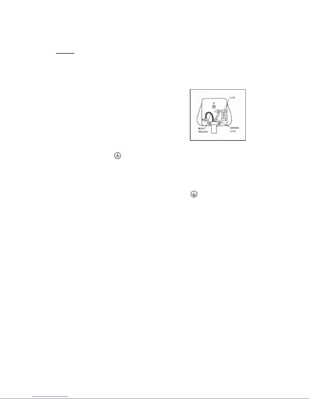
Mains plug replacement (UK & Ireland only)
If you need to replace the fitted plug of the tool, then follow the instruction below.
Machines that are connected direct to the mains supply
For Machines that are double insulated. Do not require a connection to earth.
If in doubt consult a Qualified Electrician.
The wires in this type of machine are coloured
In the following way.
Blue Neutral (N)
Brown Live (L)
Some machines come with an Earth wire this is as follows 13 amp fuse approved to BS 1363(A)
Green/Yellow Earth (E)
Always secure the wires in the plug terminals carefully, make sure no loose strands are left exposed as they can
short circuit and cause injury, fir and or damage the tool.
Secure the cable in the cord grip firmly
Never use a light socket.
Never connect the Live (L) or Neutral (N) wires to the Earth pin marked (E)
For model 1645 which is rated 115v and has a power rating exceeding 1500w. It is recommended to fit a plug to
BS4343 Standard DO NOT FIT A BS1363(A) TO 115v unit, as the voltage rating is different and connection to
the wrong supply voltage could result in a serious hazard.
NOTE: If your mains wires differ from the above consult a qualified Electrician. Always make sure the mains
supply is of the correct voltage and you use the correct rated fuse protection.
Regularly inspect all machines electrical connections and wiring condition for damage. Any faults detected should
be immediately rectified before further use of the machine. Always have the wiring checked by a qualified
electrician.
In use ensure all wiring and extension cords are kept clear of any cutting tool, sharp objects and any other
workshop hazards such as wet floors, chemicals, solvents etc.
This machines is protected by a 13amp fuse make sure the correct fuse is used.
To prevent fire or shock hazards, do not expose theses products to rain or moisture.
Page 13

CANNON TOOLS LTD
Add: 20 station road, Rowley Regis, west midlands,B65 OJU.U.K.
Made in china
This manual suits for next models
1
Table of contents
Popular Grinder manuals by other brands


Hilti
Hilti DAG 700-P Original operating instructions

Chicago Electric
Chicago Electric 97588 Set up and operating instructions

Craftex
Craftex CX905 user manual

joke
joke Turbo G 180/60 instruction manual

Metabo HPT
Metabo HPT G 12VE Safety instructions and instruction manual

Bosch
Bosch GBG 8 Original instructions

Chicago Pneumatic
Chicago Pneumatic CP875 instruction manual

Raider
Raider RDI-AG48 user manual

Greiner Vibrograf
Greiner Vibrograf SL1 operating manual

Hitachi
Hitachi G10SR3 user manual

Chicago Electric
Chicago Electric ITEM 69454 Owner's manual & safety instructions

Milwaukee
Milwaukee 6130-33 Operator's manual