Bose Sicilia Entero ESC User manual

Rev.1.0
Entero®VoiceAlarmsystem….
Entero®ESCinstallationmenuguide

ENTEROESC‐INSTALLATIONMENUGUIDE
2
Themanufacturerreservesspecificationprivileges.Informationinthismanualissubjecttochange
withoutpriornoticeorobligation.

ENTEROESC‐INSTALLATIONMENUGUIDE
3
TableofContents
Introduction...............................................................................................................................................................4
1.Indicators‐accesslevel1..................................................................................................................................5
1.1.Entero®ESCEmergencySystemController:..................................................................................................5
1.2.Entero®EvacuationpanelandFirepanel:.....................................................................................................5
1.3.Entero®ESAPowerAmplifier:.......................................................................................................................6
1.4.Entero®EPCEmergencyPowerController:...................................................................................................6
2.Indicatorsandcontrols–accesslevel2............................................................................................................7
2.1.Entero®ESCEmergencySystemController:..................................................................................................7
2.2Mainscreen...................................................................................................................................................8
2.3Systemmenu.................................................................................................................................................8
3.Systemconfiguration–accesslevel3.............................................................................................................11
4.Entero®FirePanelandEvacuationPanel:.......................................................................................................20
Appendix:Errormessages.......................................................................................................................................23

ENTEROESC‐INSTALLATIONMENUGUIDE
4
Introduction
Thisinstallermenuguideisintendedforthosepersonswhoaretrainedandauthorizedtooperateandconfigure
theEnteroVoiceAlarmControlandIndicatingEquipment(VACIE)ataccesslevel3.Thedifferentaccesslevels
formandatoryindicationsandcontrolsrelatedtomandatoryfunctionsaredefinedintheEN54‐16:2008
standard:
Accesslevel1‐Formember(s)ofthegeneralpublicorpersonshavingageneralresponsibilityforsafety
supervision,whomightbeexpectedtoinvestigateandinitiallyrespondtoafirealarmorafaultwarning.
Accesslevel2‐Forpersonshavingaspecificresponsibilityforsafetyandwhoaretrainedandauthorizedto
operatetheVACIEinthe:
quiescentcondition,
voicealarmoutputcondition,
faultwarningconditionand
disablementcondition.
Accesslevel3‐Forpersonswhoaretrainedandauthorized:
tore‐configurethesitespecificdataheldwithintheVACIEorcontrolledbyit(forexample;labeling,
alarmzoning,alarmorganization),
tostoreandchangeofemergencytonesandmessagesand
tomaintaintheVACIEinaccordancewiththemanufacturer'spublishedinstructionsanddata.
Accesslevel4‐ForpersonswhoaretrainedandauthorizedbythemanufacturertoeitherrepairtheVACIEor
alteritsfirmware,therebychangingitsbasicmodeofoperation.
Accessibilityofindicationsandcontrolsat:
Accesslevel1‐Allmandatoryindications(VoiceAlarmcondition,Generalerrors,SystemfaultsandPower
status)arevisiblewithouttheneedofmanualintervention
Accesslevel2‐Allmanualcontrolandindicatorsareaccessiblybyaspecialprocedure:
VACIE:requiresamechanicalkeywhichallowstoopenthefrontdooronly
Entero®FirePanel:requiresamechanicalkey(optional)toopenthedoor;anoptionalcode
(combinationofbuttonpresses)canbeusedinadditiontothis.
Entero®EvacuationPanel:requiresacode(combinationofbuttonpresses)toenableoperationofthe
panel.
Accesslevel3‐Requiresapasswordtoenterthesetup&configurationsectionoftheEntero®ESCunit,requires
specialtoolstoopenEnterocomponentsforaccesstointernalsettings&memorycardsandrequiresa
mechanicalkey(differentfromthefrontdoor)toopenthereardoorortoremovethesidepanelsoftheVACIE
cabinet.
Accesslevel4‐RequiresspecialtoolsandprogrammingdevicestoserviceorrepairEnterocomponents.

ENTEROESC‐INSTALLATIONMENUGUIDE
5
1. Indicators‐accesslevel1
1.1.Entero®ESCEmergencySystemController:
1. POWER–GREEN:indicatespowerstatus(both230Vacand/or48Vdc).Ifthisindicatorisnot
illuminated(OFF)both230Vacand48Vdcaredisconnected;thesystemisnotoperating.
2. SYSTEMFAULT–YELLOW:indicatesafailureoftheinternalMicroprocessororDatastorage.Whenthis
indicatoristurnedON,thesystemmaynotbeoperatingcorrectly;urgentserviceofthesystemis
required!Aninternalbuzzerwillalsosound.
3. GENERALERROR–YELLOW:indicatesafailureofmonitoredpartsofthesystemlike:amplifiers,
loudspeakerlinesandconnectionofemergencypanels.WhenthisindicatoristurnedON,thesystem
mayhaveseriouserrors;urgentserviceofthesystemisrequired!Aninternalbuzzerwillalsosound.
4. ALARM–RED:indicatesthepresenceofaVoiceAlarmcondition;anemergencymessageor
microphoneannouncementisactiveintheVoiceAlarmsystem.
1.2.Entero®EvacuationpanelandFirepanel:
1. 230Vac–GREEN:indicatesthe230Vacpowerstatus;whenOFFthepowersourceisdisconnected,or
theunitisnotyetcalibrated(48VdcindicatoralsoOFF).
2. 48Vdc–GREEN:indicatesthe48Vdcpowerstatus;whenOFFthepowersourceisdisconnected,orthe
unitisnotyetcalibrated(230VacindicatoralsoOFF).
3. ALARM–RED:indicatesthepresenceofaVoiceAlarmcondition;anemergencymessageor
microphoneannouncementisactiveintheVoiceAlarmsystem.
4. ERROR–YELLOW:combinedindicationofthe‘SYSTEMFAULT’and‘GENERALERROR’asindicatedon
theEnteroESC.WhenthisindicatoristurnedONthesystemmaynotbeoperatingcorrectly;urgent
serviceofthesystemisrequired!Aninternalbuzzerwillalsosound.
5. PanelDisabled‐YELLOW:innormaloperatingmodethisindicatorwillbeilluminatedifthepanel
disabledfunctionisactivated;itwillturnOFFwhentherightcode(keycombination)ispressed.Ifthe
paneldisabledindicatorflashesANDtheERRORindicator&BuzzerarealsoturnedON,the
1
2
3
4
1
2
3
4
5

ENTEROESC‐INSTALLATIONMENUGUIDE
6
communicationwiththeEnteroESCislost.Iftheunitisnotyetcalibrated,thisindicatorstarttoflash
afterabout60seconds.
1.3.Entero®ESAPowerAmplifier:
1. PROTECT–YELLOW:indicatestheprotectionstatusofanamplifierchannel(1‐8).Whentheindicatoris
ONthechannelisnotoperating.
2. 230Vac–GREEN:indicatesthepresenceofthe230Vacmainsvoltage.WhentheindicatorisOFF,the
230Vacpowersourceisdisconnected
3. 48Vdc–GREEN:indicatesthepresenceofthe48Vdcbatteryvoltage.WhentheindicatorisOFF,the48
Vdcpowersourceisdisconnected
4. ERROR–YELLOW:indicatesafaultofftheinternalpowersupply.Whentheindicatorisilluminated,the
amplifiermaynotbeoperatinganymore.
1.4.Entero®EPCEmergencyPowerController:
1. 230VacINPUT–GREEN/YELLOW:whenthisindicatorisGREENitshowsacorrectoperating230Vac
mainspowerinput;whentheindicatorischangedtoYELLOWthereisanerroronthe230Vacinput.
2. 48VdcINPUT–GREEN/YELLOW:whenthisindicatorisGREENitshowsacorrectoperating48Vdc
batterypowerinput;whentheindicatorischangedtoYELLOWthereisanerroronthe48Vdcinput.
3. 48VdcOUTPUT–GREEN/YELLOW:whenthisindicatorisGREENitshowsacorrectoperating48Vdc
outputs;whentheindicatorischangedtoYELLOWthereisanissueswith1ormore48Vdcoutputs.
NOTE:TheEnteroESAPowerAmplifiersandtheEnteroEPCEmergencyPowerControllerdonothaveany
controlswhichareaccessibleataccesslevel1&2.RefertotheESAandEPCinstallationguideformore
detailsandconfigurationoptionsataccesslevel3.
1
2
3
4
1
2
3

ENTEROESC‐INSTALLATIONMENUGUIDE
7
2. Indicatorsandcontrols–accesslevel2
2.1.Entero®ESCEmergencySystemController:
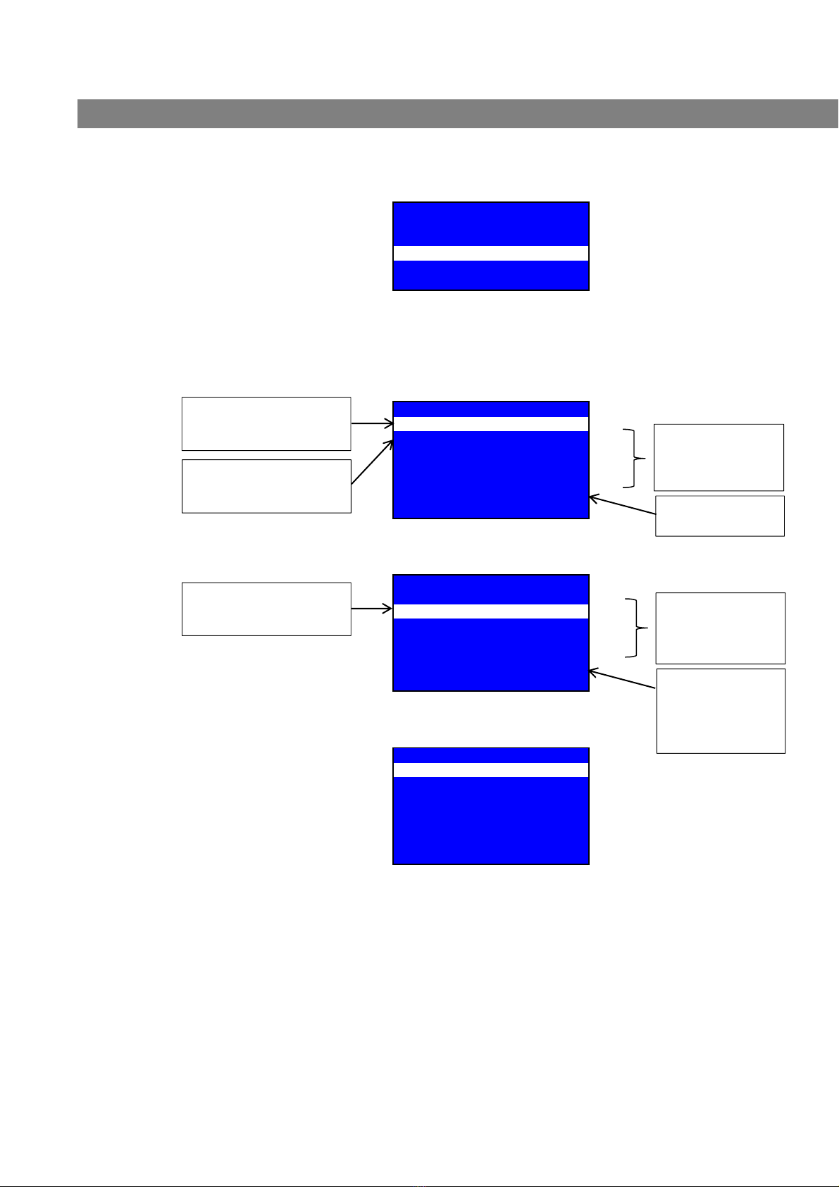
1. LCDdisplay:usedtoindicatetheunitsID,thestatusof230Vac,48Vdcandcommunication,butalsothe
numberofexisting&confirmederrorsandthenumberofoutputsintestmode.Differentmenuitems
areavailableintheSystemmenu.
ENTEROM1UNIT:OK
ACPower230V:OK
DCPower48V:OK48.3V
Communication:OK
Confirmederrors:0/0
Out
p
utsintestmode:0/12
SYSTEMMENU
2. Indicators:showthestatusofPOWER,SYSTEMFAULTS,GENERALERRORSandALARM.Seealso
‘Indicators–accesslevel1’aboveformoredetails.
3. Navigationbuttons:usethenavigationbuttonstoscrollthroughorselectdifferentmenuitems;

ENTEROESC‐INSTALLATIONMENUGUIDE
8
2.2Mainscreen
ENTEROM1UNIT:OK
ACPower230V:OK
DCPower48V:OK48.3V
Communication:OK
Confirmederrors:0/0
Outputsintestmode:0/12
SYSTEMMENU
Duringnormaloperatingmodethemainscreenindicatesthe:
deviceIDandoverallstatusofthedevice
230Vacpowerstatus
48Vdcpowerstatusandactualbatteryvoltage
Communicationstatus
‘Confirmederrors:0/0’‐showsthenumberofconfirmed&existingerrors>whenlineishighlighted,
pressOKtodirectlyenterthe‘Acknowledgederror’menu
‘Outputsintestmode:0/12’‐showsthenumberofoutputsintestmode(whicharetemporarynot
monitored)
Toenterthe‘SYSTEMMENU’,pressleftorrightbuttontojumptothisline&pressOK.
2.3Systemmenu
Whenthesystemmenuisenteredthefollowingmenuitemscanbeselected:
SYSTEMMENU
Systemoverview
Acknowledgeerror
Installationmenu
Buzzer/indicatortest
Reseterror
RETURN
Systemoverview
Systemoverviewshowsalistofallcomponentslikeamplifiers,loudspeakerslines,errorcontacts,
emergencypanelsandother,whichhavebeenfoundduringthecalibrationroutineofthesystem.
SYSTEMOVERVIEW
Speakerline1NoAmpfound!
Speakerline2A:98WB:30W
Speakerline3A:250WB:125W
Speakerline4A+B:Opn‐L
Speakerline5A:Opn‐LB:35W
Speakerline6A:98WB:30W
Speakerline7A:372WB:112W
Speakerline8NoAmpfound!
Speakerline9A+B:Opn‐L
Speakerline10A:473WB:Opn‐L
Speakerline11A:40WB:60W
Speakerline12NoAmpfound!
Backup‐Amp1forExp.Card123
Backup‐Amp2notinstalled
Backup‐Amp2notinstalled
StatusofLoudspeakerlines:
‘Noampfound!’=noamplifier
found;monitoringoflineisnot
possible(requiresamplifier)
‘250W’=foundloadonAorB
speakerline>lineismonitored
‘Opn‐L’=openline>noload
(between30Wand800W)found
onconnecteds
p
eakerline
(
s
)
StatusofBackupamplifiers:
‘forExp.Card123’=Backupamp
islinkedto4x4expansioncard
nr.1,2&3>Backupampwillbe
monitored
‘notinstalled’=noBackupamp
connected

ENTEROESC‐INSTALLATIONMENUGUIDE
9
Usetheup‐ordownbuttonstoscrollthroughthelist.Presstheleftorrightbuttonstojumpto‘RETURN”
andpresstheOKbuttontoreturntotheSYSTEMMENU.
Acknowledgeerror
The‘Acknowledgederror’menushowsanoverviewofallexistingerrorsandearlieracknowledgederrors
fromthatparticularunit.Ifallerrorsareacknowledgedthe‘Generalerror’indicatorwillstayilluminated,
astheerrorsarenotclearedyet;theinternalbuzzerwillturnoff.
ACKNOWLEDGEERROR
M1L5AopenLineerror
M1Evacpanel4MicLine2ackno
M1Slave1comackno
M1L12BopenLineackno
M1Firepanel1Com2ackno
......
RETURN
Toacknowledgeanerror;scrolltothelistederrorusingup&downbuttonsandpressOK;thefollowing
menuwillappear:
ACKNOWLEDGEERROR
M1L5AopenLineerror
Acknowledgethiserror?
<NO>
Use▲▼tochange,pressOK
Usetheupbuttonstochangefrom‘<NO>’to‘<YES>’andpressOKtoacknowledgetheerror.Toleavethis
windowwithoutacknowledgingtheerror;pressOKtoreturnwhen‘<NO>’isdisplayed.
Installationmenu
Seechapter‘Systemconfiguration–accesslevel3’formoredetails.
ExtSigAudionotinstalled
EPCerrorininstalled
Exterrorininstalled
Mainserrorininstalled
Power48Vdcinstalled
Wallcontr.1notinstalled
Wallcontr.2notinstalled
Wallcontr.3notinstalled
Wallcontr.4notinstalled
Firepanel1installed
Firepanel3installed
Evacpanel2installed
Evacpanel6installed
FDSmodule1installed
Slave1installed
Slave2installed
RETURN
StatusofExternalcontacts&inputs:
‘notinstalled’=contact/input
notfound
‘installed’=contact/inputfound
andwillbemonitored
StatusofWallcontrollers1to4(if
optionalcardisinstalled):
‘notinstalled’=notconnected
‘installed’=controller‘X’(1‐4)
foundtoselectsources(input1‐
4
)
andvolumeofout
p
ut‘X’
(
1‐4
)
StatusofEmergencypanels,FDS
interfaceandEnteroslavedevice(s):
showsIDoffounddevice(s)
devicewillbemonitoredwhen
displayed
NOTE: Seeappendixforan
overviewofallpossibleerrors.

ENTEROESC‐INSTALLATIONMENUGUIDE
10
Buzzer/indicatortest
Usethismenutoperformabuzzerandindicatortest.
BUZZER/INDICATOR TEST
Buzzerandindicator test
PressOKtostart
RETURN
PresstheOKbuttontostartthebuzzerandindicatortest;allindicatorsonthedevicewillilluminateand
thebuzzerwillbeaudible.After2secondsthistestwillstopautomatically.
Reseterror
Thereseterrormenushowsanoverviewofallexistingerrorsanderrorswhichhavebeenreset.Aslong
asnotallerrorsareresettheGeneralerrorand/orSystemFaultindicatorwillstayilluminated,whilethe
buzzeristurnedoff.
RESETERROR
M1L5AopenLineerror
M1Evacpanel4MicLine2 reset
M1Slave1com reset
M1L12BopenLineerror
M1Firepanel1MicLine1 reset
......
RETURN
Usetheup&downbuttonstoselecttheerrorandpressOK;thefollowingmenuwillappear:
RESETERROR
M1L5AopenLineerror
Resetthiserror?
<NO>
Use▲▼tochange,pressOK
Toresettheerror,usetheupbuttontochangefrom‘<NO>’to‘<YES>’andpressOK.Toleavethis
windowwithoutresettinganerror;pressOKtoreturnwhen‘<NO>’isdisplayed.
Ifallerrorsarereset,theGeneralerrorand/orSystemFaultindicator&internalbuzzerwillturnoff,
untilanewerrorisfoundinthesystem.Theseindicatorswillalsoturnoffontheconnectedemergency
panels.
Theerrorlogcanbeclearedintheinstallationmenuonly.
NOTE: Seeappendixforan
overviewofallpossibleerrors.

ENTEROESC‐INSTALLATIONMENUGUIDE
11
3. Systemconfiguration–accesslevel3
Installationmenu
Theinstallationmenucanbeusedforquickaccessofmostimportantsystemsettings.InaMaster/Slavesystem
setup,firstgotothemenu‘Rackmaster/slavesettings’toconfigureeachunit.
Toentertheinstallationmenuafourdigitpasswordisrequired.Usetheupanddownbuttontochangethefirst
digit(0‐9)andpressOK.Repeatthisfortheremaining3digits.Thedefaultpasswordtoentertheinstallation
menuis:1234,whichcanbechangedinaseparatemenu.Whentheinstallationmenuisenteredthefollowing
menuwillbedisplayed:
Installationmenu
1.Systemoverview
2.Testmodeoverview
3.Unitsetup
4.EmergencypanelsetupM1
5.Battery
6.Rackmaster/slavesettings
7.Calibratewholeunit
8.Errorlog
9.Clearerrorlog
10.Languageselection
11.Factoryrestore
12.Changepassword
RETURN
1. Systemoverview
Systemoverviewshowsalistofallcomponentslikeamplifiers,loudspeakerslines,errorcontacts,
emergencypanelsandother,whichhavebeenfoundduringthecalibrationroutineofthesystem.See
chapter2‘Indicatorsandcontrols–accesslevel2’formoredetails.
2. Testmodeoverview
Thetestmodeoverviewshowswhichoutputsareputintestmode;ifafailureisfoundonthisoutput,it
willnotbereported!
3. Testmodeoverview
Output1
Output2
..
Output12
Return
INSTALLATIONMENU
Pleaseenterpassword:0000
Use▲▼tochange,pressOK
RETURN

ENTEROESC‐INSTALLATIONMENUGUIDE
12
3. Unitsetup
IntheunitsetupmenuonecanchangetheAudioinputs,Zoneoutputsandstartaunitcalibration
3.Unitsetup
3.1Audioinputs
3.2Zoneoutputs
3.3Calibrateunit
RETURN
3.1 Audioinputs
ThenameoftheinputswillbedisplayedifenteredviatheEnteroinstallersoftware.
3.1Audioinputs
Input1–CDplayer
Input2‐Input
Input3–Input
Input4–Input
Input5–Input
Input6–Input
Input7–Input
Input8–Input
Input9–Input
Input10–Input
Input11–Input
Input12‐Input
Return
UsetheupanddownbuttonstoselectaninputandpressOK:thefollowingwillbedisplayed:
Input1–Input
Inputsensitivity<0dB>
Inputgain<0dB>
RETURN
Inputsensitivity:
Tochangetheinputsensitivity,pressOK:the‘0dB’valuewillnowhighlight.Usetheupand
downbuttonstochangeto:‐10dB,0dBor+3dB.PressOKagaintostorethenewvalue.
InputGain:
Tochangetheinputgain,selectmenuitemandpressOKtoselecttheinputgainvalue.Usethe
upanddownbuttonstochangethevaluebetween–80and+6dB;pressOKtostorethenew
value.
PresstheleftorrightbuttontojumptoRETURN,followedbyOKtoreturntopreviousmenu.

ENTEROESC‐INSTALLATIONMENUGUIDE
13
3.2 Zoneoutputs
Foreachindividualoutputthefollowingcanbeconfigured:outputgain,emergencygain,line
monitoringsettingsandchannellink.Thenameoftheoutputswillonlybedisplayedinthis
menuiftheyareenteredviatheEnteroinstallersoftware.
3.2Zoneoutputs
Output1–MeetingRoom1
Output2–MeetingRoom2
Output3–Output
Output4–Output
Output5–Output
Output6–Output
Output7–Output
Output8–Output
Output9–Output
Output10–Output
Output11–Output
Output12‐Output
Return
UsetheupanddownbuttonstoselectanoutputandpressOK;thefollowingwillbedisplayed:
Output2–MeetingRoom2
OutputGain<0dB>
Emergencygain<+1dB>
LineMonitoringPressOK
LinktoprevoutputPressOK
Useup/downtochange,pressOK
RETURN
OutputGain
Toadjusttheoutputgain(‐80to+6dB);usetheupanddownbuttonstoselectthesettingsand
pressOKtoselectvalue;useupanddowntochangevalueandpressOKtostore.
EmergencyGain
Toadjusttheleveloftheemergencysignal(‐80to+6dB)routedtothisoutputonly;usetheup
anddownbuttonstoselectthismenuitemandpressOKtoselectvalue;useupanddownto
changevalueandpressOKtostore.NOTE:theinputlevelsoftheemergencypanelinputs1&2
andthealarm1&2messagescanbeadjustedinmenu4‘Emergencypanelsetup’.
Linemonitoring:
Tosetuplinemonitoringsettings,ortomonitorthelineloadsaftercalibration;enterthismenu
item.Thefollowingwillbedisplayedincasenoamplifierandloudspeakerlinesareinstalledyet:
OUTPUT1LINEMONITORING
NoAmpinstalled!
Gotomonitoringsettings
RETURN
Select‘Gotomonitoringsettings’toconfigurethelinemonitoringsettingsandtoperforma
calibrationoftheselectedoutput:
ENTEROESC‐INSTALLATIONMENUGUIDE
14
Ifa50Vor100Vamplifier(Bridged),orif50Vamplifierwith100Vtransformer(TX)isinstalled,in
combinationwith1ormoreloudspeakerlines,thefollowingwindowwillbedisplayed:
OUTPUT1LINEMONITORING
‐100VAmpinstalled
Ampconnectedto:
Speakerline1PressOK
RETURN
Ifmorespeakerlinesareconnectedtothesameamplifier,usetheupanddownbuttonsto
select1ofthelistedspeaklines;pressOKtoviewthestatus&tochangethesettingsofthe
installedspeakerline(s).NOTE:thismenuisdividedinto4layers!
SPEAKERLINE1MONITORING1/4
LinestatusA+B:noerrors
Storedload20kHz[W]:
A:99B:50A+B:149
Actualload20kHz[W]:
A:97B:52A+B:149
Nextmeasurementin15s!
RETURN
Usethedownbuttontogotothenextwindow(2/4):
SPEAKERLINE1MONITORING2/4
Storedload1kHz[W]:
A:70B:35A+B:105
Actualload1kHz[W]:
A:n.a.B:n.a.A+B:n.a.
Nextmeasurementin5s!
RETURN
Usethedownbuttontogotothenextwindow(3/4):
SPEAKERLINE1MONITORING3/4
Speakerlineintestmode<NO>
Automeasurement1KHZ<YES>
Deviation(20k)<150W>
Deviation(1k)<50W>
ClearcalibrationPressOK
CalibrateoutputPressOK
RETURN
Speakerlineintestmode:
Totemporaryturnoffspeakerlinemonitoring,presstheOKbuttontoswitchfrom‘NO’
to‘YES’toputtheoutputintotestmode;noerrorswillbereported.Incaseashort
circuitoccursontheline;thelinewillstillbedisconnected.Iftheamplifierfailswhich
powersthisline,itwillswitchtoabackupamplifier!Themainscreenwillindicateifand
howmanyoutputsareputintestmode;notethisisonlyatemporaryfunctionfor
examplewhenserviceneedstotakeplaceonaspeakerline.Makesuretosettestmode
backtoNOwhenmaintenance/serviceofthesystemisfinished!
Usethedownbuttontogotothenextmenuline:
PresstheOKbuttonto
switchbetweenthestatuses
ofLineA
,
LineBorLineA+B Indicatesstoredand
actualloadat20kHz
forLineA,LineBand
the sum of Line A+B
Iflineisselected:
PressOKtoswitchbetween
LoadshowninWattorOhm Indicateswhennext
measurementstarts
Indicatesstoredand
actualloadat1kHz
forLineA,LineBand
thesumofLineA+B
Iflineisselected:
PressOKtoswitchbetween
LoadshowninWattorOhm
1kHzmeasurement
(ifactivated)only
takesplaceswhen
multiplefailuresare
foundat20kHz!

ENTEROESC‐INSTALLATIONMENUGUIDE
15
Automeasurement1kHz:
Incaseafailureonaspeakerlineisfound5times,aquick1kHzmeasurementwilltake
placetoconfirmthefoundfailure,beforeanerrorisreported.Ifnofailureisfoundat1
kHz,thestoredloadvalueat20kHzwillbeadjustedtotheactualfoundloadvalue.To
turnthe‘1kHzautomeasurement’OFF;pressOKtoswitchbetween‘YES’and‘NO’.
Usethedownbuttontogotothenextmenuline:
Deviation(20kHz)&Deviation(1kHz):
PresstheOKbuttontoswitchbetween5%,10%,20%,30%(default)or50%deviationof
theloudspeakerlinebeforeanerrorisdisplayed.ThedeviationisshowninWatt(W):
abovepercentagesoftheinstalledspeakerlineloadareusedtoindicatethedeviation
options.Ifthedeviationinpercentageoftheloadisbelow10W,theminimumdeviation
of10Wisdisplayed.
Usethedownbuttontogotothenextmenuline:
Clearcalibration:
PressOKtoclearacalibratedspeakerline.Usetheupanddownbuttontochange<NO>
to<YES>andpressOKtoclearandreturntothepreviousmenuposition.
Clearthisspeakerline?
<NO>
Useup/downtochange,pressOK
Usethedownbuttontogotothenextmenuline:
Calibrateoutput:
PressOKtocalibratespeakerlinesconnectedtothisoutput.Usetheupanddown
buttontochange<NO>to<YES>andpressOKtostartcalibration.
Calibratethisspeakerline?
<NO>
Useup/downtochange,pressOK
Aftercalibration,thepreviousmenuposition(3/4)isselectedautomatically.
Usethedownbuttontogotothenextwindow(4/4):
SPEAKERLINE1MONITORING4/4
Pilotfrequency(kHz)<20>
RETURN
Pilotfrequency:
Tochangethefrequencyofthepilottonemeasurement,presstheOKbuttontoswitch
between18,19,20,21and22kHz.Iftheoutputwasalreadycalibratedmakesureto
firstclearthiscalibrationbeforethepilotfrequencyischanged.Afteranewfrequency
hasbeenselected,theoutputneedstobecalibratedagain!

ENTEROESC‐INSTALLATIONMENUGUIDE
16
Linkoutputtopreviousoutput:
Enterthismenutolinktheoutputtothepreviousoutput.Usetheupanddownbuttonto
switchbetween<NO>and<YES>;if<YES>isselected,pressOKtoactivatethelinkandtoreturn
tothepreviousmenuposition.NOTE:output1cannotbelinked.
Linktoprevoutput
Linktooutput1<NO>
Useup/downtochange,pressOK
UsetheEnteroinstallersoftwareformorelinkoptionscombinedwithdelayonoutput2&3.
3.3 Calibrateunit
Tomonitorconnectedamplifiers,loudspeakerlines,external(error)contacts,48Vdcinputand
emergencypanels&externalaudioinput,thesefirstneedtobecalibrated(installed).Use
belowwindowto‘SelectAll’,or1ormoreindividualitemstocalibrate.Foroutput/loud
speakerlinecalibration;selectthetypeoflineconnected,100Vorlowimpedance.Incasean
outputneedstobeclearedatthesametime,select‘CLR’.Forallotheritems,selectYESorNO.
3.3CalibrateUnit
SelectallNO
Output1100V
Output2CLR
Output3L‐Imp
Output4YES
Output5NO
Output6NO
Output7NO
Output8NO
Output9NO
Output10NO
Output11NO
Output12NO
EmergencypanelsNO
ExtContacts/48VoltDCNO
SlavesNO
Calibrateselecteditems?
Return
Scrolltothebottomofthelisttoenter‘Calibratedselectitems’:
Calibrateselecteditems?
<NO>
Useup/downtochange,pressOK
Usetheupanddownbuttontoswitchbetween<NO>and<YES>;if<YES>isselected,pressOK
tostartcalibration.Whenthecalibrationisfinished,a‘SystemOverview’willbedisplayed
indicatingallcalibrateditems.
NOTE:iftheoptionalEnteroESCzonecontrollercardisinstalled,set‘Ext.Contacts/48Vdc’to
YEStosearchforconnecteduserinterfaces.Whenauserinterfacesinmovedtoadifferent
locationinthebuildinganewcalibrationmustbeperformedagain!

ENTEROESC‐INSTALLATIONMENUGUIDE
17
4. EmergencypanelsetupM1
IntheEmergencypanelsetupmenu,onecanadjusttheinputlevelsoftheemergencysignalinputs.
ChangingthislevelaffectsthegainforallemergencypanelsconnectedtothatspecificinputANDthe
adjustmentaffectstheleveloftheemergencysignalroutedtoalloutputs!
4.EmergencypanelsetupM1
4.1Emergencyinputlevels
RETURN
PressOKtoentermenu.
4.1 Emergencyinputlevels
4.1Emergencyinputlevels
Alarmmessage1<0dB>
Alarmmessage2<‐1dB>
Emergencypanelbus1<‐10dB>
Emergencypanelbus2<‐4dB>
Ext.signalinput<+3dB>
RETURN
UsetheupanddownbuttonstoselectAlarmmessage1or2,oroneoftheemergency
inputsandpressOKtoselectthecurrentgainvalue;usetheupanddownbuttonsto
changethisvalueandpressOKtostore.
5. Battery
ThebatterymenudisplaystheactualvoltageofthesecondarypowersourceconnectedtotheEnteroESC:
5.Battery
Batteryvoltage:48.5Vdc
RETURN
6. RackMaster/Slavesettings
EnterothismenutosetuptheunitasMasterorSlave1to31:
6.RackMaster/SlaveSettings
Rack<Master>
Firmwareversion:01‐00‐08
Useup/downtochange,pressOK
RETURN
UsetheupanddownbuttonstochangetheunitsIDandpressOKtoconfirm.
Thefirmwareversion(example:01‐00‐08)oftheunitisalsodisplayed.

ENTEROESC‐INSTALLATIONMENUGUIDE
18
7. Calibratewholeunit
Enterthismenutoquicklycalibratethecompleteunit:
Calibratewholeunit?
<NO>
Useup/downtochange,pressOK
Usetheupanddownbuttontoswitchbetween<NO>and<YES>;if<YES>isselectedpressOK.When
calibrationisfinished,a‘SystemOverview’willbedisplayedindicatingallcalibrateditems.
8. ErrorLog
Enterthismenutodisplayanoverviewofall(new&reset)errorsinthesystem:
8.Errorlog
M1L5AopenLineerror
M1Evacpanel4MicLine2reset
M1Slave1comreset
M1L12BopenLineerror
M1Firepanel1MicLine1reset
RETURN
UsetheupanddownbuttonstoselectanactiveerrorandpressOK:
8.Errorlog
M1L5AopenLineerror
Resetthiserror?
<NO>
Useup/downtochange,pressOK
Toresettheerror,usetheupanddownbuttontoswitchbetween<NO>and<YES>;if<YES>is
selectedpressOKtoreset.
9. Clearerrorlog
Enterthismenutocleartheerrorlog:
9.Clearerrorlog
Clearwholeerrorlog?
<NO>
Useup/downtochange,pressOK
Usetheupanddownbuttontoswitchbetween<NO>and<YES>;if<YES>isselectedpressOKtoclear
theerrorlogandreturntopreviousmenu.
NOTE:Seeappendixforan
overviewofallpossibleerrors.

ENTEROESC‐INSTALLATIONMENUGUIDE
19
10. Languageselection
TochangetheselectedlanguageoftheESCunit,enterthismenu:
LANGUAGESELECTION
1.English(Default)
2.Deutsch(German)
RETURN
UsetheupanddownbuttonstoselecttherightlanguageandpressOK.Inafewsecondsallmenuitems
willchangetotheselectedlanguage.
11. Factoryrestore
Enterthismenutorestoretheunittofactorydefaultsettings:
11.Factoryrestore
Factoryrestorethisunit?
<NO>
Useup/downtochange,pressOK
Usetheupanddownbuttontoswitchbetween<NO>and<YES>;if<YES>isselectedpressOKtoperform
afactoryrestore.
12. Changepassword
Enterthismenutochangethepasswordtoentertheinstallationmenu:
Installationmenu
Enternewpassword:0000
Useup/downtochange,pressOK
RETURN
Usetheupanddownbuttontochangethe4digits(between0000and9999);confirmeachentereddigit
bypressingtheOKbutton.
NOTE:ALLSETTINGSWILLGETLOST!

ENTEROESC‐INSTALLATIONMENUGUIDE
20
4. Entero®FirePanelandEvacuationPanel:
AllcontrolsandindicatorsontheEnteroFirePanel(FP)andEnteroEvacuationPanelsharethesame
functionality;therefortheuserinstructionsareexplainedusingtheEvacuationPanellayout.
RefertotheEnteroESCinstallationguideforconfigurationataccesslevel3!
Emergencypanelpriorities:
PriorityhandlingofeachpaneltypeisdefinedbytypeandIDnr.ofthepanel(whereID1hashighestpriority
andID32lowestpriority).Theseprioritiescanonlybeconfiguredduringsetupofthesystemandcannotbe
changedbytheuserofthesystem.Inorderofpriority:
1. FirePanelmicrophone
2. EvacuationPanelmicrophone
3. FireDetectionSysteminterfacemic./lineinput
4. FirePanelalarmmessage(s)
5. EvacuationPanelalarmmessage(s)
6. FireDetectionSysteminterface
7. ExternalAudioinput
NOTE:theFireDetectionSysteminterfaceandtheExternalAudioinputhavenomanualcontrolsandare
thereforenotcoveredinthismanual.
Fire/EvacuationPanel‐maincontrol 12Buttonexpansionboard
Lamptest:
Pressandholdthe‘LampTest’buttontotestallindicatorsandtheinternalbuzzer.
Resetbuzzer:
WhenthereisanerrorinthesystemtheERRORindicatorwillilluminateandtheinternalbuzzerwillturnon.
Tode‐activatetheinternalbuzzer,pressthe‘ResetBuzzer’button.Whenmultipleemergencypanelsareusedin
thesystem;thisresetbuzzerfunctionwillde‐activatedebuzzerineachindividualpanel.
Table of contents
Popular Security System manuals by other brands

Eaton
Eaton i-on Series Administration and User Manual

YOKOGAWA
YOKOGAWA JUXTA VJ Series user manual

Eaton
Eaton FX6100 Installation and operation manual

Pyronix
Pyronix RINS1902-2 user manual

Radio Shack
Radio Shack 49-421A owner's manual

Hansson PyroTech
Hansson PyroTech IKAROS MANOVERBOARD LIGHT AND SMOKE Mounting and operating instructions


 user guide")


