System Configurations
The Bose®Panaray®502®system
provides a flexible, building-block
approach to fit the sound reinforce-
ment requirements of many types of
applications, from nightclubs to
cathedrals. Detailed installation and
system design guidelines for the
Panaray 502 system are provided in
the Panaray 502 System Owner’s
Guide. For illustrative purposes, here
are some typical system configura-
tions:
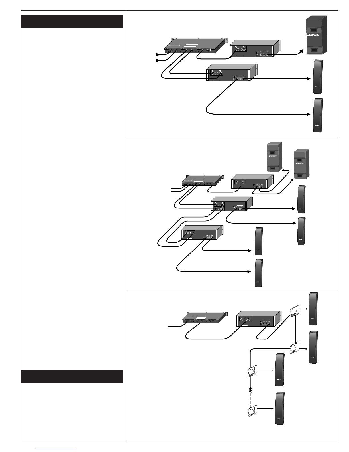
Figure 1 shows a block diagram of
the basic Panaray 502 system,
consisting of one 502 B, two 502 A
speakers, one Panaray system digital
controller, and three channels of
amplification for a stereo system.
This system provides 115dB-SPL @
1 m average acoustic output. Addi-
tional low-frequency output can
easily be achieved by locating the
cabinet against large hard surfaces.
Figure 2 illustrates how components
can be added to the basic Panaray
502 system to achieve a variety of
SPL or coverage requirements. One
example of an expanded system
would be a small disco dance area.
In this application, four arrays at the
outer corners of the dance floor,
plus two 502 Bs on the floor adjacent
to the dance area, will deliver
approximately 118dB-SPL average,
with 130dB-SPL peaks, and all
components driven at maximum
recommended amplifier power.
Figure 3 shows how the Panaray 502
components can be interconnected
for a voice-only paging system. This
system is ideal for applications where
voice reinforcement is needed over a
large area, such as an airport termi-
nal or a train station. Through the use
of the Bose CVT-5 Constant Voltage
Transformer, multiple 502 As can be
installed in a 70/100V constant
voltage distributed system. (This
system operates from 130Hz and
above only, and is not recommended
for use where music is an integral
part of the program material.)
Figure 1: Basic Panaray system
Figure 2: Expanded Panaray system
Figure 3: Distributed voice-only system
Panaray system digital controller
Panaray system digital controller
Panaray system digital controller
The Bose Panaray 502 A controlled
array and the 502 B Acoustimass
enclosures are covered
by a five-year, transferable limited
warranty.
Warranty Information
®®
SER.NO. D.O.M.
CH1
INPUTLEVEL
–10 +4
INPUT
CH2
INPUTLEVEL
–10 +4
MODE
4
1
2
3
PROTECTEDBYU.S.PATENT 3,038,964
REFERTO YOURINSTRUCTION MANUAL FOR PROPER INSTALLATION
ANDOPERATING PROCEDURES.INCORRECT WIRING MAY RESULT IN
DAMAGEAND/OR POOR PERFORMANCE.
CAUTION AVIS
RISKOF ELECTRICAL SHOCK
DONOT OPEN RISQUEDE CHOC ELECTRIQUE
NEPASOUVRIR
WARNING:
TOREDUCE THE RISK OF FIRE OR ELECTRICAL SHOCK
DONOT EXPOSE THIS EQUIPMENTTO RAIN OR MOISTURE.
MODE SWITCH GUIDE
POSITION OPERATINGMODE
4
2-WAYWITHLOW FREQUENCY OPTION
(NOTUSED)
3
STANDARD2-WAY(WITH 502B)
2
VOICEONLY/FULL RANGE (WITH 502A)
1
HIGH
FREQ
OUTPUT
CH1 CH2
LOWFREQ
LEVEL
0
.
.
.
.
.
.
.
+3
-18
BOSECORPORATION,FRAMINGHAM, MA 01701-9168
ENGINEEREDANDMANUFACTURED IN U.S.A.
OUTPUTMODE
NORM SUM
LOW
FREQ
OUTPUT
CH1 CH2
230V
~
AC
50/60Hz 12W
INPUTB
INPUTB INPUTA
BRIDGE
INPUTA
220 V
~
MADEIN USA
CAUTION
Inorder to grant a secure operation do not mount the amplifier in
afully closed housing. To preven electric shock, do not remove
cover.Disconnect power line in case of servicing.
ACHTUNG:
Umsichere Funktion zu gewährielsten, Gerät nicht in vollständig
geshlossenesGehäuse einbauen. Abdeckung während des
Betriebesnicht entfernen. Bor Offnen des Gerätes Netzstecker
ziehen.
BoseCorporation, Framinhman 01701, Mass, U.S.A.
SerialNo.:
Madein Germany
OUTPUTB BRIDGEOUTPUT OUTPUTA
ON
OFF
®®
502 A
(Left)
502 A
(Right)
L
R
Amplifier
Low Frequency
Output
R
R
L
L
High
Frequency
Output
Amplifier
From
Pre-amplifier
®®
®®
®®
®®
INPUTB
INPUTB INPUTA
BRIDGE
INPUTA
220 V
~
MADEIN USA
CAUTION
Inorder to grant a secure operation do not mount the amplifier in
afully closed housing. To preven electric shock, do not remove
cover.Disconnect power line in case of servicing.
ACHTUNG:
Umsichere Funktion zu gewährielsten, Gerät nicht in vollständig
geshlossenesGehäuse einbauen. Abdeckung während des
Betriebesnicht entfernen. Bor Offnen des Gerätes Netzstecker
ziehen.
BoseCorporation, Framinhman 01701, Mass, U.S.A.
SerialNo.:
Madein Germany
OUTPUTB BRIDGEOUTPUT OUTPUTA
ON
OFF
SER.NO. D.O.M. CH1
INPUTLEVEL
–10 +4
INPUT
CH2
INPUTLEVEL
–10 +4
MODE
4
1
2
3
PROTECTEDBYU.S.PATENT3,038,964
REFERTOYOUR INSTRUCTIONMANUAL FOR PROPER INSTALLATION
ANDOPERATINGPROCEDURES. INCORRECT WIRING MAYRESULT IN
DAMAGEAND/ORPOOR PERFORMANCE.
CAUTION AVIS
RISKOFELECTRICAL SHOCK
DONOTOPEN RISQUEDECHOCELECTRIQUE
NEPASOUVRIR
WARNING:
TOREDUCETHE RISK OF FIRE OR ELECTRICAL SHOCK
DONOTEXPOSE THIS EQUIPMENT TO RAIN OR MOISTURE.
MODESWITCH GUIDE
POSITION OPERATINGMODE
4
2-WAYWITHLOW FREQUENCY OPTION
(NOTUSED)
3
STANDARD2-WAY(WITH 502B)
2
VOICEONLY/FULLRANGE (WITH 502A)
1
HIGH
FREQ
OUTPUT
CH1 CH2
LOWFREQ
LEVEL
0
.
.
.
.
.
.
.
+3
-18
BOSECORPORATION,FRAMINGHAM,MA 01701-9168
ENGINEEREDANDMANUFACTUREDIN U.S.A.
OUTPUTMODE
NORM SUM
LOW
FREQ
OUTPUT
CH1 CH2
230V
~
AC
50/60Hz 12W
INPUTB
INPUTB INPUTA
BRIDGE
INPUTA
220 V
~
MADEIN USA
CAUTION
Inorder to grant a secure operation do not mount the amplifier in
afully closed housing. To preven electric shock, do not remove
cover.Disconnect power line in case of servicing.
ACHTUNG:
Umsichere Funktion zu gewährielsten, Gerät nicht in vollständig
geshlossenesGehäuse einbauen. Abdeckung während des
Betriebesnicht entfernen. Bor Offnen des Gerätes Netzstecker
ziehen.
BoseCorporation, Framinhman 01701, Mass, U.S.A.
SerialNo.:
Madein Germany
OUTPUTB BRIDGEOUTPUT OUTPUTA
ON
OFF
INPUTB
INPUTB INPUTA
BRIDGE
INPUTA
INPUTB
INPUTB INPUTA
BRIDGE
INPUTA
220 V
~
MADEIN USA
CAUTION
Inorder to grant a secure operation do not mount the amplifier in
afully closed housing. To preven electric shock, do not remove
cover.Disconnect power line in case of servicing.
ACHTUNG:
Umsichere Funktion zu gewährielsten, Gerät nicht in vollständig
geshlossenesGehäuse einbauen. Abdeckung während des
Betriebesnicht entfernen. Bor Offnen des Gerätes Netzstecker
ziehen.
BoseCorporation, Framinhman 01701, Mass, U.S.A.
SerialNo.:
Madein Germany
OUTPUTB BRIDGEOUTPUT OUTPUTA
ON
OFF
Bass amplifier
High frequency
amplifier one 502 A
502 A
502 A
502 A
High frequency
amplifier two
502 B
502 B
INPUTB
INPUTB INPUT A
BRIDGE
INPUTA
220 V
~
MADEIN USA
CAUTION
Inorder to grant a secure operation do not mount the amplifier in
afully closed housing. To preven electric shock, do not remove
cover.Disconnect power line in case of servicing.
ACHTUNG:
Umsichere Funktion zu gewährielsten, Gerät nicht in vollständig
geshlossenesGehäuse einbauen. Abdeckung während des
Betriebesnicht entfernen. Bor Offnen des Gerätes Netzstecker
ziehen.
BoseCorporation, Framinhman 01701, Mass, U.S.A.
SerialNo.:
Madein Germany
OUTPUTB BRIDGEOUTPUT OUTPUTA
ON
OFF
SER.NO. D.O.M.
CH1
INPUTLEVEL
–10 +4
INPUT
CH2
INPUTLEVEL
–10 +4
MODE
4
1
2
3
PROTECTEDBYU.S.PATENT3,038,964
REFERTOYOUR INSTRUCTION MANUALFOR PROPER INSTALLATION
ANDOPERATINGPROCEDURES. INCORRECT WIRING MAYRESULT IN
DAMAGEAND/ORPOOR PERFORMANCE.
CAUTION AVIS
RISKOFELECTRICAL SHOCK
DONOTOPEN RISQUEDE CHOC ELECTRIQUE
NEPASOUVRIR
WARNING:
TOREDUCETHE RISK OF FIRE OR ELECTRICAL SHOCK
DONOT EXPOSETHIS EQUIPMENT TO RAIN OR MOISTURE.
MODESWITCH GUIDE
POSITION OPERATINGMODE
4
2-WAYWITHLOW FREQUENCY OPTION
(NOTUSED)
3
STANDARD2-WAY(WITH 502B)
2
VOICEONLY/FULLRANGE (WITH 502A)
1
HIGH
FREQ
OUTPUT
CH1 CH2
LOWFREQ
LEVEL
0
.
.
.
.
.
.
.
+3
-18
BOSECORPORATION,FRAMINGHAM,MA 01701-9168
ENGINEEREDANDMANUFACTUREDIN U.S.A.
OUTPUTMODE
NORM SUM
LOW
FREQ
OUTPUT
CH1 CH2
230V
~
AC
50/60Hz 12W
®®
®®
®®
®®
502 A
502 A
502 A
502 A
CVT-5
CVT-5
CVT-5
CVT-5
From
High frequency
Constant voltage amplifier
502 B