Bossard 035/E32V User manual
OPERATORS MANUAL FOR
ELECTRIC SCREWDRIVERS
for self-cutting Threaded Inserts

2
1. BOSSARD DISCLAIMER 3
2. INTRODUCTION 4
3. SCREWDRIVER 5
3.1 IMPORTANT INSTALLATION & SAFETY . . . . . . . . . . . . . . . . . . . . . . . . . . . . . . . . . . . . . . . . . . . . . . . . 5
3.2 SETTING UP YOUR SCREWDRIVER AND CONTROLLER. . . . . . . . . . . . . . . . . . . . . . . . . . . . . . . . . . . . 6
3.3 BEFORE YOU TURN ON THE CONTROLLER . . . . . . . . . . . . . . . . . . . . . . . . . . . . . . . . . . . . . . . . . . . . . . 7
3.4 OPERATING THE SCREWDRIVER . . . . . . . . . . . . . . . . . . . . . . . . . . . . . . . . . . . . . . . . . . . . . . . . . . . . . . . 8
3.5 SETTING THE TORQUE . . . . . . . . . . . . . . . . . . . . . . . . . . . . . . . . . . . . . . . . . . . . . . . . . . . . . . . . . . . . . . . . 8
3.6 GENERAL SCREWDRIVER LAYOUT . . . . . . . . . . . . . . . . . . . . . . . . . . . . . . . . . . . . . . . . . . . . . . . . . . . . . 9
3.7 MODEL NUMBERS AND SPECIFICATIONS . . . . . . . . . . . . . . . . . . . . . . . . . . . . . . . . . . . . . . . . . . . . . . 10
3.7.1 32VDC CESL8 SCREWDRIVERS . . . . . . . . . . . . . . . . . . . . . . . . . . . . . . . . . . . . . . . . . . . . . . . . . . . . . . 10
3.7.2 40VDC CESL8 SCREWDRIVERS . . . . . . . . . . . . . . . . . . . . . . . . . . . . . . . . . . . . . . . . . . . . . . . . . . . . . . 10
3.7.3 POWER SUPPLY/CONTROLLER SPECIFICATIONS . . . . . . . . . . . . . . . . . . . . . . . . . . . . . . . . . . . . . . 10
3.8 SLOW START / OUTPUT SIGNAL MODULES . . . . . . . . . . . . . . . . . . . . . . . . . . . . . . . . . . . . . . . . . . . . . 11
3.9 ACCESSORIES AND PARTS . . . . . . . . . . . . . . . . . . . . . . . . . . . . . . . . . . . . . . . . . . . . . . . . . . . . . . . . . . . 11
3.10 SERV ICE . . . . . . . . . . . . . . . . . . . . . . . . . . . . . . . . . . . . . . . . . . . . . . . . . . . . . . . . . . . . . . . . . . . . . . . . . . 11
3.11 WARRANTY . . . . . . . . . . . . . . . . . . . . . . . . . . . . . . . . . . . . . . . . . . . . . . . . . . . . . . . . . . . . . . . . . . . . . . . . 11
4.0 SCREWDRIVER CONTROLLER 12
4.1 IMPORTANT INSTALLATION & SAFETY . . . . . . . . . . . . . . . . . . . . . . . . . . . . . . . . . . . . . . . . . . . . . . . 12
4.2 SPECIFICATIONS . . . . . . . . . . . . . . . . . . . . . . . . . . . . . . . . . . . . . . . . . . . . . . . . . . . . . . . . . . . . . . . . . . . . 13
4.3 GENERAL CONTROLLER OVERVIEW . . . . . . . . . . . . . . . . . . . . . . . . . . . . . . . . . . . . . . . . . . . . . . . . . . . 15
4.4 GETTING STARTED . . . . . . . . . . . . . . . . . . . . . . . . . . . . . . . . . . . . . . . . . . . . . . . . . . . . . . . . . . . . . . . . . . 15
4.5 KEYPAD AND PROGRAMMING BASICS . . . . . . . . . . . . . . . . . . . . . . . . . . . . . . . . . . . . . . . . . . . . . . . . . 16
4.6 PROGRAM OPTIONS AND EDITING . . . . . . . . . . . . . . . . . . . . . . . . . . . . . . . . . . . . . . . . . . . . . . . . . . . . 17
4.6.1 SEQUENCE NUMBER SL . . . . . . . . . . . . . . . . . . . . . . . . . . . . . . . . . . . . . . . . . . . . . . . . . . . . . . . . . . . 17
4.6.2 BATCH COUNT SETTING SC. . . . . . . . . . . . . . . . . . . . . . . . . . . . . . . . . . . . . . . . . . . . . . . . . . . . . . . . 17
4.6.3 END OF BATCH RESET TIME RT . . . . . . . . . . . . . . . . . . . . . . . . . . . . . . . . . . . . . . . . . . . . . . . . . . . . 17
4.6.4 SLOW START TIME RC AND SLOW START SPEED SP. . . . . . . . . . . . . . . . . . . . . . . . . . . . . . . . . . 17
4.6.5 MAXIMUM AND MINIMUM RUNDOWN TIME SETTINGS HT, LT . . . . . . . . . . . . . . . . . . . . . . . . . . 18
4.6.6 RECONFIRM TIME LL. . . . . . . . . . . . . . . . . . . . . . . . . . . . . . . . . . . . . . . . . . . . . . . . . . . . . . . . . . . . . . 18
4.6.7 DETAILED PROGRAM EDITING. . . . . . . . . . . . . . . . . . . . . . . . . . . . . . . . . . . . . . . . . . . . . . . . . . . . . . . 19
4.6.8 SCREWDRIVER SPEED ADJUSTMENTS . . . . . . . . . . . . . . . . . . . . . . . . . . . . . . . . . . . . . . . . . . . . . . . 22
4.6.9 AUDIBLE ALARM SETTINGS / OK AND NG LIGHTS. . . . . . . . . . . . . . . . . . . . . . . . . . . . . . . . . . . . . . 22
4.6.10 INPUT / OUTPUT CONNECTOR. . . . . . . . . . . . . . . . . . . . . . . . . . . . . . . . . . . . . . . . . . . . . . . . . . . . . . 23
4.6.11 DIP SWITCH SETTINGS . . . . . . . . . . . . . . . . . . . . . . . . . . . . . . . . . . . . . . . . . . . . . . . . . . . . . . . . . . . . 24
4.6.12 DISPL AY CODE S . . . . . . . . . . . . . . . . . . . . . . . . . . . . . . . . . . . . . . . . . . . . . . . . . . . . . . . . . . . . . . . . . . 26
4.6.13 SERVICE . . . . . . . . . . . . . . . . . . . . . . . . . . . . . . . . . . . . . . . . . . . . . . . . . . . . . . . . . . . . . . . . . . . . . . . . . 26
4.6.14 WARRANTY . . . . . . . . . . . . . . . . . . . . . . . . . . . . . . . . . . . . . . . . . . . . . . . . . . . . . . . . . . . . . . . . . . . . . . 26
ELECTRIC SCREWDRIVERS FOR SELFCUTTING THREADED INSERTS
TABLE OF CONTENT

3
ELECTRIC SCREWDRIVERS FOR SELFCUTTING THREADED INSERTS
1. BOSSARD DISCLAIMER
For the attention of the end-user
Bossard INSTALLATION EQUIPMENT
Please nominate a contact who can be kept updated of any changes to the equipment and return this
sheet to Bossard. Where applicable, it is also supplied with quotations.
COMPANY_______________________________________________________________________________ (print please)
NOMINATED CONTACT____________________________________DEPARTMENT_______________________________
TELEPHONE NUMBER & EXTENSION___________________________________________________________________
DISCLAIMER
This equipment supplied for_______________________________________________________(customer & country)
OnShipmentNumber___________________________________________________________________________________
Dated____________________________________
…should not be put into production use until the attached manual is understood. In some instances,
operating instructions, are included, and these are detailed on the packing list attached, the contents of
which should be confirmed as present by the customer. No warranty claims will be considered if the fault
is due to misuse or lack of precautions previously brought to your attention. Repairs will then be charged
at cost, including carriage.
The standard equipment is designed for reasonable use at an economic price. Where this is of an exces-
sive nature, either through continual use or the arduous nature of the operation, the warranty period
reduces accordingly. Bossard and their suppliers, if applicable, will adopt a reasonable attitude to this
reduction after consultation with the customer on the basis of commercial common sense. Modifications
to the equipment, where applicable, will be charged at cost.
It is the customer’s responsibility to order sufficient recommended spares to service the equipment as
detailed in the literature, and consideration should be given to duplicating complete units if the operation
is critical through either time of completion or production volume.
Ideally, one individual should be made responsible for maintaining the equipment. In the case of malfun-
ction of a specific piece of equipment, confirmed after discussion with Bossard, within a twelve-month
period from receipt of goods or proportionally less if the working day is greater than eight hours, Bossard
reserves the right to request the equipment be sent direct to the manufacturer of the original equipment.
Serial numbers and part numbers where applicable should always be stated on the paperwork.

4
ELECTRIC SCREWDRIVERS FOR SELFCUTTING THREADED INSERTS
2. INTRODUCTION
This manual has been published to offer assistance in the set-up, operation and maintenance of the
machine you recently purchased from Bossard.
Before you operate the machine please ensure that you have read and fully understood this manual.
Should you have any questions or queries relating to the operation and use of this machine, please contact
your local Bossard customer service. https://www.bossard.com/global-en/about-us/contact/

5
ELECTRIC SCREWDRIVERS FOR SELFCUTTING THREADED INSERTS
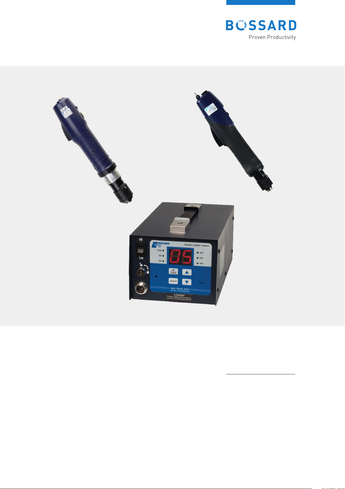
3. Screwdriver
32V and 40VDC 035/E/A CESL8 Brushless
Screwdrivers and Controllers - Operation Manual
CAUTION – Please read, understand, and follow all operating and safety instructions in this manual before
using the tools and controllers.
The 035/E/A / CESL8 Series Brushless tools are designed for exclusive use with specific Delta Regis cont-
rollers as defined in this manual. Do not attempt to use the tools and/or controllers with any products other
than as specified in this manual.
3.1 IMPORTANT INSTALLATION & SAFETY
1. Please read and understand the operation manual and follow all safety and operation instructions
2. Use these products in a suitable dry, indoor location. Do not use tools and controllers in damp, wet or
high temperature environments. Do not use in the presence of flammable liquids or gases.
3. Ensure that the controller has proper ventilation. Do not expose the tools and controllers to areas sub-
ject to airborne contaminants (eg. dust, metal filings).
4. Use only a properly grounded electrical outlet of the correct supply voltage to power the screwdriver
controller.
5. Ensure that the supply outlet is overload protected and of sufficient amperage capacity.
6. Use only the correct plug for the controller and outlet. Hold the plug of the power cord when connecting
or disconnecting. Do not pull on the cable.
7. Do not expose the cable, tool or controller to oil, chemicals, or heat. Ensure that the cable is routed and
used in such a manner as to not be subject to sharp objects that may abrade or cut the cable.
8. Locate the controller in a suitable, safe location on a steady surface. Do not place in a high location
where there may be a risk of it falling. Secure the controller in position to prevent possible movement
caused by pulling on the power or tool cables.
9. Do not cover the controller or stack any objects on top of or near the controller. Ensure that adequate
clearance and ventilation is provided around the perimeter of the controller.
10.Specific models of Delta Regis BECT series controller (035/E/A) are designed for use with 035/E/A /
CESL8 series screwdrivers as specified on the following pages. Use of controller (or screwdriver) with
any other screwdriver (or controller) may result in malfunction, damage, or injury.
WARNING
Failure to understand and follow proper installation guidelines,
safety requirements, andoperating instructions may result
in malfunction, component damage, property damage, shock
hazard, fire hazard, injury or death.

6
The 035/E/A / CESL8 screwdriver housings in-
clude a groove for installation of the side hand-
le. Ensure that the notch inthe handle is aligned
properly withthe groove and fasten securely.
Aluminium Surface for fixture mounting for
035/E/A-40V / CESL8 40V
11. In the event that the controller is overloaded beyond the maximum current rating, an internal fuse will dis-
rupt power. Should the controller stop functioning, or exhibit abnormal or intermittent operation, please
discontinue use immediately and send the controller to an authorised service centre for troubleshooting
and repair.
12.Excessive duty cycle will cause the tool and/or controller to overheat. If this occurs, discontinue use until
cooled down and reduce cycle rate. As a general rule, do not exceed 10-15 screws/minute, one 8 hour shift
per day.
13.The 035/E/A / CESL8 series screwdrivers incorporate a protection circuit which stops the electric scr-
ewdriver if the tool is switched from forward to reverse while running. Should this happen, the operator
must release the tool trigger and restart the fastening cycle.
14.Power the controller off and wait for 3 seconds before connecting/disconnecting the screwdriver tool
cable to/from the controller.
15.Turn the main power switch off when the controller i s not being used. Unplug the controller if it is not being
used on a regular basis.
16. Do not attempt to disassemble or repair the screwdriver or controller. Repairs should only be perfor-
med by qualified technicians properly trained in the safe operation, troubleshooting, and repair of these
devices. Please consult Bossard.
17 Use only the factory specified brand replacement parts and accessories with these tools and controllers.
18. Any damage to the tool and/or controller resulting from misuse, abuse, or failure to
follow these guidelines will void the limited warranty period.
Grounding – This controller (and AC power cord) is equipped with a 3-prong electrical
receptacle/plug with ground pin. The controller must be connected to a properly grounded AC electrical
outlet. Do not attempt to use this controller without a properly functioning ground connection. Never
connect a live circuit to the ground pin or internal yellow-green ground wire.
3.2 SETTING UP YOUR SCREWDRIVER AND CONT
ROLLER
Unpack the tool and controller from their boxes and confirm that all items have been received and are in
good condition. The controller is shipped with the appropriate grounded power cord for connection to the
AC supply receptacle. The screwdriver is shipped with a 2 metre tool cable that connects the screwdriver
to the controller.
Select a suitable, stable location for the controller. Ensure that the location allows for the required range
of motion of the screwdriver without stressing the tool cable that connects the tool to the controller. The
cable should bend naturally and always have some play in it. Undue stress put on the cable will result
in premature cable failure. If the standard cable length is unsuitable, longer lengths are available for
purchase as an option.
If the tool is being mounted in a fixture or Linear Quick, mount the tool in the arm. 035/E/A – 40V series tools
incorporate an aluminium mounting surface directly in front of the tool grip/housing nut. Please use this sur-
face for fixturing. Fasten the tool securely to avoid it rotating in the fixture due to reaction torque. An optional
metal torque lock sleeve is available for some models to aid in mounting in a Linear Quick or a fixture.
7
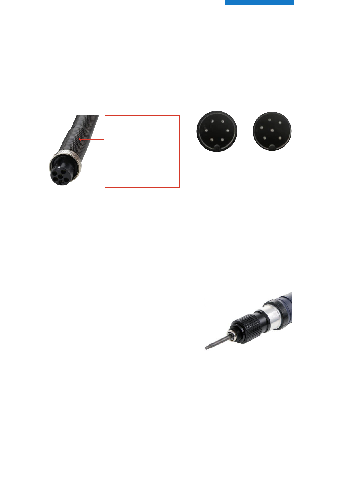
Ensure that the controller’s power is switch is in the ‘off’ position. Connect the 6-pin tool cable to the
screwdriver. The cable has a spring guard at the one end for added protection and durability. Plug this
end of the cable into the tool. The connector is designed to be a tight fit – seat the connector firmly into the
receptacle and tighten the nut securely by hand. Attach the other end of the cable to the controller in the
same manner. Plug the supplied power cable cord from the controller into a suitable, properly grounded
AC receptacle.
Always turn off controller power and wait 3 seconds before connecting or disconnecting the screwdriver
cable. Do not connect/disconnect the screwdriver with the power supply turned on.
3.3 BEFORE YOU TURN ON THE CONTROLLER
Insert the desired screwdriver installation equipment, into the quick change holder of the driver.
For tools with ¼” hex bit holders, insert the desired installation equipment by pushing (or pulling, depen-
ding on the model) the outer sleeve of the bit holder to release the retainer. Insert an appropriate power
installation equipment, release the sleeve and ensure that the installation equipment is properly locked in
place by pulling back and forth on the installation equipment.
Screwdriver end of cable
includes spring guard for
added durability
Push cable connector firmly
into receptacle and secure
retaining nut hand tight.
Do not overtighten.
32VDC 6-pin
035/E/A – 32V /
CESL8-32V
Series Tool
Connector
40VDC 6-pin
035/E/A – 40V /
CESL8-40V
Series Tool
Connector
Make sure that the tool’s start mechanism (lever, trigger, or
push start) is not engaged to prevent the tool from acciden-
tally starting when turning on the controller’s power switch.
Turn the controller’s main power switch on. Select the desi-
red speed (Hi/Lo) of the screwdriver via the speed switch on
the controller.
If you are using a 40V controller (035/E/A/40V) make sure that
the output is set to match the screwdriver. The covered out-
put voltage select switch for this is situated on the back face
of the controller.

8
3.4 OPERATING THE SCREWDRIVER
All models have a forward/reverse switch.
Grip the screwdriver so that the index finger is comfortably over the trig-
ger (Start Lever) mechanism and the thumb can be used to change the
position of the fwd/rev switch if required. Hold securely to prevent the
screwdriver from rotating in the hand during use.
Familiarize yourself with the operation of the tool by free running the tool
before use at higher torque values.
Align the driver installation equipment properly with the head of the
fastener. Keeping the driver in line with the fastener, activate and hold
the start mechanism (lever, trigger, or push). The screwdriver will ins-
tall the fastener (FWD). When the pre-set torque is reached, the clutch
will activate and the tool will shut off. Once the tool shuts off, release
the start mechanism to reset. To stop the screwdriver before fastening is
complete, release the start mechanism.
To remove a fastener, change the FWD/REV switch to the REV position.
Press the start mechanism to run the screwdriver in reverse (CCW).
Do not switch from forward to reverse (or reverse to forward) while the
motor is running. A protective circuit will stop the tool if it is inadvertently
switched while running – if this happens, the trigger must be released and
reactivated to continue operation.
3.5 SETTING THE TORQUE
An external torque adjustment nut located at the nose of the screwdriver is used to set the output torque
of the screwdriver. A reference scale (0-8) is available as a guide – this scale is for reference only and
does not indicate actual torque values. Rotate the torque nut clockwise to increase torque output, ccw
to decrease torque output. Make the torque adjustment through a series of gradual increases, starting
below the desired torque level. We recommend the use of an appropriate torque tester and static joint
testing after installation to verify proper torque settings. Once the torque is set, remove the housing nut
and cover the torque adjustment nut with the included torque lock sleeve. This will help avoid accidental
torque adjustments. The torque output of the screwdriver should be verified on a regular basis. Frequency
of verification will depend on the customer’s specific application and quality control requirements. During
the initial screwdriver break-in period, output torque may decay somewhat as the mechanical components
wear in.
9
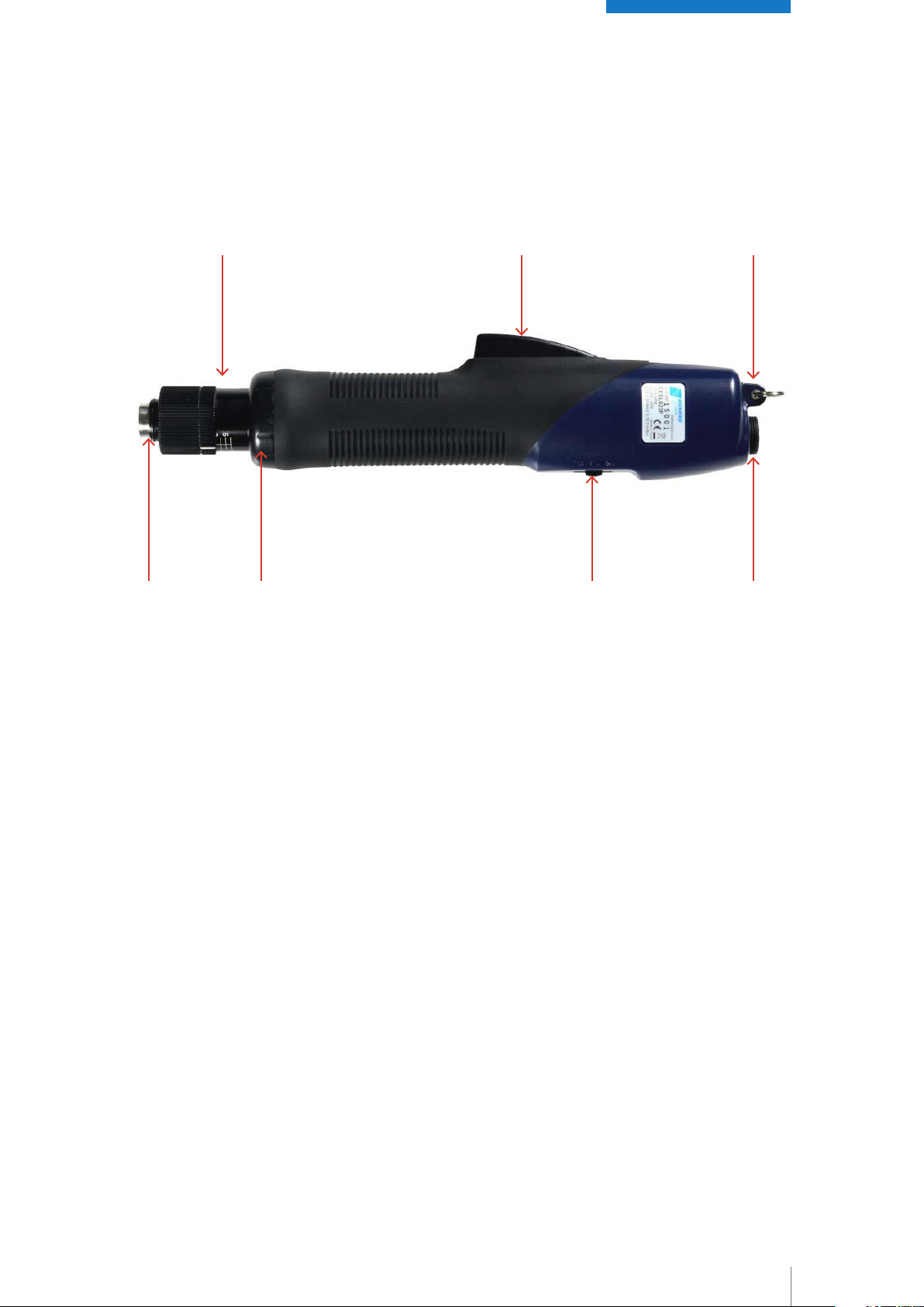
3.6 GENERAL SCREWDRIVER LAYOUT
1) 2) 3)
4) 5) 6) 7)
1) Torque Adjusting Nut
Turn CW to increase torque setting, CCW to decrease torque output. Higher values on scale indicate a
higher torque setting. Please note – numbers (1-8) on the scale are for
reference only and are not actual torque values.
2) Start Lever
Press to start the screwdriver and hold until the driver shuts off (CW tightening).
3) Suspension Bail
Use the bail to hang the screwdriver from a tool balancer.
4) Bit Holder
Retract sleeve to Insert/remove bits/tool is inserted, release the sleeve, and pull back and forth on the bit/
tool to verify retention
5) Housing Nut
Remove the housing nut to install a torque locking sleeve. The lock sleeve covers the torque adjusting nut
to deter unintentional changes to the adjustment
6) FWD/REV Switch
Select the desired direction of rotation for the screwdriver - FWD (CW) or REV (CCW) Some models also
have an OFF position.
7) Tool Cable Connection
Align the pins of the cable with the socket and push the cable’s connector firmly into place. Carefully hand
tighten the securing ring – do not overtighten.

10
3.7 MODEL NUMBERS AND SPECIFICATIONS
3.7.1 32VDC CESL8 SCREWDRIVERS
035/E/A/0.3-32V / 0.29 – 1,86Nm
Brushless Electric Screwdriver 32V DC.
(2.6 - 16.5 IN/ LBS) 0.29 -1.86 Nm range, 700 / 1.000 rpm
035/E/A1.0 - 32V / 0,98 - 2,94 Nm
Brushless Electric Screwdriver 32V DC.
(8.7 – 26.0 IN/ LBS) 0.98 - 2.94 Nm range, 900 / 1.200 rpm
3.7.2 40VDC CESL8 SCREWDRIVERS
035/E/A2.0 - 40V / 2,00 - 6,00 Nm
Brushless Electric Screwdriver 40V DC.
(18 - 53 IN/ LBS) 2.0 -6.0 Nm range, 750 / 1.000 rpm
035/E/A4.0 - 40V / 4,00 - 12,00 Nm
Brushless Electric Screwdriver 40V DC.
(36 – 106 IN/ LBS) 4.0 - 12.0 Nm range, 680 / 880 rpm
035/E/A8.0 - 40V / 8,00 - 25,00 Nm
Brushless Electric Screwdriver 40V DC
(71 – 221 IN/ LBS) 8.0 - 25.0 Nm range, 250 / 350 rpm
3.7.3 POWER SUPPLY/CONTROLLER SPECIFICA
TIONS
One controller (order separately) is required per driver.
CE/RoHS/ETL Approved.
Model 035/E/32V / BECT832N-SSO is an optional count/verify controller for the 035/E/A 32VDC CESL8
series screwdrivers.
Please refer to the separate 035/E/32V / BECT832N-SSO Manual for further details and functionality.
035/E/40V / BECT940-SSO is an optional count / verify controllers for the 035/E/A 40VDC CESL8 series
screwdrivers. Please refer to the separate 035/E/40V / BECT840-SSO Manual for further details and fun-
ctionality.
40V and 32V Controllers
035/E/40V
Brushless power supply 40V DC – Controller – single output- HI / LO Speed – Count Verify.
035/E/32V
Brushless power supply 32V DC – Controller – single output- HI / LO Speed – Count Verify.

11
3.8 SLOW START / OUTPUT SIGNAL MODULES
Optional modules are available to add slow start and I/O functionality to the standard 035/E/A / CESL8 tool
and controller. These modules plug in-line between the controller and the screwdriver. All modules offer
adjustable slow start (0-9.9sec, 30~100% of full speed). Some models include input signal capability to
provide further screwdriver control.
Please contact us or visit our website for further details on available modules and their features.
3.9 ACCESSORIES AND PARTS
Bossard offers various accessories for use with the screwdrivers.
Please contact us or visit our website for further details on available accessories.
If you require a parts drawing or replacement spare parts for your Delta Regis product, please call us or
send an
e-mail request to bossard@bossard.com
3.10 SERVICE
The controllers are not user serviceable. Any repairs must be performed by a Delta Regis authorized
service centre. Please consult Bossard for further information. Repairs to the screwdrivers must be per-
formed by trained personnel, knowledgeable and qualified in the repair of DC electric screwdrivers. Use
only genuine parts when servicing these products.
Do not attempt to modify the tools or controllers.
3.11 WARRANTY
The 035/E/A / CESL8 Series Tools and Controllers are warranted for one year from the date of purchase
against defects in material and workmanship. In addition, the brushless motor in the 035/E/A / CESL8
Series Screwdrivers is warranted for three years from the date of purchase against defects in material or
workmanship.
This warranty does not cover damage due to transportation, abuse, misuse, or improper service. Our sole
remedy is to repair or replace (at our discretion) any unit found to be defective due to defects in material or
workmanship. It is the responsibility of the user to return any product thought to be
defective, freight prepaid, to our warehouse for inspection and evaluation.
There is no warranty or merchantability or fitness of purpose. In no event will Bossard / Delta Regis Tools,
Inc. be liable for business interruptions, loss of profits, harm, injury, damage, personal injury, cost of delay,
or any other special, indirect, incidental, or consequential losses, costs, or damages.

12
4.0 SCREWDRIVER CONTROLLER
035/E40V & 035/E32V / BECT940 / 832N-SSO Screwdriver
Controller – Operation Manual
CAUTION – Please read, understand, and follow
all operating and safety instructions in this
manual before using the035/40V & 035/E32V /
BECT832N / 940-SSO controller.
These controllers are designed for use exclusively
with the following Delta Regis Brushless Electric
Screwdrivers:
035/E32V / BECT832N-SSO:
035/E/A 32VDC / CESL8 series screwdrivers
035/E40V / BECT940-SSO: 035/E/A 32VDC and
40VDC / CESL8 series screwdrivers
Do not attempt to use these controllers with any
other tools
1. Please read and understand the operation manual and follow all safety and operation instructions
2. Use these products in a suitable dry, indoor location. Do not use tools and controllers in damp, wet or
high temperature environments. Do not use in the presence of flammable liquids or gases.
3. Ensure that the controller has proper ventilation. Do not expose the tools and controllers to areas
subject to airborne contaminants (eg. dust, metal filings).
4. Use only a properly grounded electrical outlet of the correct supply voltage to power the screwdriver
controller.
5. Ensure that the supply outlet is overload protected and of sufficient amperage capacity.
6. Use only the correct plug for the controller and outlet. Hold the plug of the power cord when connecting
or disconnecting. Do not pull on the cable.
7. Do not expose the cable, tool or controller to oil, chemicals, or heat. Ensure that the cable is routed and
used in such a manner as to not be subject to sharp objects that may abrade or cut the cable.
8. Locate the controller in a suitable, safe location on a steady surface. Do not place in a high location
where there may be a risk of it falling. Secure the controller in position to prevent possible movement
caused by pulling on the power or tool cables.
WARNING
Failure to understand and follow proper installation guidelines,
safety requirements, and operating instructions may result
in malfunction, component damage, property damage, shock
hazard, fire hazard, injury or death.
4.1 IMPORTANT INSTALLATION & SAFETY

13
9. Do not cover the controller or stack any objects on top of or near the controller. Ensure that adequate
clearance and ventilation is provided around the perimeter of the controller.
10. Specific models of 035/E/A / CESL8 series controller are designed for use with 035/E/A series
screwdrivers as specified on the following pages. Use of controller (or screwdriver) with any other
screwdriver (or controller) may result in malfunction, damage, or injury.
11. In the event that the controller is overloaded beyond the maximum current rating, an internal fuse will
disrupt power. Should the controller stop functioning, or exhibit abnormal or intermittent operation,
please discontinue use immediately and send the controller to an authorized service centre for
troubleshooting and repair.
12. Excessive duty cycle will cause the tool and/or controller to overheat. If this occurs, discontinue use
until cooled down and reduce cycle rate. As a general rule, do not exceed 10-15 screws/minute, one 8
hour shift per day.
13. The 035/E/A / CESL8 series screwdrivers incorporate a protection circuit which stops the electric
screwdriver if the tool is switched from forward to reverse while running. Should this happen, the
operator must release the tool trigger and restart the fastening cycle.
14. Power the controller off and wait for 3 seconds before connecting/disconnecting the screwdriver tool
cable to/from the controller.
15. Turn the main power switch off when the controller is not being used. Unplug the controller if it is not
being used on a regular basis.
16. Do not attempt to disassemble or repair the screwdriver or controller. Repairs should only be per-
formed by qualified technicians properly trained in the safe operation, troubleshooting, and repair of
these devices. Please consult Bossard for the location of the nearest service depot.
17. Use only the factory specified Delta Regis brand replacement parts and accessories with these tools
and controllers.
18. Any damage to the tool and/or controller resulting from misuse, abuse, or failure to follow these
guidelines will void the limited warranty period.
Grounding – This controller (and AC power cord) is equipped with a 3-prong electrical
receptacle/plug with ground pin. The controller must be connected to a properly grounded AC elec-
trical outlet. Do not attempt to use this controller without a properly functioning ground connection.
Never connect a live circuit to the ground pin or internal yellow-green ground wire.
4.2 SPECIFICATIONS
Model Number 035/E32V / BECT832N-SSO;
035/E40V / BECT940-SSO
Input 100-240V AC, 50/60Hz, ~6.3A
Output
40 / 32 / 24 VDC,
60W 035/E32V / BECT 832N-SSO
360W 035/E40V / BECT940-SSO
Speeds Hi / Lo (switch selectable)
Use exclusively with screwdriver models 035/E/A 32VDC / 40VDC / CESL8 series screwdrivers
Slow Start Function Selectable ON / OFF
Slow Start Time Adjustment 0 – 9.9 seconds
Slow Start Speed Adjustment ~ 30 – 100% of rated speed

14
Count Method (selectable) Count up total / count down from total
Count Setting Range (rundown) 1 – 99
Time Windows Settings
Minimum acceptable rundown time 0.00 – 9.90 seconds (0.01 sec increments)
Maximum acceptable rundown time 0.00 – 9.90 seconds (0.1 sec increments)
Aduble Alarm Settings (selectable)
"On" sounds when Good / No Good / Batch Complete
"OF" sounds when No Good
"FF" sounds when Batch Complete / No Good
"EF" sounds when Good / Batch Complete
Input Connections Remote start, remote reverse, disable tool, external confirm,
enable batch, external clear
Output Connections Rundown OK, rundown NG, batch complete
Included Accessories AC power cord, key for program lock, user manual
Dimensions (L x W x H) ca. 225 x 130 x 100 mm
Weight ca. 2.5 kg
Approvals CE / RoHS / ETL

15
4.3 GENERAL CONTROLLER OVERVIEW
Front Face of Controller
Rear Panel of Controller
Screwdriver Hi/Lo Speed Selector
Program Function Key Lock
Keypad and Indicators for Programming and Status Monitoring
Main Power ON/OFF Switch
AC Input Cable Receptacle
Input / Output Connection Terminal Block
Dip Switch for Selecting Optional Functions
Dip Switch for Selecting Optional Functions
Screwdriver Cable Connector
4.4 GETTING STARTED
The 035/E40V / BECT940-SSO is designed to work with both 035/E/A 32VDC and 40VDC CESL8 brushless
screwdrivers. In order to accommodate the series of tool being used, an OUTPUT voltage must be set via a
covered selection switch on the rear face of the controller. Slightly loosen (do not remove) the two screws
securing the OUTPUT cover in place. Pivot the cover down and move the slide switch left (24-32V) for
32VDC brushless screwdrivers, or right (32-40V for 40VDC brushless screwdrivers. Reposition and tighten
the cover.
Connect the 6-pin cable of a compatible 035/E/A / CESL8 brushless screwdriver from the tool to the con-
troller. 035/E/A 40VDC CESL8 brushless tools plug directly into the controller connector. 035/E/A 32VDC
/ CESL8 brushless tools require use of an adapter cable. Ensure that the cable is installed in the proper
orientation (spring guard at tool end) and that the connectors are seated properly with the fastening rings
secured.

16
Plug the controller into a properly grounded AV outlet. Turn ON the main power switch on the back of the
controller. The audible alarm will beep, the RUN indicator LED (green) will light up, and the display panel
will show the starting batch count value. One of the three output voltage LED indicators (24/32/40V) will be
lit up, indicating the controller’s output voltage to the tool. Changing the speed selector switch from HI to
LO will toggle between the two available speeds/voltages for that series of tool.
4.5 KEYPAD AND PROGRAMMING BASICS
ON – CLEAR KEY
Pressing and holding the ON button for 5+ seconds will cause the display to go blank. In this mode the
screwdriver will function at HI/Lo speed, but there will be no other functionality (counting, slow start, etc.).
Pressing ON from this mode will restore the display and added functionality. Other uses of ON/CLEAR are
explained where required throughout this manual.
SELECT KEY
The SELECT key is used primarily for entering the program editing mode and
cycling through the available program settings.
Other uses of SELECT are explained where required throughout this manual.
UP/DOWN ARROW KEYS
The UP and DOWN arrow keys are primarily used to make adjustments to
numeric values when in the program edit mode. Pressing both keys simultaneously
cycles through the available sound options for the controller.
Other uses of the ARROW keys are explained where required throughout this
manual.
SOFTWARE KEYPAD LOCK
Pressing SELECT + UP ARROW together will toggle the software keypad lock
on/off. This lock limits functionality of the keypad (eg – no entering program
edit mode). ‘LC’ will momentarily display, indicating locked. ‘Un’ will display indicating
unlocked.

17
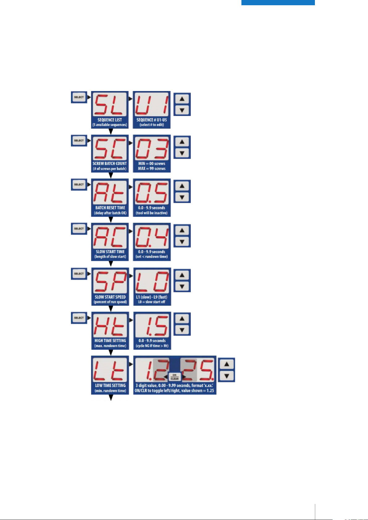
4.6 PROGRAM OPTIONS AND EDITING
4.6.1 SEQUENCE NUMBER SL
There are 5 programmable screw fastening sequences (SL = ‘U1’ to ‘U5’) available. In many cases, only the
first sequence (U1) will be needed. If the screwdriver is used to install a batch of fasteners with varying
requirements, multiple sequences may be necessary. For example, if an assembly requires the installation
of 4 screws, where 3 screws are short, and 1 screw is long, the controller can be programmed with 2
unique sequences - a sequence for the short screws and one for the long screws. This would allow different
time windows to be set-up for the two difference screw lengths. Each sequence must be programmed
separately, and numbered in the order that the screws will be installed (starting with sequence U1). In this
example, if the 3 short screws are to be installed first, enter the program for sequence ‘U1’ with a batch
quantity of 3 and time parameters for the short screw. Then repeat the program steps for sequence ‘U2’
with a batch quantity of 1 and the time parameters for the long screw. Finally, program sequence ‘U3’ with
a batch quantity of ‘00’ to signify that there are no further fasteners to install.
(For multiple sequences, refer also to info on setting dip switch #6 later on in this manual)
4.6.2 BATCH COUNT SETTING SC
Enter the desired number of fasteners to be installed per batch. Depending on the setting of DIP switch #1,
the display will either count down from the total batch value entered, or count up to the total batch value.
The count will only increment (and indicate ‘GOOD’ rundown) if the rundown cycle falls within the limits set
by the min and max rundown time settings (see below). When all fasteners in the batch have been installed,
the controller will indicate that the batch complete and the count will reset for the next cycle. If, after a good
rundown, the operator runs the screwdriver in reverse, the batch count value will decrement by a count of
one (based on the assumption that the operator is removing the last installed fastener). The batch count
can be reset to begin a new batch by pressing ON/CLEAR key.
4.6.3 END OF BATCH RESET TIME RT
When a rundown batch is completed, the controller provides a visual indication (count = ‘00’) and audible
indication (depending on audible settings) that the batch is complete, followed by a reset of the display
count for the beginning of the next batch. The END OF BATCH RESET TIME value determines how long
these indicators will stay on before the batch count resets. Please note that the screwdriver cannot be
operated during this reset time period.
4.6.4 SLOW START TIME (RC) and SLOW START SPEED
(SP)
Please refer to the section entitled ‘Screwdriver Speed Adjustments’ for further information on the Slow
Start function.

18
4.6.5 MAXIMUM AND MINIMUM RUNDOWN TIME
SETTINGS HT, LT
The controller determines whether a fastener rundown is deemed GOOD (OK) or NO GOOD (NG) by compa-
ring the actual time taken for the rundown cycle to a time window programmed by the user. For example,
a cross threaded screw will cause the screwdriver to shut-off too early (before min time) and the stripped
screw will cause the driver to run too long (beyond max time)
NO GOOD (NG)
Cycle Start MIN Time
If the fastening cycle completes (clutch trips) within the programmed time window, the rundown cycle will be accepted as GOOD (OK)
and the batch count will increment.
MAX Time
GOOD (OK) NO GOOD (NG)
Time (seconds)
4.6.6 RECONFIRM TIME LL
If the assembly process requires that the operator has the ability to ‘double-hit’ the fastener (release and
retrigger the screwdriver on a fastener that has just been installed), a reconfirm time can be programmed
into the control. During this time period (which immediately follows the completion of the rundown), the
operator is able to re-trigger the tool without causing a No Good (NG) error signal to be generated. Slow
start time (RC) must be set to a value of ‘0.0’ for this function to be available, so that the tool has full power
to run the re-hit cycle.
19
4.6.7 DETAILED PROGRAM EDITING
Notes and Guidelines:
Programming Mode Locks
To view or edit the sequences, the KEY
LOCK must be unlocked and the software
lock (toggled by pressing SELECT + UP
simultaneously) must also be unlocked
(Un). If the lock is on when you attempt to
enter programming an LC will be displayed.
(Rt) Batch Reset Time
At batch completion, the scredriver will not
operate fot the length of the batch reset
time setting.
(RC) Slow Start Time
The slow start time must be less than the
time required to install the screw. The tool
must switch to full speed before the clutch
activates for shut-off.
(SP) Slow Start Speed
Slow start speed is adjustable in steps from
lowest (L1 ~ 30% of full spd) to highest (L9
~ 85% of full spd). L0 equals 100% of run
speed or slow start off.
(Ht) High Time and (Lt) Low Time
The Ht and Lt settings establish a time
window for OK/NG evaluation of a fastener
rundown. Low Time (Lt) must be set to a
value lower than High Time (Ht) during
programming or an error (Er) will occur.
Ht value must be > Lt.
Adjust value
UP / DOWN
Adjust value
UP / DOWN
Adjust value
UP / DOWN
Adjust value
UP / DOWN
Adjust value
UP / DOWN
Adjust value
UP / DOWN
START -EDIT
PROGRAM
Press and hold SELECT
for about 5 seconds
until 'SL' displays.
Release to view pro-
grammed value
Press until
'SC' displays.
Release to
view value.
Press until
'Rt' displays.
Release to
view value.
Press until
'RC' displays.
Release to
view value.
Press until
'SP' displays.
Release to
view value.
Press until
'Ht' displays.
Release to
view value.
continued on next page ...

20
EXIT PROGRAM MODE
continued from previous page ...
Adjust value
UP / DOWN
Adjust value
UP / DOWN
Adjust value
UP / DOWN
Adjust value
UP / DOWN
Press until
'LL' displays.
Release to
view value.
Press until
'nS' displays.
Release to
view value.
Press until
'rt' displays.
Release to
view value.
Press until
'rr' displays.
Release to
view value.
Press until
'rS' displays.
Release to
view value.
Toggle value
The final option displayed will
be dependent on the settings
of 'Rc', 'LL' and 'rt'. Once the
final value is adjusted, press
SELECT to return to normal
operation.
(LL) Re-Hit Screw Time
Programming of the (LL) value is only avai-
lable if Slow Start Time (RC) is set to 0.0
(slow start off). The re-hit function can't be
used in conjunction with slow start.
(rt) Auto-Reverse Time
Entering a value greater than 0.00 for
auto-reverse time will cause the driver to
reverse after the clutch trips for the preset
amount of time. 'LL' must be set to 0.00 for
the 'rt' function to be available.
(rr) and (rS) Reverse / Pause / Tighten
Entering a value greater than 0.00 for 'rr'
will start the cycle with a timed reverse
('rr' value), then forward until the clutch
activates.
Note:
- FWD/REV switch must be in REV position
for the function to work.
- 'LL' and 'rt' must equal 0.00 for the 'rr' to
be available.
(nS) Disable Screwdriver on 'NG'
If 'nS' is set to y (yes), the screwdriver will be disabled after a
no good (NG) rundown. The operator must confirm by pressing
the SELECT key, or an external confirm signal must be input
through the I/O. (applies to forward cw rotation only).
3 Digit Time Values
The values for Lt, LL, rt, rr and rS are 3-digit time
values in seconds with a format of x.xx.
To view/edit the entered value, toggle left and right
using the 'ON/CLEAR' button. The position of the
decimal point on the screen indicates whether you are
viewing the 'ones' and 'tenths' digit, or the 'tenths' and
'hundredths' digits respectively.
Note that the 'tenths' digit appears on both screens.
This manual suits for next models
3
Table of contents
Popular Power Tools manuals by other brands


ERBA
ERBA 20061 instruction manual

SmartHeat
SmartHeat Metcal SP440 System user's guide

SCHUNK
SCHUNK TANDEM KSF plus Series Assembly and operating manual

Dow
Dow GREAT STUFF PRO 13 Installation information

Simco
Simco COBRA user manual

Chicago Electric
Chicago Electric 61687 Operation manual and safety instructions