SmartHeat Metcal SP440 User manual

Artisan Technology Group is your source for quality
new and certied-used/pre-owned equipment
• FAST SHIPPING AND
DELIVERY
• TENS OF THOUSANDS OF
IN-STOCK ITEMS
• EQUIPMENT DEMOS
• HUNDREDS OF
MANUFACTURERS
SUPPORTED
• LEASING/MONTHLY
RENTALS
• ITAR CERTIFIED
SECURE ASSET SOLUTIONS
SERVICE CENTER REPAIRS
Experienced engineers and technicians on staff
at our full-service, in-house repair center
WE BUY USED EQUIPMENT
Sell your excess, underutilized, and idle used equipment
We also offer credit for buy-backs and trade-ins
www.artisantg.com/WeBuyEquipment
REMOTE INSPECTION
Remotely inspect equipment before purchasing with
our interactive website at www.instraview.com
LOOKING FOR MORE INFORMATION?
Visit us on the web at www.artisantg.com for more
information on price quotations, drivers, technical
specications, manuals, and documentation
Contact us: (888) 88-SOURCE | sales@artisantg.com | www.artisantg.com
SM
View
Instra

Metcal is an OK International Company
MANUEL D’UTILISATION METCAL SP440
MANUALE DI ISTRUZIONI PER L’ USO DI METCAL SP440
METCAL SP440 SYSTEM USER GUIDE
BENUTZERHANDBUCH FÜR METCAL SP440 SYSTEM
Copyright © 1996, Metcal Inc. All Rights Reserved. 7026-0580 Rev A
Cover.qxd 3/30/99 9:11 AM Page 2

SYSTEM ASSEMBLY....................................................1
TIME-OUT FEATURE ....................................................1
AUTO-OFF FEATURE....................................................2
NO CALIBRATION REQUIRED.........................................2
CHOOSING THE CORRECT DESOLDER CARTRIDGE ...........3
CHOOSING THE CORRECT GEOMETRY ............................3
CHOOSING THE CORRECT TEMPERATURE (SERIES) ........3
INSERTING TIP CARTRIDGES........................................3
TURNING THE UNIT ON.................................................4
REPLACING DESOLDERING TIP CARTRIDGES..................4
PROPER DESOLDERING TECHNIQUE................................4
DESOLDER SYSTEM CARE
REPLACING THE LINER AND FILTER.........................5
REPLACING THE COIL ASSEMBLY ...........................5
REPLACING THE SEAL............................................6
REPLACING THE VALVE BODY ASSEMBLY...............6
TROUBLESHOOTING GUIDE...........................................7
SYSTEM SPECIFICATIONS ...........................................8
WARRANTY/RETURN PROCEDURE......................................8
METCAL SP440 SYSTEM USER GUIDE
TECHNICAL AND CUSTOMER SERVICES: HERE TO HELP YOU
If you have difficulty setting up your system, diagnosing problems, or replacing any part,
please give your local Metcal representative a call.
In addition, we have data sheets available on tip cartridges and accessories for this and other
Metcal Systems. Please make sure you have returned the product card that shipped with this
system so that we can send you these data sheets, as well as product updates and our
technical support newsletter. If you have lost your card, or if you are not the original user of
this system, please give us a call so that we can register you.
Copyright © 1996, Metcal Inc. All Rights Reserved. 7026-0220
United Kingdom & European Headquarters
Eagle Close, Chandlers Ford
Hampshire, SO53 4NF
England
Tel: +44 (0) 2380 489 000
Fax: +44 (0) 2380 489 109
Internet: www.metcal.com
AN OK INTERNATIONAL COMPANY
CE & TUV approved

1Copyright © 1996, Metcal Inc. All Rights Reserved. 7026-0220 Rev 2
SYSTEM ASSEMBLY
The Metcal SP440 Self-Contained Desolder System consists of a single port power supply,
desolder workstand with wiping sponge, and a desolder handpiece that uses replaceable tip
cartridges. (Tip cartridges are sold separately from the system.)
The power supply features a port for the desolder handpiece, an on/off switch, and a green
“Power On” indicator light (this light turns amber in “Auto-Off” or “Time Out” mode).
The desolder handpiece is the heart of the desolder system. The tool consists of the main
handgrip and vacuum trigger, the coil assembly, the solder collection chamber, and the
valve body assembly. The paper solder collection filter and main fume filter are located
inside the solder collection chamber in the handpiece. The vacuum hose and the electrical
cord connect the handpiece to the power supply. Both cords are burn resistant and ESD-
safe.
To attach the handpiece:
1. Insert the cord connector into the power supply
port on the front of the unit.
2. Turn the connector 1/4 turn clockwise, or until it
locks.
The inline filter is located in the back of the system,
connecting to the vacuum hose between the
handpiece and the power supply. Remove the plug before
connecting the inline filter to the vacuum hose and power
supply.
To attach the desolder handpiece vacuum line and inline
filter:
1. Make sure the power cord is NOT connected to the unit.
2. Attach the vacuum hose to the inline filter on the back of
the power supply.
3. Attach the power cord to the receptacle on the back
underside of the power supply.
Plug the power cord into a grounded wall socket of the appropriately rated input line
voltage.
Note: The DSG2 desolder handpiece IS not compatible with the SP200. Similarly, the HC1
solder handpiece and HC2 solder handpiece cannot be used with the SP440.
TIME-OUT FEATURE
One of the most common and needless causes of shortened tip cartridge life is leaving the
power supply on during breaks or unattended for long periods of time. This is one of the
primary reasons Metcal advocates shutting your system off when not in use. However, we
realize that remembering to turn your system off can be the furthest thing from your mind.
So, the SP440 has an automatic Time-Out feature. This feature works by shutting off the
INLINE FILTER
VACUUM HOSE
INLINE FILTER PORT
POWER CORD PLUG

2
AUTO-OFF FEATURE
The SP440 power supply has a built-in Auto-Off feature. In the event that there is an
interruption in the ground circuit path, the Auto-Off feature will shut off the power supply.
Just as in the “Time Out” feature, the green light will turn amber.
Conditions that will cause the Auto-Off feature to trigger are:
• Coil assembly not installed in handpiece
• No handpiece connected to power supply
• Open circuit caused by a bad coil assembly or handpiece
• Short circuit caused by a bad coil assembly or handpiece
To reset the system, first correct the fault condition, then push the on/off switch “off”,
then back “on”. (If the problem is not fixed first, the Auto-Off feature will shut off the
power supply port after reset, and the power light will continue to be amber rather than
green)
NO CALIBRATION REQUIRED
METCAL®SMARTHEAT®SOLDERING, DESOLDERING, AND REWORK SYSTEMS DO NOT
REQUIRE SYSTEM CALIBRATION FOR TEMPERATURE.
A Metcal System is comprised of a power supply with handpiece/cord assembly and a tip
cartridge. Each cartridge is equipped with a self-regulating heater, which senses its own
temperature and tightly maintains its pre-set idle temperature for the life of the cartridge.
The heater temperature is set by the metallurgical properties of the heater material. It
cannot be adjusted, and does not require any adjustment.
The power supply with handpiece/cord assembly does not contain the heater or any tip
temperature sensors, but simply provides the current to the heater. Any expected power
supply variability does not adversely affect its ability to maintain the necessary current to
the heater. There are no adjustments to be made.
The term calibration implies that because of inherent shift over time in a system, periodic
adjustment must be made to maintain performance. Calibration schedules are normally
based on anticipating when an out-of-tolerance condition will occur and calibrating or
adjusting prior to this event. In a Metcal System, there is nothing to adjust, so the system
cannot be changed from its initial state. Therefore, NO CALIBRATION is required.
Those companies or individuals requiring periodic verification of system performance should
call their local Metcal representative for a copy of Metcal’s ISO 9000 Tech Note.
Call your local Metcal Technical Support office with any questions. In addition, a signed
letter of “No Calibration Required” is also available.
Copyright © 1996, Metcal Inc. All Rights Reserved. 7026-0220 Rev 2
3Copyright © 1996, Metcal Inc. All Rights Reserved. 7026-0220 Rev 2
TOO LARGE
DP-VP2 Vacuum pump for SP440-21
DP-DSG2 Desolder Tool assembly, pencil grip
DP-CA2 Coil assembly
DP-CC Solder Collection chamber
DP-FIL Filter Pack:
1 In-line filter, polypropylene
1 Cleaning brush
12 Flux filters - white
24 Paper filters for the collection
chamber
CHOOSING THE CORRECT DESOLDER CARTRIDGE
Proper tip cartridge selection is important for getting the best results. Choosing the right
tip cartridge will maximize your performance at the lowest possible temperature. Since
changing tip cartridges is so quick and easy, there is no need to compromise.
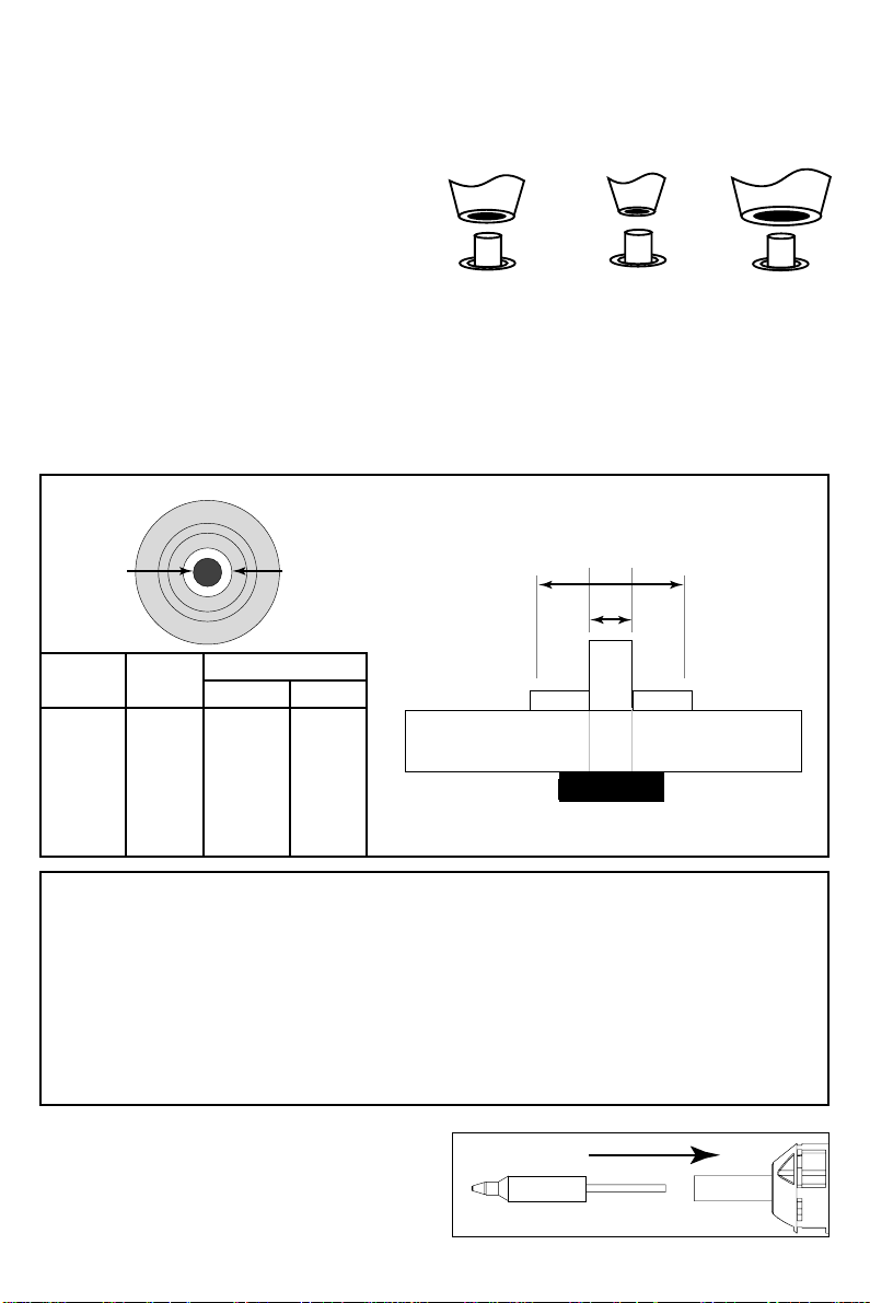
CHOOSING THE CORRECT GEOMETRY
Select a tip cartridge with an inside
diameter larger than the lead diameter,
and an outside diameter that is
approximately the same size as the pad.
CHOOSING THE CORRECT TEMPERATURE (SERIES)
The SP440 features high durability SDC desolder cartridges, designed for high heat transfer,
making desoldering on multi-layer boards much easier. Desolder cartridges are available in two
temperature ranges (600 and 700 Series). A typical board usually requires a 700 Series tip
cartridge. Try a 600 Series tip cartridge first for thermally sensitive components or small single-
INSERTING TIP CARTRIDGES
Insert a desolder tip cartridge into the
desolder handpiece by pushing it in until it
Inside
Diameter
(A)
0.6mm
0.8mm
1.0mm
Outside
Diameter
(B)
1.4mm
1.5mm
1.8mm
600
Series
SDC-602
SDC-603
SDC-604
700
Series
SDC-702
SDC-703
SDC-704
PART NUMBER
L
E
A
D
B
A
ACCESSORIES

4
TURNING THE UNIT ON
To turn the unit on, press the front part of the switch down. The green LED will light up. If
it does not, or if the light is amber, consult the troubleshooting guide.
REPLACING DESOLDERING TIP CARTRIDGES
1. Turn the system off. Be sure the green LED light is off before proceeding.
CAUTION: THE TIP CARTRIDGE MAY BE HOT!
2. Pull out the cartridge using the Tip Cartridge Removal Pad. A Cartridge Pad should be
attached to your handpiece cord. If not, contact your supervisor, check your company's
tool crib, or call Metcal Customer Service. DO NOT USE METAL TOOLS (PLIERS, ETC) TO
REMOVE CARTRIDGES. METAL TOOLS CAN DAMAGE THE CARTRIDGE OR COIL ASSEMBLY!
3. Push a new tip cartridge into the handpiece.
4. Turn the unit on. The new tip cartridge will heat up to temperature in less than 45
seconds.
PROPER DESOLDERING TECHNIQUE
1. Choose the correct tip cartridge for the job. Too small a tip cartridge, and you will not
get an efficient vacuum seal. If your tip cartridge is too large, overextending the pad,
you could damage the board.
2. If the board has been conformal coated, you may or may not need to remove this
coating. Usually, you can desolder through the coating. IF YOU DESOLDER THROUGH
CONFORMAL COATING, CLEAN THE INSIDE OF THE TIP FREQUENTLY WITH A TIP
CLEANER AS THESE COATINGS CAN HARDEN AND CRYSTALLIZE ON THE INSIDE OF THE
TIP, CREATING A BLOCKAGE. Usually when working with conformal coated boards, you
need only score the conformal coating on the top side along the top fillet so the solder
is allowed to be pulled through from one side and out the other.
3. Flux will minimize dwell time and aid in heat transfer, but will require more frequent
replacement of your fume filter.
4. Whenever possible, work with the board in an upright or angled (not flat) position so
you can see the distance from the tip cartridge to the pad The tip cartridge should be
perpendicular to the board, allowing sufficient heat transfer and vacuum to develop.
5. Contact the fillet. As you wait, the fillet will melt and the solder will wet the tip. This is
your vacuum seal. Now move the tip closer to the pad.
6. Move the lead back and forth with the tip. This will aid heat transfer.
7. Depress the trigger. One long pull while moving the lead will typically be sufficient. A
short burst may not remove all the solder and may result in a lead that is resweated to
the board.
8. Look at the work. If the hole is still filled with solder, don't try to immediately desolder
it again. Once any solder has been removed, you must go back and resolder. Air in the
through-hole acts as an insulator and will not allow heat transfer through to the other
side.
Copyright © 1996, Metcal Inc. All Rights Reserved. 7026-0220 Rev 2
Copyright © 1996, Metcal Inc. All Rights Reserved. 7026-0220 Rev 2
5
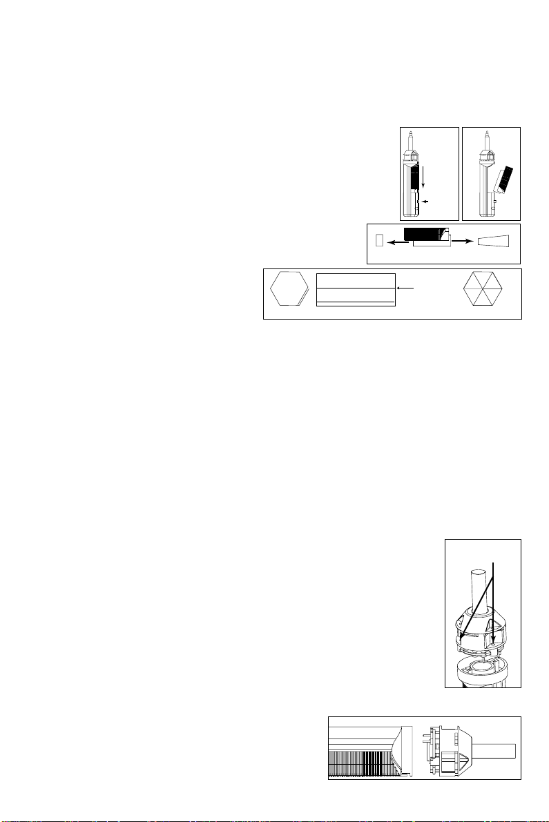
REPLACING THE LINER AND FILTER
The power supply does not need to be turned off to replace the liner and filter. However, as
a safety measure, you may want to turn off the desolder tool when changing the solder
collection and main fume filters. To ensure proper vacuum, change the filters whenever the
vacuum seems weak. NEVER USE THE DESOLDER TOOL WITHOUT A SOLDER COLLECTION
AND FUME FILTER! DOING SO CAN CAUSE FAILURE OF THE VALVE BODY AND VACUUM
1. Hold the tool with the tip pointing up.
2. Pull the collection chamber down until the grey latch pops out.
3. Pull the collection chamber out.
4. Pull the liner out. Replace if full.
5. Remove the filter. Replace if heavily discolored.
6. To replace the liner, carefully fold the
paper liner, making sure the perforated
fingers at the bottom are folded over.
7. Insert the collection liner into the
chamber, making sure it is in the front (top) of the chamber (follow the etched drawing
on the outside of the chamber). Then, insert the fume filter.
8. Put the chamber back into the handpiece. Push collection chamber to the front of the
handpiece to ensure proper mating with the coil assembly seal. Press the grey latch to
lock.
REPLACING THE COIL ASSEMBLY
Replace the coil assembly when tip cartridges fail to heat.
To replace the coil assembly:
1. Turn the power off to the desolder tool.
2. Remove the handpiece/cord from the power supply.
3. There are three screws at the top of the coil assembly. Remove them
with the small hex head allen wrench that is included with the new coil
assembly.
4. Pull off the coil assembly by pulling it straight out.
5. Insert a new coil assembly, lining up the pins to the connectors.
6. Press in the new coil assembly, taking care not to force or bend the pins.
7. Screw down the three screws included with the new
coil assembly.
PULL
DOWN
LATCH
FILTER LINER
FRONT SIDE BACK
SCREWS
OVERLAP

6
REPLACING THE SEAL
You should check the seal periodically to make sure there are no cracks or gaps. Loss of
vacuum or repeated vacuum cycling may also be a sign of a worn seal.
To replace the seal:
1. Remove the coil assembly with a 5/64” hex wrench as described earlier.
2. Pry the seal out with a small screwdriver.
3. Insert a new seal and press in
until you feel a "click". Make
sure there is a tight fit
between the seal and plate with
no noticeable gaps by spinning
the seal. It should spin freely.
4. Replace the coil assembly.
REPLACING THE VALVE BODY ASSEMBLY
To replace the valve body assembly, turn the power off to the desolder tool. Remove the
DSG2 desolder handpiece/cord from the power supply.
1. Remove the collection chamber (see “removing the collection
chamber” if you need assistance).
2. Check the valve for solder balls that can be removed. Remove
any solder balls.
3. If they cannot be removed, the valve body must be replaced.
Remove the two screws holding the valve body in place.
4. Unclip the clips that hold the vacuum hose to the electrical
cord.
5. Pull the valve up and remove it (the vacuum hose is attached
and will come off with the valve).
6. Line up the back of the new valve body assembly with the desolder tool.
Be sure to keep the trigger spring straight.
7. Press down and screw into place.
8. Clip the new vacuum hose to the handpiece.
9. Replace the collection chamber. Push collection chamber to the front of
the handpiece to ensure proper mating with coil assembly seal. Press the
grey latch to lock it in place.
VALVE BODY
SCREWS
Copyright © 1996, Metcal Inc. All Rights Reserved. 7026-0220 Rev 2

7
TROUBLESHOOTING GUIDE
If these steps do not result in proper performance, call Metcal Technical Services.
Tip Cartridge Won’t Heat
1.Be sure the tip cartridge is pushed all the way into the handpiece.
2.Check that the handpiece connector is tightened securely to the power supply.
3.If the green LED is not lit or is amber, see the section “Power Supply Light is Amber or
Off”.
4.Try replacing the coil assembly.
POWER SUPPLY LIGHT IS AMBER OR OFF
1. If the power supply light is off, make sure the power supply cord is properly connected to
the wall outlet, that the cord is securely connected to the back of the unit, and that
there is power to the wall outlet.
2.If the power supply light is amber, and you have not used the system for more than 20
minutes, the Time-Out feature may have been tripped. To reset this feature, press the
on/off rocker switch forward and release.
3.If the light is still amber, the Auto-Off protection feature may have been tripped.
Conditions that can trigger the Auto-Off and that should be checked are:
• Loose handpiece connection to power supply
• Bad coil assembly or no coil assembly installed
• Bad handpiece
IF SYSTEM IS ON BUT VACUUM IS LOW OR NONEXISTENT
1.A full liner, fume filter, or inline filter is usually the cause of low vacuum. Check and
replace if necessary.
2.Check the vacuum hose for kinks. Straighten any kinked lines.
3.Check the desolder cartridge tip to be sure nothing is blocking the inside. If a solder ball,
hardened conformal coating or flux is trapped in the tip, clean the tip by inserting the
appropriately sized tip cleaner in the tip and pressing through.
4.Check to be sure the coil assembly seal is securely seated around the tailpipe. There
should be no gaps. If the seal is worn, you should replace it.
5. The valve body may be clogged. Check and replace if necessary.
6.Ensure that the collection chamber is properly seated against the front of the unit, so
that it makes contact with the seal.
VACUUM PUMP CYCLES ON AND OFF CONTINUOUSLY
1.Check the vacuum hose for leakage and check to be sure it is attached to the back of the
unit, and the line filter connector is tight.
2.Check the valve body assembly. Replace or clean if necessary.
3.Check and replace check valve.
Copyright © 1996, Metcal Inc. All Rights Reserved. 7026-0220 Rev 2

8
POWER SUPPLY
TIP-TO-GROUND POTENTIAL < 2 mV, true RMS, 50-500
Hz
TIP-TO-GROUND RESISTANCE < 2 ohms, DC, unit on
IDLE TEMPERATURE STABILITY± 2 °F (± 1.1 °C), still air
AMBIENT OPERATING TEMP 50 - 104 °F (10 - 40 °C)
MAX ENCLOSURE TEMP 150 °F (65 °F)
INPUT LINE VOLTAGE
SP440-11 108-132 VAC
SP440-12 90-110 VAC
SP440-21 216-264 VAC
INPUT LINE FREQUENCY 45 - 70 Hz
NOMINAL OUTPUT 50 Watts @ 72°F (22°C)
ambient
OUTPUT FREQUENCY 470 KHz
TIME OUT FEATURE After 25-30 minutes idle
time
POWER CORD (3-WIRE) 6 ft (183 cm) - 18/3 SJT
DESOLDER TOOL
VACUUM RISE TIME 25 ms to 12 inches Hg
HANDPIECE ASSY 5 ft (152 cm)
carbon loaded silicone,
shielded
DIMENSIONS
LENGTH X WIDTH X HEIGHT 8.0” x 6.0" x 7.0”
20.3 x 15.2 x 17.8 cm
WEIGHT (TOTAL UNIT) 9.0 lbs (4.1 kg)
WEIGHT (DESOLDER TOOL) 8.0 oz (227 g)
STANDARDS COMPLIANCE
MIL-STD-2000, -1686, -45743E , WS-6536D and E
ESD 105-1011 ohm/square per ASTM D257
(ESD 105-109 ohm/square where possible)
SYSTEM SPECIFICATIONS
METCAL SOLDERING & DESOLDERING SYSTEMS WARRANTY
Metcal, Inc. warrants Power Supplies against any defects in materials or workmanship for two (2)
years from the date of purchase by the original owner. The DSG2 Desolder Tool is warranted against
any defects in materials or workmanship for one (1) year from the date of purchase by the original
owner. Metcal warrants all other products except consumables against any defects in materials or
workmanship for one (1) year from the date of purchase by the original owner.
This Warranty excludes normal maintenance and shall not apply to any misused, abused, altered or
damaged items. If the product should become defective within the warranty period, Metcal, Inc., will
repair or replace it free of charge at its sole option. The replacement item(s) will be shipped, freight
prepaid, to the original purchaser.
The warranty period will start from the date of purchase. If the date of purchase cannot be
substantiated the date of manufacture will be used as the start of the warranty period.
Service After Warranty
Metcal will repair or replace (at Metcal’s sole option) a power supply that fails in normal use within
three (3) years after the expiration of the two-year warranty at the then current repair or exchange
rate. To return a failed power supply for repair or replacement, follow the steps outlined below. This
offer does not apply to any previously opened, modified, repaired, altered, misused or damaged
power supply.
Replaceable coil Assembly Warranty
Metcal warrants that the coil assembly will operate according to specifications for a minimum of
1,000 hours. A coil assembly that fails to heat for at least 1,000 hours operation will be replaced at
no charge.
Replaceable Tip Cartridge Warranty
Metcal warrants that the heater in its Tip Cartridges will operate according to specifications for the
lifetime of the plating. A Tip Cartridge that fails to heat for the lifetime of the plating will be replaced
at no charge. For replacement, follow the steps outlined below. The replacements will be shipped,
freight prepaid, to the original purchaser. This Warranty shall not apply to any misused, abused,
altered or damaged Tip Cartridges.
This warranty gives you specific legal rights, and you may also have other rights which may vary from
state to state.
Return Procedure
1. Call your appropriate Metcal office to obtain a Returned Material Authorization (RMA) number.
2. Ship materials, freight prepaid, to the appropriate Metcal office with the RMA number clearly
visible on the outside of the package.
Copyright © 1996, Metcal Inc. All Rights Reserved. 7026-0220 Rev 2

A New Force In Electronics Manufacturing
Internet: www.metcal.com
Metcal is an OK International Company
●China
Beijing Wangfujing Century Square
No. 99 Wang Fu Jing Street #A526,
Dong Cheng District, Beijing, China 100006
Tel: +86 10-6525 6698
Fax: +86 10-6525 1639
●Korea+
5 Fl, Yang Chun Bldg,
330-11 Shinjung-Dong,
Yangchun-Ku, Seoul, Korea
Tel: +82 (2) 643-8833
Fax: +82 (2) 643-5539
●Australia+
Unit 1, 8 Grex Avenue,
Minchinbury 2770, NSW, Australia
Tel: +61 (2) 9832 8052
Fax: +61 (2) 9832 8045
●France
Rue Ampere,
Z.I. Lyon Nord,
69730 Genay, France
Tel: +33 (0)4 72 08 75 75
Fax: +33 (0)4 72 08 75 70
●Italia
Strada Statale 11 - N. 28,
20010 Vittuone (Milano), Italy
Tel: +39 02 90111105
Fax: +39 02 90111147
●Japan
2F ASK Bldg., 1-24-4, Ebisu,
Shibuya-ku, Tokyo, 150-0013, Japan
Tel: +81 3 449-7451
Fax: +81 3 440-2040
●Taiwan
5th Floor, No. 79, Sec 1,
Hsin Tai Wu Road, Hsi-Chih
Taipei Hsien, Taiwan, R.O.C.
Tel: +886 (2) 698-4013
Fax: +886 (2) 698-4021
+Authorised OK Representative
Metcal reserves the right to alter design and
specification without prior notice
●OK International, Inc.
4 Executive Plaza,
Yonkers, New York 10701 USA
Tel: +1 (914) 969 6800
Fax: +1 (914) 969 6650
●USA West Coast
1530 O‘Brien Drive,
Menlo Park, CA 94025, USA
Tel: +1 (650) 325 3291
Fax: +1 (650) 325 5932
●United Kingdom
Eagle Close, Chandlers Ford
Eastleigh, Hants.
SO53 4NF, England
Tel: +44 (0) 2380 489000
Fax: +44 (0) 2380 489109
●Deutschland GmbH
Bensheimer Straße 61,
D-65428 Rüsselsheim-Königstädten,
Germany
Tel: +49 (0) 6142 9360 0
Fax: +49 (0) 6142 9360 50
United Kingdom & European Headquarters
Tel: +44 (0) 2380 489000 Fax: +44 (0) 2380 489109
Deutschland GmbH
Tel: +49 (0) 6142 9360 0 Fax: +49 (0) 6142 9360 50
France SA
Tel: +33 (0)4 72 08 75 75 Fax: +33 (0)4 72 08 75 70
Italia SPA
Tel: +39 02 90111105 Fax: +39 02 90111147
Cover.qxd 3/30/99 9:11 AM Page 1

Artisan Technology Group is your source for quality
new and certied-used/pre-owned equipment
• FAST SHIPPING AND
DELIVERY
• TENS OF THOUSANDS OF
IN-STOCK ITEMS
• EQUIPMENT DEMOS
• HUNDREDS OF
MANUFACTURERS
SUPPORTED
• LEASING/MONTHLY
RENTALS
• ITAR CERTIFIED
SECURE ASSET SOLUTIONS
SERVICE CENTER REPAIRS
Experienced engineers and technicians on staff
at our full-service, in-house repair center
WE BUY USED EQUIPMENT
Sell your excess, underutilized, and idle used equipment
We also offer credit for buy-backs and trade-ins
www.artisantg.com/WeBuyEquipment
REMOTE INSPECTION
Remotely inspect equipment before purchasing with
our interactive website at www.instraview.com
LOOKING FOR MORE INFORMATION?
Visit us on the web at www.artisantg.com for more
information on price quotations, drivers, technical
specications, manuals, and documentation
Contact us: (888) 88-SOURCE | sales@artisantg.com | www.artisantg.com
SM
View
Instra
Table of contents


