BOSSCO Country Clipper SR1215 Operation and maintenance manual

Safety Instructions & Operators Manual
®
Zero Turn Radius Mower
Congratulations for buying a Country Clipper product. Your Country Clipper Zero
Turning Radius Riding Mower was designed and built to provide long and trouble free
service. Keep in mind that it, like any other mechanical device, can be potentially
dangerous if used improperly, and hazard control and accident prevention are dependent
upon the awareness, concern, prudence, and proper training of personnel involved in the
operation, transport, maintenance, and storage of the equipment. Study this manual and
pay special attention to the important Safety Precautions on pages 3-5. Following these
instructions will help you continue to enjoy the trouble-free performance
P-12717 (2/11)

2
TABLE OF CONTENTS
I. SAFETY
Accident Patterns to Avoid------------------------------------------------------ 3
Safety Instructions and Recommendations----------------------------------3-4
Safety Interlock Systems -------------------------------------------------------- 5
II. START UP AND OPERATION
Checklist Before Operation ----------------------------------------------------- 5
Operation – Joystick ------------------------------------------------------------- 6-7
Operation – Dual Lever---------------------------------------------------------- 7-8
Mowing Recommendations ----------------------------------------------------- 9
III. MAINTENANCE
Maintenance Schedule --------------------------------------------------------- 10
Maintenance Instructions ------------------------------------------------------ 11-18
Raising and Lowering Deck for Servicing --------------------------------- 19-20
Leveling the Deck --------------------------------------------------------------- 20
Adjusting the Latch Plate------------------------------------------------------ 21
Deck Flip Jack Assembly and Operation---------------------------------- 22
Troubleshooting Checklist ---------------------------------------------------- 23-24
IV. Wiring Schematic -------------------------------------------------------------------- 25-27

3
SAFETY
ACCIDENT PATTERNS TO AVOID
I. CONTACT WITH THE ROTATING
BLADE -- This accident usually
happens when the operator is clearing
the discharge chute of grass, (especially
when the grass is wet), or when the
operator adjusts the machine without
turning it off and waiting for the blades
to completely stop.
II. PROPELLED OBJECTS -- Sticks,
rocks, wires, and other objects can be
propelled out through the discharge
chute or from under the mower housing.
Bystanders are particularly vulnerable.
III. GRASS CATCHER OR GUARD -- The
mower shall not be operated without
either the entire grass catcher or guard
in place.
IV. OVERTURNING -- This happens when
riding mowers are used on steep slopes,
embankments or hills. The operator in
these cases can come in contact with
the blades or sustain injuries during a
fall.
V. MOWER RUNNING OVER THE VICTIM
-- This usually happens when a riding
mower is driven in reverse. The
accident victims are most often young
children whom, unseen by the operator
of the mower, were in the area being
mowed.
SAFETY INSTRUCTIONS AND
RECOMMENDATIONS
1. PEOPLE WHO OPERATE, SERVICE,
OR ARE OTHERWISE ASSOCIATED
with the Country Clipper Zero Turning
Radius Mower should be trained in its
proper use and warned of its dangers.
Before operating, adjusting, or servicing
the Country Clipper Zero Turning
Radius Mower they should read and
understand this entire manual and the
engine owner’s manual.
2. AVOID CONTACT WITH MOVING
PARTS. Keep hands and feet from
under mowing deck and away from
blades at all times. Turn engine (motor)
off if you must unclog the chute.
3. AVOID HILLS AND SLOPES. Use
extreme caution when mowing up or
down slopes. NEVER mow across the
face of a slope. If a slope must be
ascended, back up the slope; drive
forward when descending. Reduce
speed and use caution to start, stop and
maneuver. To prevent loss of control on
a slope avoid sharp turns, sudden
changes in direction, and sudden stops
and starts.
4. DISENGAGE POWER TO MOWER
BEFORE BACKING UP. Do not mow
in reverse unless ABSOLUTELY
necessary and then only after turning
around and observing the entire area
behind the mower. Go slowly. Most
“running over victim” accidents occur in
reverse.
5. BEGINNING OPERATORS SHOULD
LEARN HOW TO STEER the Country
Clipper Zero Turning Radius Mower
before attempting to mow. Start with
slow engine speed and drive without the
blades engaged in an open area until
comfortable with the machine.
6. KNOW HOW TO STOP QUICKLY.
Know the location and operation of
every control, especially how the brake
and how to disengage the mower
blades.
AT COUNTRY CLIPPER, WE SHARE YOUR
DESIRE TO PROTECT YOURSELF, YOUR
FAMILY, YOUR FRIENDS AND YOUR
NEIGHBORS FROM ACCIDENTAL INJURY.
OBSERVING AND ENFORCING THE
FOLLOWING GUIDELINES WILL HELP TO
INSURE THE SAFETY OF EVERYONE.
PLEASE BE CAREFUL!

4
7. DO NOT MOVE CONTROL LEVER(S)
from forward position to reverse position
rapidly. The speed and/or direction of
travel is affected instantly by movement
of the Control Lever(s).
8. DO NOT ALLOW CHILDREN TO
OPERATE MOWER. Do not allow
others who have not had instruction to
operate mower.
9. ALWAYS TURN ENGINE OFF AND
REMOVE KEY before leaving the
mower to prevent children and
inexperienced operators from starting
the engine. Never leave the mower
unattended with engine running. Always
wait for all moving parts and all sounds
to stop before leaving operator’s seat.
10. WEAR STURDY, ROUGH-SOLED
WORK SHOES AND CLOSE-FITTING
SLACKS AND SHIRTS. Never operate
mower in bare feet, sandals or
sneakers.
11. NEVER CARRY PASSENGERS.
12. KNOW THE AREA YOU ARE TO
MOW. Watch for hidden danger such
as rocks, roots, sticks, holes, bumps,
and drop-offs, etc. Before mowing, pick
up all debris in area to be mowed.
Sharp and hard objects can be
propelled at a high speed and can act
like shrapnel. Walk through tall grass
BEFORE MOWING to make sure there
are no hidden dangers. Mow higher
than desired in tall grass to expose any
hidden objects and/or obstacles, clean
the area, and then mow to the desired
height.
13. NEVER REFUEL A MOWER
INDOORS. Allow the engine time to
cool before refueling. Unseen vapors
may be ignited by a spark. Always
clean up spilled gasoline. Never run the
engine indoors in a garage or any other
closed building. Allow engine to cool
before storing in any enclosure. The
engine exhaust and gasoline fumes are
dangerous.
14. NEVER REMOVE THE FUEL CAP or
add gasoline to a running or hot engine
that has not been allowed to cool for
several minutes after running. Always
make sure the gas cap is in place.
15. DO NOT SMOKE AROUND THE
MOWER or the gasoline storage
container. Gasoline fumes can easily
Ignite.
16. KEEP GASOLINE IN A WELL-
VENTILATED AREA away from your
living quarters and in tightly-capped
safety cans. Never store mower with
gasoline in the tank inside a building
where fumes may reach open flame or
spark.
17. DISENGAGE BLADES, STOP ENGINE
AND REMOVE IGNITION KEY before
any servicing. Be sure all moving parts
and all sounds have stopped. Let
engine cool and disconnect the spark
plugs so the engine cannot start by
accident. A SLIGHT ROTATION OF
THE BLADES COULD START THE
ENGINE.
18. KEEP ALL NUTS, BOLTS, AND
SCREWS TIGHT to be sure equipment
is in safe working condition, especially
blade mounting bolts.
19. VEHICLE SHOULD BE STOPPED
AND INSPECTED FOR DAMAGE after
striking a foreign object and the damage
should be repaired before restarting and
operating the equipment. Stop
immediately and check for damage or
loose parts if mower should start
vibrating.
20. DISENGAGE BLADES BEFORE
DRIVING ACROSS WALKS or
projecting objects.
21 KEEP SAFETY DEVICES AND
GUARDS IN PLACE. If any of the
safety switches become inoperable,
have them repaired immediately.
22. DO NOT STEP OR STAND ON THE
MOWER HOUSING. Step or stand only
on the foot deck.
23. WATCH OUT FOR TRAFFIC near
roadways and when crossing roads.
24. DO NOT USE MOWER WHEN GRASS
IS WET AND SLIPPERY.
25. MOW ONLY DURING DAYLIGHT.
5
26. THIS MACHINE IS NOT MEANT FOR
HIGHWAY OR STREET USE. It is not
a recreational vehicle and it should not
be operated as such.
27. ALWAYS DISENGAGE THE MOWER
BLADE CLUTCH when transporting.
SAFETY INTERLOCK SYSTEMS
Your Country Clipper Zero Turning Radius
Mower is equipped with switches interlocked for
your safety.
ON JOYSTICK MODELS NEUTRAL IS WHEN THE
JOYSTICK IS IN THE “DOWN” POSITION.
ON TWIN STICK MODELS NEUTRAL IS WHEN
BOTH HANDLES ARE IN THE “OUT” POSITION.
1. The mower blades must be disengaged
before engine will start.
2. The Control Lever(s) must be in the
neutral position before the engine will
start.
3. The engine will stop if the mower blade
clutch is engaged when the operator
leaves the driver’s seat.
4. The engine will stop if the Control
Lever(s) are not in the neutral position
when the operator leaves the driver’s
seat.
5. The engine will stop if the brake is
“SET” and the Control Lever(s) are not
in the neutral position.
6. The engine will stop if the brake is
“SET” and the mower blade clutch is
engaged.
DO NOT OPERATE MOWER IF SAFETY
SWITCHES ARE NOT OPERATING
PROPERLY
START UP AND OPERATION
CHECKLIST BEFORE OPERATION
1. Make sure fuel tank is full. Use regular
unleaded gasoline (see engine owner’s
manual for more details).
WARNING
HANDLE GASOLINE WITH CARE -- IT IS
HIGHLY FLAMMABLE. DO NOT SMOKE.
ENGINE SHOULD BE OFF AND COOL. USE
APPROVED GAS CONTAINER. NEVER FILL
TANK INDOORS. WIPE UP ANY SPILLS.
REPLACE CAP TIGHTLY.
2. Make sure dirt and foreign matter is kept
out of gas tank. Use a clean funnel and
gas can.
3. Do not mix oil with gasoline.
4. Do not use white, high test or premium
gasoline. Do not use de-icers,
carburetor cleaners, or other such
additives.
5. Check the crankcase oil level. Make
sure the engine is off. The mower
should be parked on a level area. Do
not overfill. (See your engine manual for
more detailed instruction.)
6. Check the hydrostatic transmission oil
level. (See “Maintenance” section of this
manual.)
7. Check battery fluid level.
8. Inspect V-belts.
9. Check tire pressure:
10. Make sure underside of mower deck is
free of grass.
11. Make sure mower blades are sharp and
secured tightly.
12. Clean the air intake screen on the
engine if necessary.
13. Perform any other maintenance as it
becomes necessary. (See the
“Maintenance” section of this manual.)
IMPORTANT: Before cutting grass, clutch must
be broken-in as follows: With engine at
full RPM engage deck until blades come
to full speed and then disengage until
blades come to a complete stop.
Repeat 10 times to seat clutch properly.
Model Front tires Rear tires
All
Models 12 psi 12 psi
6
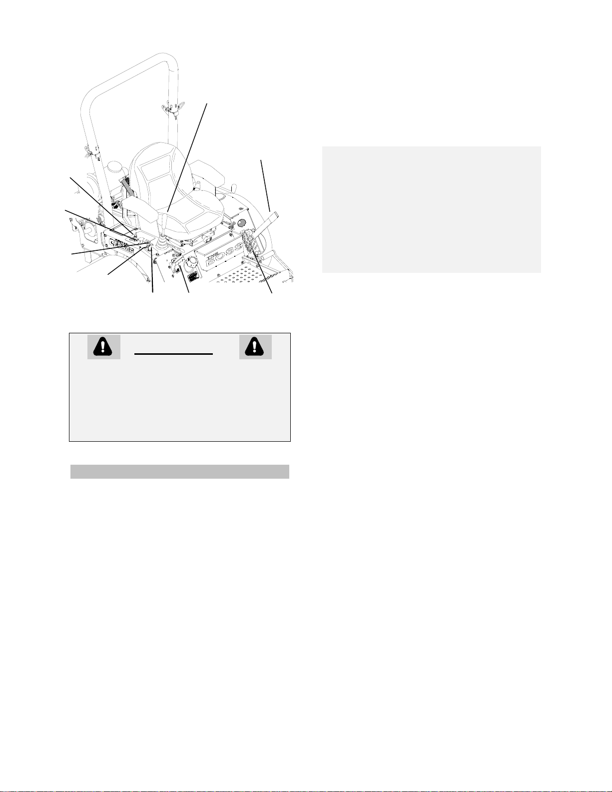
CONTROL LOCATIONS
WARNING
AVOID INHALING EXHAUST FUMES --
CARBON MONOXIDE GAS IS COLORLESS
AND ODORLESS, AND CAN CAUSE
UNCONSCIOUSNESS, AND IS POTENTIALLY
LETHAL. DO NOT RUN LAWN MOWER IN
GARAGE OR OTHER CONFINED AREA.
OPERATION - JOYSTICK
1. MOVE JOYSTICK CONTROL LEVER
TO neutral “DOWN” position.
2. SET PARKING BRAKE. Pull up to set.
3. DISENGAGE MOWER BLADE
CLUTCH by moving clutch switch to
“OFF” position.
4. PULL ENGINE CHOKE CONTROL to
full position for cold starts.
5. SET ENGINE THROTTLE TO 1/2
THROTTLE.
6. TURN IGNITION KEY to “START”
position and release to “RUN” as soon
as engine starts. NOTE: Prolonged
cranking will damage starter motor and
shorten the battery life.
7. ADJUST ENGINE THROTTLE AND
CHOKE for desired engine smoothness
and speed.
NOTE: When mowing, always run
engine at full throttle.
8. RELEASE PARKING BRAKE. Push brake
lever down to release.
IMPORTANT: Until the operator is familiar with
the Country Clipper Zero Turning
Radius Mower, he/she should follow
these recommendations: Disengage the
mower blades. Go very slowly until
thoroughly familiar with the machine.
Keep away from fences, buildings, and
other obstructions. Move the Joystick
Control Lever smoothly and slowly.
Practice until operation is smooth and
efficient.
9. TO DRIVE: Move the Joystick Control
Lever to the “UP” position. Move the
Joystick Control Lever forward to move
forward. Increasing forward movement
of the Joystick Control Lever will
increase the speed of travel. To reverse
the direction, pull the Joystick Control
Lever slightly back. To turn, move the
Joystick Control Lever toward the
direction you want to turn.. To turn on a
zero radius axis, go slowly and move
the Joystick Control Lever to the side
you wish to turn and slightly to the rear
at the same time.
10. Make sure mower blades are sharp and
secured tightly.
11. Clean the air intake screen on the
engine if necessary.
12. Perform any other maintenance as it
becomes necessary. (See the
“Maintenance” section of this manual.)
IMPORTANT: Before cutting grass, clutch must
be broken-in as follows: With engine at
full RPM engage deck until blades come
to full speed and then disengage until
blades come to a complete stop.
Repeat 10 times to seat clutch properly.
13. If Engine temp light comes on, turn
mower off and check coolant level. If
coolant level is full, take mower in for
service. Engine temp light is only on
Liquid cooled engines.
Joystick
Control Lever
Cut Height
Adjustment
Lever
Cut Height
Stop Pin
Blade Clutch
Switch
Ignition
Key
Choke
Throttle
Parking
Brake Lever
Engine Temp
Light
7
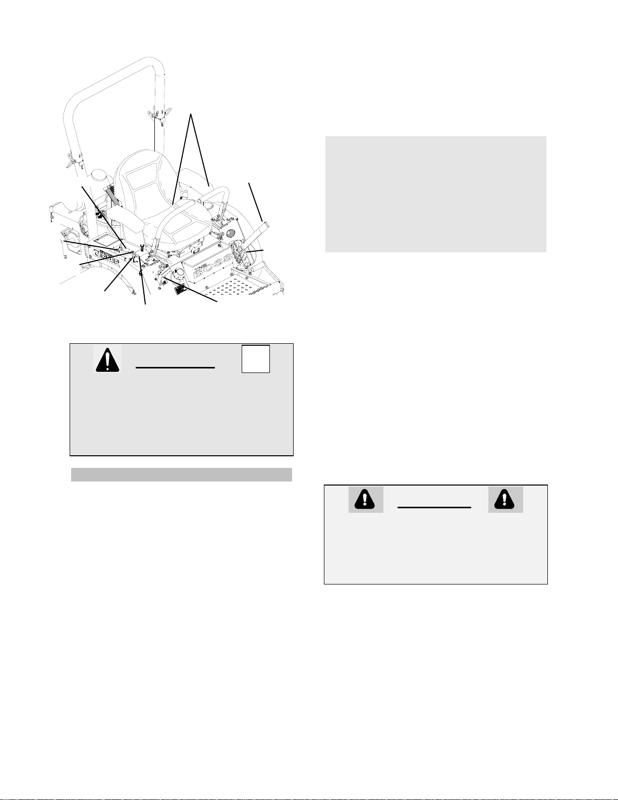
CONTROL LOCATIONS
WARNING
AVOID INHALING EXHAUST FUMES --
CARBON MONOXIDE GAS IS COLORLESS
AND ODORLESS, AND CAN CAUSE
UNCONSCIOUSNESS, AND IS POTENTIALLY
LETHAL. DO NOT RUN LAWN MOWER IN
GARAGE OR OTHER CONFINED AREA.
OPERATION – DUAL LEVER
1. MOVE STEERING CONTROL LEVERS
TO neutral “OUT” position.
2. SET PARKING BRAKE. Pull up to set.
3. DISENGAGE MOWER BLADE
CLUTCH by moving clutch switch to
“OFF” position.
4. PULL ENGINE CHOKE CONTROL to
full position for cold starts (on non-fuel
injected models).
5. SET ENGINE THROTTLE TO 1/2
THROTTLE.
6. TURN IGNITION KEY to “START”
position and release to “RUN” as soon
as engine starts. NOTE: Prolonged
cranking will damage starter motor and
shorten the battery life.
7. ADJUST ENGINE THROTTLE AND
CHOKE for desired engine smoothness
and speed.
NOTE: When mowing, always run engine
at full throttle.
8. RELEASE PARKING BRAKE. Push
brake lever down to release.
IMPORTANT: Until the operator is familiar with
the Zero Turning Radius Mower, he/she
should follow these recommendations:
Disengage the mower blades. Go very
slowly until thoroughly familiar with the
machine. Keep away from fences,
buildings, and other obstructions. Move
the Steering Control Levers smoothly
and slowly. Practice until operation is
smooth and efficient.
9. TO DRIVE: Move the Steering Control
Levers to the “IN” position. Move the
Steering Control Levers forward to move
forward. Increasing forward movement
of the Steering Control Levers will
increase the speed of travel. To reverse
the direction, pull the Steering Control
Levers slightly back. To turn, move one
Steering Control Lever slightly ahead of
the other. To turn on a zero radius axis,
go slowly and move one Steering
Control Lever forward and one Steering
Control Lever rearward. (For a right
hand turn the left hand Steering Control
Lever will be ahead of the right hand
Steering Control. For a left hand turn
the right hand Steering control will be
ahead of the left hand Steering Control.)
CAUTION
FOR SMOOTH, SAFE OPERATION, MOVE
THE CONTROL LEVER(S) IN A GENTLE,
SLOW MOTION. NEVER PULL OR PUSH THE
CONTROL LEVER(S) RAPIDLY, ESPECIALLY
ON GRADES.
10. BRAKING: To brake mower, gently
move the Control Lever(s) in the
direction opposite to travel. If the
parking brake is engaged with the
Joystick Control Lever in the “UP”
position or the Twin Sticks (if equipped)
in the “IN” position the engine will stop.
11. If Engine temp light comes on, turn
mower off and check coolant level. If
coolant level is full, take mower in for
service. Engine temp light is only on
Liquid cooled engines.
Ignition
Key
Choke
Throttle
Engine Temp
light
Blade Clutch
Switch
Steering Control
Levers
Cut Height
Adjustment
Lever
Cut Height
Stop pin
Parking
Brake Lever
8
12. CUTTING HEIGHT ADJUSTMENT:
With the Cut Height Adjustment Lever
latched into the top cut height latch,
insert Cut Height Stop Pin to desired
cutting height. Pull Cut Height
Adjustment Lever rearward and then to
the left to clear top cut height latch.
Lower Cut Height Adjustment Lever until
it rests on Cut Height Stop Pin.
13. ENGAGE MOWER BLADE CLUTCH:
Set the Blade Clutch Switch to the “ON”
position. The engine will not start if the
blade clutch is engaged. If the operator
is not in the seat, the engine will stop if
the clutch is engaged.
CAUTION
AVOID HILLS AND SLOPES. USE EXTREME
CAUTION WHEN MOWING UP OR DOWN
SLOPES. NEVER MOW ACROSS THE FACE
OF A SLOPE. IF A SLOPE MUST BE
ASCENDED, BACK UP THE SLOPE; DRIVE
FORWARD WHEN DESCENDING.
14. TO STOP:
A. Move Joystick Control Lever to
neutral position and then to the
“DOWN” position.
A2. Move the Twinstick handles to the
neutral position and then push both
handles out as far as they will go.
B. Disengage the mower blade clutch
by moving the clutch to the “OFF”
position.
C. Set the parking brake.
D. Slow engine speed with throttle to
slowest position.
E. Turn ignition key to “OFF” (left)
position.
F. Remove the key and wait for all
movement and all sound to cease
before dismounting.
CAUTION
WHEN LEAVING THE MOWER
UNATTENDED, ALWAYS REMOVE THE KEY
AND SET THE PARKING BRAKE, EVEN IF
JUST FOR A FEW MOMENTS. HELP
PROTECT CHILDREN AND OTHER
UNAUTHORIZED PERSONS FROM
ACCIDENTS.
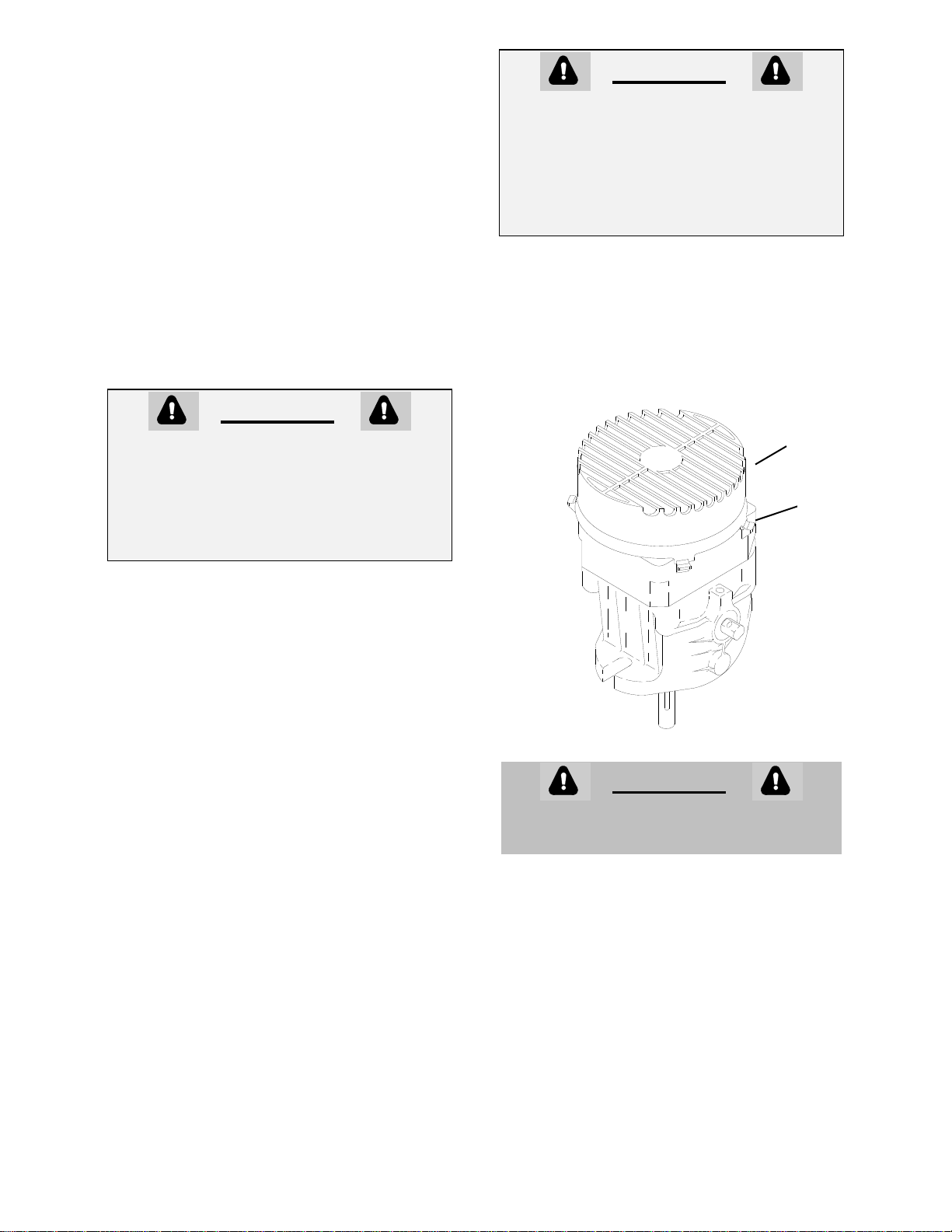
15. TO FREE WHEEL MACHINE:
Unscrew the bypass valve (½ turn
counter clockwise) found on the left front
of the right pump and the valve on the
right front of the left pump. Remove fan
shroud and use a 5/8” wrench to turn
bypass valve ½” turn.
CAUTION
NEVER OPERATE MOWER WITHOUT
DISCHARGE CHUTE
Fan
Shroud
Bypass
Valve

9
MOWING RECOMMENDATIONS
1. Keep mower blades sharp.
2. Make sure deck and discharge are
clean.
CAUTION
POWER MUST BE OFF TO CLEAN
DISCHARGE CHUTE. TURN ENGINE OFF
AND WAIT FOR ALL MOVING PARTS TO
STOP.
3. When mowing tall grass, make two
passes, mowing off 1/2 of the desired
cut on the first pass, and then the
desired height the second pass. Check
for hidden dangers first.
4. Go slowly for trimming.
5. Always cut grass with the engine at full
throttle speed. This “ENGINE” speed
allows the cutting blades to operate at
optimum cutting speed. Control
“GROUND” speed with the Control
Lever(s).
6. Vary ground speed to suit conditions
(i.e. go slower in tall thick grass, on hills,
wet conditions, etc.)

10
MAINTENANCE
CAUTION
BEFORE PERFORMING ANY MAINTENANCE, TURN OFF ENGINE
REMOVE KEY AND DISCONNECT SPARK PLUGS. USE EXTREME CARE WHEN WORKING ON
MACHINERY. DO NOT WEAR WATCHES OR JEWELRY. DO NOT WEAR LOOSE FITTING
CLOTHES, AND OBSERVE ALL COMMON SAFETY PRACTICES WITH TOOLS.
MAINTENANCE SCHEDULE
SERVICE WHEN
Check crankcase oil level --------------------------------------------------------------------- before each use
Clean grass from Hydrostat Oil Cooler------------------------------------------------------- before each use
Check air intake screen --------------------------------------------------------------------------- after each use
Clean grass under deck -------------------------------------------------------------------------- after each use
Check tire pressure ------------------------------------------------------------------------------- every 10 hours
Check battery fluid -------------------------------------------------------------------------------- every 10 hours
Sharpen mower blades -------------------------------------------------------------------------- every 10 hours
Clean air filter pre-cleaner element ----------------------------------------------------------- every 25 hours
Check Hydrostatic Transmission fluid -------------------------------------------------------- every 25 hours
Check drive belts ---------------------------------------------------------------------------------- every 50 hours
(20 hours break-in)
Service Air Cleaner Filter Element ---------------------------------------------------------- every100 hours
Change engine crankcase oil ------------------------------------------------------------------------- 100 hours
oil filter -------------------------------------------------------------------------- 200 hours
Change Hydrostat oil and oil filter ----------------------------------------------------------- every 500 hours
(100 hours break-in)
Replace air filter element --------------------------------------------------------------- annually or 500 hours
Check spark plugs ------------------------------------------------------------------------ annually or 500 hours
Service battery ---------------------------------------------------------------------------- annually or 500 hours
--------------------------------------------------------------------------------------------------------------------------------
Replace decals when illegible. Write factory for free replacement.

11
MAINTENANCE INSTRUCTIONS
1. ENGINE:
For complete maintenance and
operating information for your engine,
please refer to your engine operating
and maintenance instructions furnished
by the engine manufacturer and
included in your Country Clipper Zero
Turning Radius Mower information
packet.
NOTE: Air intake screen must be kept
clean. If plugged, engine may be
seriously damaged by over heating.
2. BATTERY:
CAUTION
BATTERY ELECTROLYTE IS A POISONOUS
AND CORROSIVE SULFURIC ACID
SOLUTION. AVOID SPILLING ON SKIN,
EYES, AND CLOTHING.
Keep the electrolyte level above the
plates in each cell by adding distilled
water as it becomes necessary. Add
water just before operating the mower to
mix the water with the solution. Be
careful not to overfill the battery -- the
electrolyte solution is corrosive and can
cause damage to surrounding metal
parts if it should spill. When taking the
battery out of the mower for servicing,
make sure to connect the cables to the
battery exactly as they were prior to
removal. Always disconnect the ground
( - ) wire first and always reconnect the
ground ( - ) wire last.
Keep the battery clean. Remove the
corrosion around the battery terminals
by applying a solution of one part baking
soda to four parts water. Coat all
exposed terminal surfaces with a light
layer of grease or petroleum jelly to
prevent corrosion.
NOTE: At temperatures below 32 degrees F (0
degrees C) the full charge state must be
maintained to prevent cell electrolyte
from freezing and causing permanent
battery damage.
3. TIRES:
Correct tire pressure is essential for
efficient operation of the mower. Check
tire pressure as requested in the
maintenance schedule. Inflate tires to
the pressures listed below:
Lug nuts should be checked regularly
for tightness.
4. MOWER BLADES:
Check sharpness of mower blades after
every 10 hours of operation. To
sharpen blades proceed as follows:
CAUTION
STOP ENGINE, REMOVE IGNITION KEY AND
SPARK PLUGS FOR SAFETY.
A. Remove bolt and blade washer
mounting blade on shaft. Remove
blade.
B. Blades should be discarded when
worn excessively.
C. Sharpen blades with a hand file,
electric grinder or blade sharpener.
Wear gloves and eye protection
when sharpening. Grind blade at
original 25 degree bevel.
Model Front tires Rear tires
All
Models 12 psi 12 psi
New Blade
25 degrees When notch
starts, discard
blade
DANGEROUS!
DO NOT USE
BLADE IN THIS
CONDITION
12
D. Check balance of blade by
positioning the blade on a nail or
blade balance pedestal. Grind the
blade on the end that is heavier until
both sides balance.
E. Install blade, blade washer, and
bolt. Make sure to tighten bolt to
100 ft-lbs.
5. V-BELTS:
All belts should be checked every 50
hours. Replace any belts found to be in
poor condition. All belts are equipped
with spring loaded belt tighteners and do
not require tightening adjustments.
6. LUBRICATION:
A. Engine: Follow engine
manufacturer’s recommendation.
B. Hydrostatic Transmission & Filter:
Follow instructions listed below.
DIRT OR WATER IN OIL CAN RUIN
THE HYDROSTATIC TRANSMISSIONS
Check the oil level in hydrostatic
transmission oil reservoir after every 25
hours of usage. Clean the oil reservoir
cap and the area around it prior to
removal. Check the oil level on the
dipstick. The proper oil level should
register between the marked hole on the
dipstick and the end of the dipstick.
Replenish as needed with 20W-50
Motor Oil. DO NOT OVER FILL. When
checking the oil level, be very careful to
keep the reservoir clean
Change the oil in the reservoir and
hydrostatic transmission filter after the
first 100 hours of use, then every 500
hours after that. Remove the filter and
be sure all oil has drained from the
reservoir. Replace with new filter (P/N
H-2026) and 20W-50 Motor Oil.
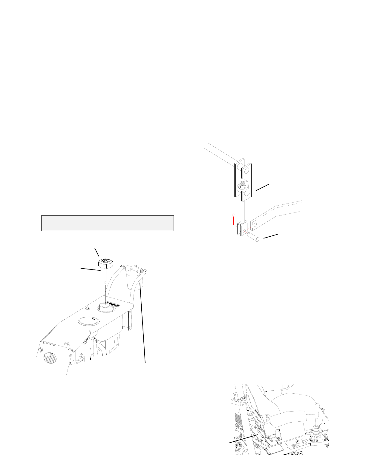
7. PARKING BRAKE ADJUSTMENT:
8. SEAT HOLD DOWN LATCH:
To release the seat hold down latch, lift
the latch bar while flipping the seat up
and forward.
A. Remove the clevis pin from the left brake.
B. Tighten the adjustment nut on the right
brake until it takes 28 pounds of pull to
lock the brake handle over center.
C. Install the clevis pin back on the left
brake.
D. Tighten the adjustment nut on the left
brake until it takes 56 pounds to lock the
brake handle over center, with both brakes
connected.
Clevis Pin
Adjustment Nut
Oil Reservoir Cap
Dipstick
Hydrostat Transmission
Oil Filter (located between
Hydro Pumps)
Latch
Bar

13
9. TWINSTICK CONTROL LEVER
FORWARD ADJUSTEMENT:
A. Remove the fender skirts from each
side of the machine.
B. Block up the unit so that the Drive
Wheels are off the ground.
C. Loosen the locknuts on the
turnbuckle on the upper linkage on
each side.
D. Push both control levers forward
until they hit the stops on the control
arms.
E. Bungee cord the arm at this position
and lengthen the upper linkage rods
until they bottom out the
transmissions.
F. Back off the turnbuckles ½ turn and
lock in place with the locknuts.
10. TWINSTICK CONTROL LEVER
NEUTRAL ADJUSTMENT:
A. Loosen the bolts holding the Neutral
Plate.
B. Pull back the control lever until the
wheel spin is zero.
C. Tilt the Control lever outward, using
the lever, position and tighten the
bolts holding the Neutral Plates.
11. TWINSTICK CONTROL LEVER
FORWARD TRACKING:
In a large open area, actuate the control
levers into the full forward position. If
the mower veers in either direction left
or right some adjustment is necessary.
If the mower veers to the right, then the
left transmission needs to be slowed
down. If the mower veers to the left,
then the right transmission needs to be
slowed down.
A. Stop the machine and shut off the
engine.
B. Slightly loosen the nuts around the
turnbuckle on the faster side.
Lengthen the linkage rod by ¼ turn
increments, retighten and retest,
until the mower tracks straight.
C. Once the tracking is to the
operator’s liking, completely tighten
the nuts on the turnbuckle.
Recheck and adjust the Neutral
Plate, if required.
D. Reinstall the side plates and tighten
all bolts.
E. If the forward tracking still requires
“fine tuning”, use the on-the-fly fine
adjustment knob on top of the
fender cap, next to the Control lever.
Make small adjustments to full
forward as needed.
12. TO ADJUST “IN” OR OPERATING
POSITION OF THE TWINSTICK
STEERING CONTROL LEVERS:
If the Control levers are too close in the
center or the Control levers drag on the
Neutral Plate, adjust as follows.
A. Tilt the Control lever outward,
loosen the locknut and adjust the
Neutral
Plate
Handle
Mount Bolts
Control Arms
Forward
Note Mark, LH
Thread End
Shorten length
to bottom out
transmission,
then back off ½
turn.

14
bolt until the gap between the
handles is correct or the Control
lever does not rub the Neutral
Plates.
B. Tighten the locknut after the
adjustment is made.
NOTE: To prevent damage to Control Linkages
the Control Lever must always hit on the
Stop Screws. Never adjust Stops out so
that the Control Lever “bottoms” out on
other parts of the linkage.
13. ALIGNING THE HANDLES:
Once forward tracking and neutral are
set, the handle position may be adjusted
for operator comfort and alignment.
Loosening the handle mount bolts,
move the levers into the desired position
and re-tighten the mounting bolts
securely.
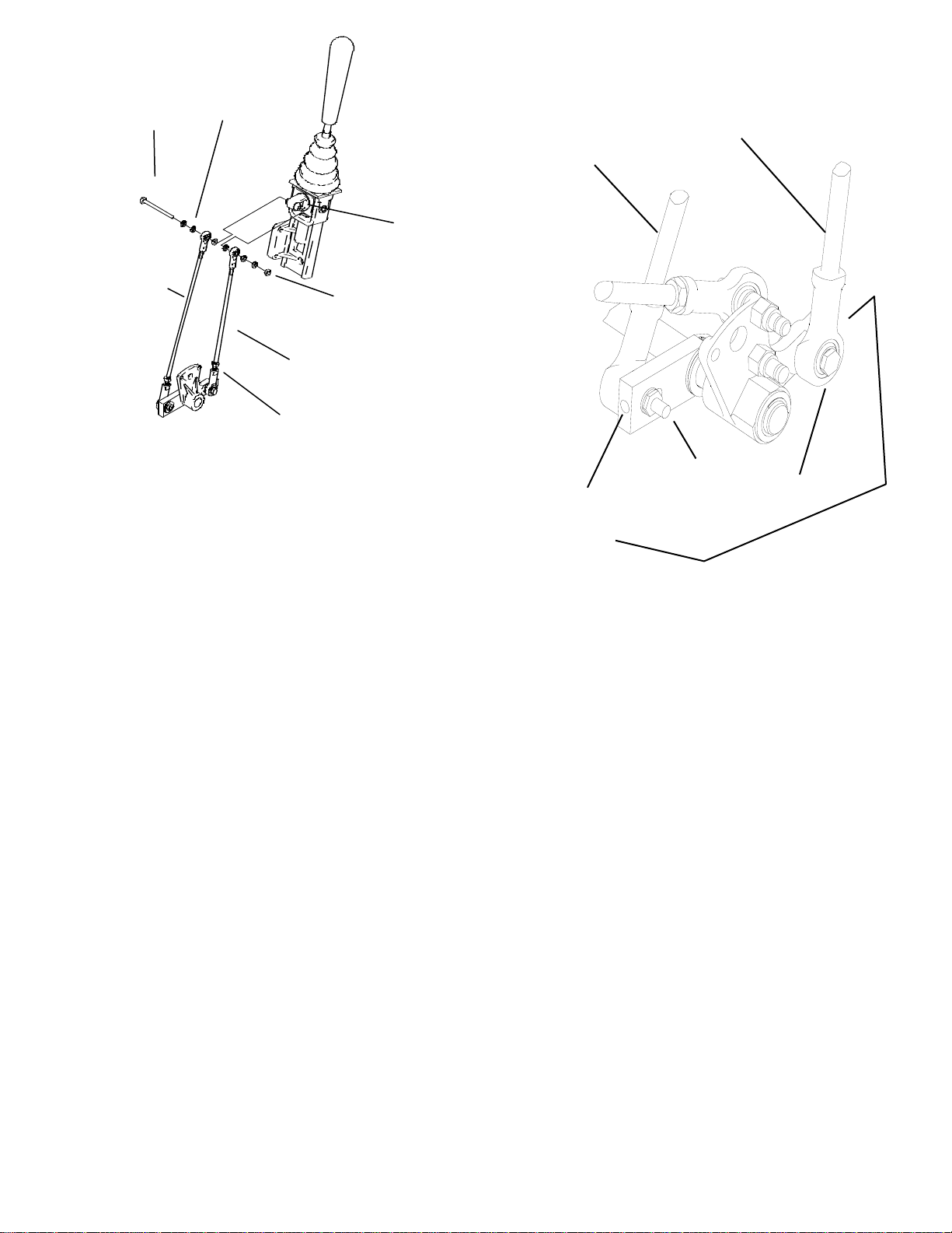
14. JOYSTICK CONTROL LEVER
NEUTRAL ADJUSTMENT:
With the engine running, if the machine
travels in either direction when the
Joystick Control Lever is in the neutral
“DOWN” position, stop the engine,
elevate the rear wheels clear of the
ground and adjust as follows:
A. Remove the right hand fender skirt
exposing the Joystick Control Lever
Assembly.
B. Start the engine.
C. Run engine at fast idle with Joystick
Control Lever in the “DOWN”
position.
D. Loosen the locknuts tightened
against the rod end ball joints on the
Upper Linkage Assembly that
corresponds to the wheel that is
turning. Note: One of these is a left
hand nut and will have to be turned
backwards.
E. Adjust the Neutral Position by
turning the rod in the upper linkage
until the wheel stops turning.
F. Retighten the locknuts on the upper
linkage assembly and check to
make sure the drive wheel is still not
turning.
G. Repeat steps B through F for other
side, if needed.
H. Shut off engine before removing
from blocks. Replace fender skirt.
15. JOYSTICK ADJUSTMENT CONTROL
LEVER DETENT:
If the Joystick Control Lever does not
lock in the “UP” position, turn the detent
adjustment screw clockwise until a
desirable locking action is obtained. If
the Joystick control Lever is hard to
slide up and down, turn the detent
adjustment screw counter-clockwise
until a desirable sliding action is
obtained.
16. JOYSTICK CONTROL LEVER
SENSITIVITY ADJUSTMENT:
To change the sideways turning
response, adjust as follows:
A. Remove the right hand fender skirt
exposing the Joystick Control Lever
assembly.
B. Remove the cross bolt, nut, and
spacers
C. Reassemble the spacers as desired.
(2) spacers between the rod end
ball joints and the joystick pivot shaft
will quicken the side to side
response, (1) spacer slows the
response.
NOTE: It is important that there is at least one
spacer on each side of the rod end ball
joints to prevent damage. Also the
small diameter of the spacer must point
towards the rod end ball joint.
Lock Nut
Adjustment
Bolt
15
17. ADJUSTING FOR STRAIGHT
FORWARD TRACKING:
In a large open area, actuate the
Joystick Control lever into the full
forward position. If the mower veers in
either direction left or right some
adjustment is necessary.
A. If the mower veers to the right, then
the right hydrostat needs to be sped
up. If the mower veers to the left,
then the left hydrostat needs to be
sped up.
B. Stop the machine and shut of the
engine.
C. Slightly loosen the bolt at the lower
end of the upper linkage assembly
on the side that is slower. Using a
1/8” allen wrench turn the setscrew
¼ turn in. It may take several test
drives to get the mower to track
straight forward.
D. Once the tracking is to the operators
liking, completely tighten the bolt on
the control linkage assembly that
was loosened earlier.
E. Recheck to make sure neutral
adjustment has not been effected.
See picture below:
18. JOYSTICK CONTROL LEVER
SHIFTING FORCE ADJUSTMENT:
To change the amount of force required
to shift the joystick control lever adjust
as follows:
A. Heavier Force to Move Joystick
Control Lever: Loosen nuts on rear
Damper mounting studs. (Both
sides) Move rear of dampers down
in slots. Re-tighten nut.
B. Lighter Force to Shift Joystick
Control Lever: Loosen nuts on rear
Damper mounting studs. (Both
sides) Move rear of dampers up in
slot. Re-tighten nut.
Cross Bolt
Joystick
Pivot Shaft
Spacers (3)
per side
L.H. Linkage
Assembl
y
R.H. Linkage
Assembly
Loosen this nut
(Left hand threads)
Loosen this nut
(Right hand threads)
Setscrews
to adjust
forward
tracking
R. H. Upper
Linkage
Assembly
L.H. Upper
Linkage
Assembly
Loosen bolt on
linkage that needs
adjusting

16
See picture below:
Shift Arm
Adjustment bolt in
slot in engine guard
Right Engine
Guard
Damper

17
DRIVE BELT CONFIGURATION
VIEWED FROM FLOOR LOOKING UP
Right Hand
Pump Pulley Left Hand
Pump Pulley
Motor Pulley
Belt D-3777 Idler Arm
Q
RS LATCH CONFIGURATION
Latch Plate
Hook Keeper
Deck Hook

18
ENGINE TO DECK BELT ROUTING
DECK BELT ROUTING
DECK BELT
60” D-3796 B-124
72” D-3797 B-142
ENGINE TO DECK BELT
60” D-3809 B-120
72” D-3796 B-124
Spring

19
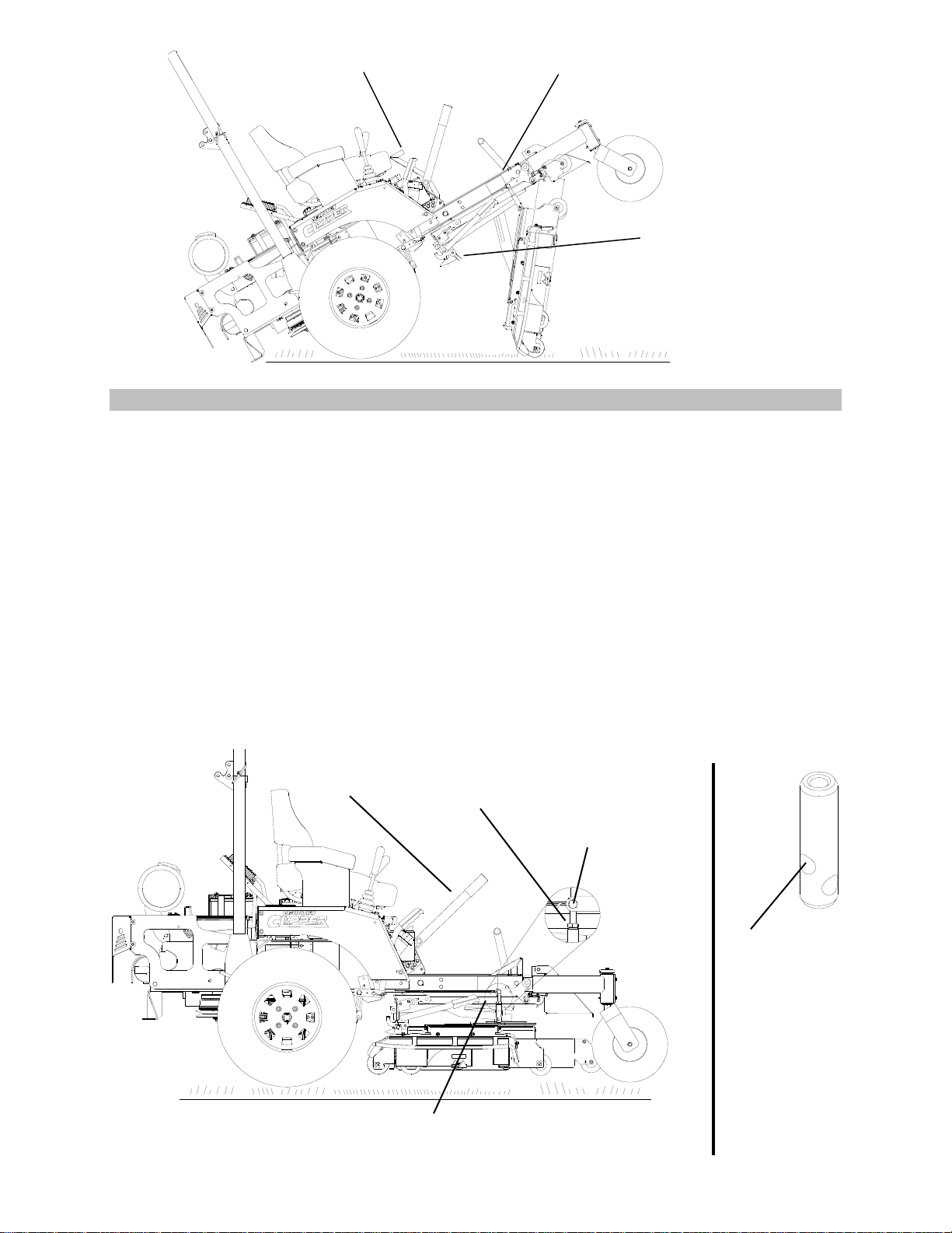
RAISING AND LOWERING THE DECK
FOR SERVICING
1. RAISING THE DECK:
A. Remove cut height adjustment pin
and completely lower the cut
height adjustment lever. Re-insert
the cut height adjustment pin into
the 3-1/2” cut height position (this
will lock the cut height adjustment
lever into the lowest position).
B. Release engine to deck belt
tightener located behind the left rear
tire.(see illustration page 19) Flip up
the foot deck to allow access to
the engine to deck belt. Roll the
belt off the center spindle. Hook the
belt onto the bolt protruding out of
the top of the foot deck support
angle.
C. On the right side of the mower, lift
and hold up on the hook keeper.
Lift up on the release handle to
disconnect the back of the deck.
The latch plate should catch and
hold the release handle rod in place.
(To adjust the latch plate, see Page
20.)
D. Position the front caster wheels so
they are away from the deck (such
as the tractor would be traveling in
reverse).
E. Lift the nose of the deck until the deck is
standing vertical (lifting can be made
easier if someone stands on the rear
bumper of the tractor). IMPORTANT
NOTE: MAKE SURE THAT THE DECK
IS LIFTED FAR ENOUGH TO GO
COMPLETELY “OVER-CENTER”.
This will prevent the deck from falling
down when servicing the underside of
the mower deck.
2. LOWERING THE DECK:
A. Push the bottom (back) of the deck
towards the rear of the tractor. Lower
the deck until it rests on the ground.
B. Lift up on the latch plate to release the
release handle rod. Push down on the
release handle until deck hooks lock into
place.
C. Re-install the Engine to Deck Drive belt
onto ALL of the pulleys, including the
clutch. Insure that the Engine to Deck
Drive Belt is properly routed onto all
of the pulleys and idlers in the drive
train.
D. Carefully rotate the Deck Belt Tension
Latch to re-tension the Engine to Deck
Drive Belt.
Front Caster Wheels
positioned out of the way
QRS Latch
Cut Height
Adjustment Pin
Lift Here
Foot Deck
Cut Height
Adjustment Lever
20
LEVELING THE DECK
1. Move the tractor to a hard, level surface (i.e. concrete or blacktop).
2. Set the tire pressure on all four tires to 12 psi.
3. Rotate the blade you are going to measure to run parallel with tractor frame, front to back.
4. Set the Deck Cut Height Lever to the 4’ cutting position.
5. Loosen the Deck Hanger Bolt Jam Nuts.
6. Adjust the Front Left Hand Deck Hanger Bolt until the front edge of the Left Hand Blade is
Approximately 4” from ground.
7. Adjust the Front Right Hand Deck Hanger Bolt until the front edge of the Right Hand Blade is
within 1/8” of the Front Left hand Blade measurement. NOTE: “On 72” Decks” If the Front Right
Hand blade measurement can not be obtained it will be necessary to shorten or lengthen the
Adjustable Drag Bar Link on the right hand side of the deck suspension. Lengthening the
Adjustable Draglink lowers the front end of the Right Hand blade and shortening the Adjustable
Drag Bar Link raises the front of the Right Hand blade.
8. Adjust both Rear Deck Hanger Bolts until the back of the blades are 1/8” to 1/4” higher from
the ground than the front of the blades. Inspect that the deck is solidly hanging on all four Deck
hanger Bolts. Adjust rear Deck Hanger Bolts accordingly.
9. Inspect all of the above measurements. Tighten all four Deck Hanger Bolts Jam Nuts.
Jam Nut Right Front Deck
Hanger Bolt
Lift Handle
Adjustable Drag Bar
Note: If you run out of
threads during the
adjustment process,
remount the deck
mounting in this upper
hole.
IF ATTEMPTING TO
ADJUST DECK HIGHER
THAN DESIGN
SPECIFICATIONS, DECK
DRIVE FAILURE CAN
OCCUR.
Engine to Deck Drive Belt
hooked to bolt.
QRS Latch in locked
up position.
Foot Deck in up position
Table of contents
Popular Lawn Mower manuals by other brands


Craftsman
Craftsman 917.376392 owner's manual

Husqvarna
Husqvarna 917.379131 Owner's owner's manual

Victa
Victa 460 Utility Operator's manual

Texas
Texas Smart G-Force SB900 user manual

Country Clipper
Country Clipper Jazee Safety instructions & operator's manual

Poulan Pro
Poulan Pro PB195H42LT Repair parts manual


