13
DeutschEnglish Français Italiano Español Português Nederlands
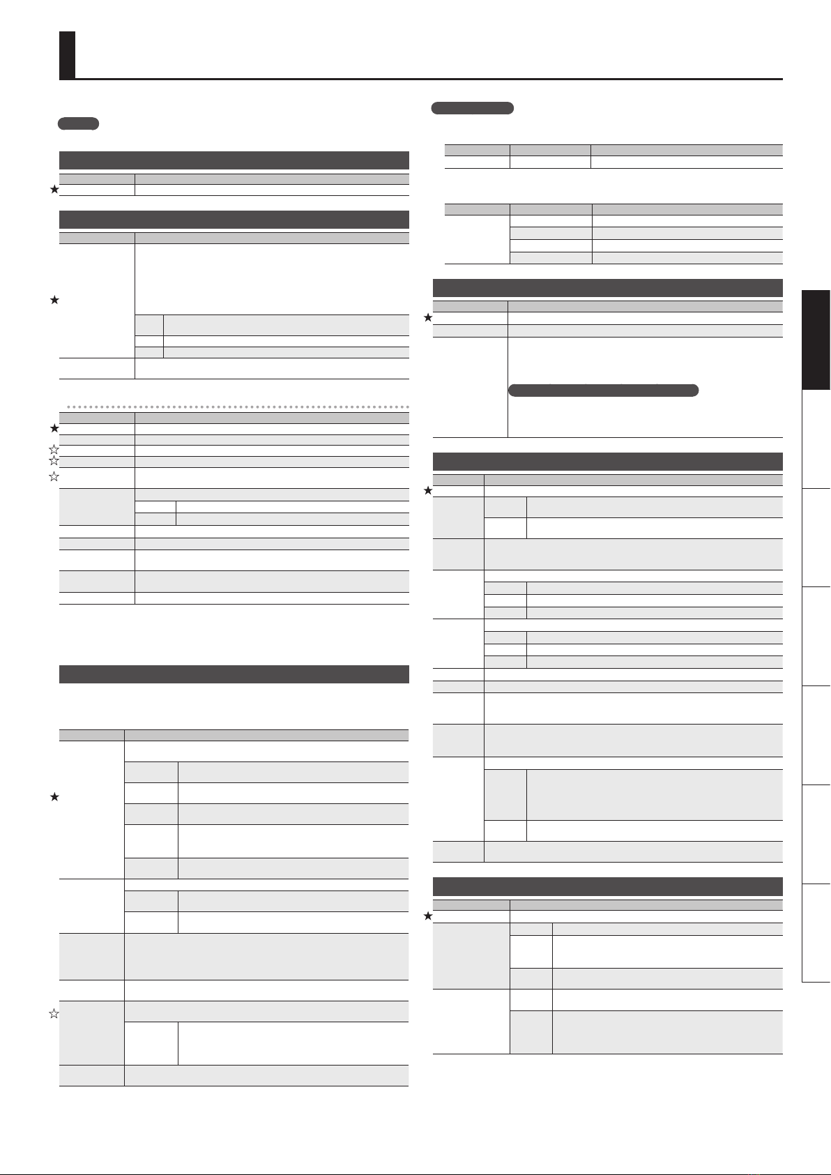
System Settings
Press the [SYSTEM] button to edit.
MEMO
For details on +/,marks, refer to“Basic Procedure for Editing the Settings”(p. 5).
Specifying the Output System (Sys: Output)
Parameter Explanation
Output Refer to “Specifying the Output System (Sys: Output)” (p. 3).
Settings of the GK Pickups (GK: )
Parameter Explanation
Connect
The GP-10 comes equipped with a function that automatically determines
whether or not a GK connection exists and switches the internal settings
accordingly. This makes it possible for you to all functions other than a
Modeling/Alternate Tuning (eects, tuner, etc.) when you’ve connected only
to the GUITAR INPUT. You should ordinarily use AUTO (default). In cases where
the auto-detect function does not operate correctly, (for example, when you
are using a Divided pickup other than the GK-3), change the setting.
AUTO The presence of a GK connection is detected automatically and the
internal settings are switched accordingly.
OFF Settings appropriate for a GUITAR INPUT connection are always used.
ON Settings appropriate for a GK connection are always used.
Setting Refer to “MEMO: GK settings”(p. 3) and “GK Set Selection for the Patch (Patch:
GK Set)” (p. 11).
Settings of the GK set 1–3 (GK 1–3: )
Parameter Explanation
Type Refer to“Setting Up the GK Pickups”(p. 3).
Scale *1 Refer to “Specifying your guitar’s scale length” (p. 3).
Distance 1–6 *3 Refer to “Specifying the distance from the bridge”(p. 3).
Sens 1–6 Refer to“Adjusting the pickup sensitivity” (p. 3).
PU Phase *1 This sets the phase for the divided pickup and normal pickup. Set this to
“NORMAL,” and if the low-frequency range is cut, set this to “INVERSE.”
PU Direction *1
This sets the direction for the divided pickup’s installation.
NORMAL Positioned such that the cable exits near the 6th string.
REVERSE Positioned such that the cable exits near the 1st string.
Piezo Tone L *2 Adjusts the low-frequency range.
Piezo Tone H *2 Adjusts the high-frequency range.
Sw Position *1 This exchanges the function for the GK-3’s, GK-2A’s or GC-1’s [S1], [S2] buttons
(REVERSE).
Dwn Tune Shift If the guitar you’re using has been tuned down, specify the number of
chromatic steps by which it has been down-tuned.
Nrml PU Gain Adjusts the input level of the normal pickup.
*1 This is not shown if “GC-1”is selected as the pickup type.
*2 This setting applies if the PU TYPE is set to“PIEZO–.”
*3 This parameter is not shown if you select“GC-1”or one of the piezo-type pickups as the pickup
type.
System Settings for the Pedals and Switches (SysCtl: )
Species the functions that are assigned to the [CTL 1], [CTL 2] pedals and the expression pedal.
With the factory settings, “PATCH SETTING”is selected; each pedal is assigned the most suitable
function for that patch. If you want the pedals to operate in the same way regardless of which patch
is selected, choose something other than “PATCH SETTING.”
Parameter Explanation
CTL 1–4 Func
GKSW 1–2 Func
EXPSW Func
Settings for the GP-10’s [CTL 1], [CTL 2] pedals, external footswitches (CTL 3, CTL
4), the GK pickup’s [S1], [S2] buttons, and the expression pedal switch.
PATCH
SETTING
Choose this if you want the function of the pedals and switches
to change for each patch.
PATCH UP Moves from the current patch number to a number that is larger
by the value of the Patch Up setting.
PATCH DOWN Moves from the current patch number to a number that is
smaller by the value of the Patch Down setting.
PATCH SEL
Moves to the patch that is specied by the Patch Select.
* For details on other values, refer to“Pedal and Switch Settings
for Each Patch (Ctl: )”(p. 11).
TUNER ON/
OFF Turn the tuner on/o.
Mode
This sets the behavior of the value each time the switch is operated.
MOMENTARY The normal state is O (minimum value), with the switch On
(maximum value) only while the footswitch is depressed.
TOGGLE The setting is toggled On (maximum value) or O (minimum
value) with each press of the footswitch.
C1–4 Pat. Up
C1–4 Pat. Dwn
GKSW1–2PUp
GKSW1–2PDwn
Species the distance of the increment/decrement from the current patch
number when PATCH UP/DOWN is selected and you press the pedal or switch.
C1–4 Pat. Sel Species the patch number to which you will move directly when PATCH SEL is
selected and you press the pedal or switch.
EXP 1 o Fn
EXP 1 on Fnc
EXP 2 Func
GKVOL Func
Settings for the GK pickup’s GK volume, the GP-10’s expression pedal (when the
pedal switch is OFF and when it is ON), and external expression pedals.
PATCH
SETTING
Choose this if you want the function of the pedals to change for
each patch.
* For details on other values, refer to“Pedal and Switch Settings
for Each Patch (Ctl: )”(p. 11).
Asgn Hld Sw Species whether the state of the expression pedal and GK volume will be (ON)
or will not be (OFF) reected by the next patch when you switch patches.
Example setting
In all patches, switch delay on/o by pressing the [CTL] pedal
Make the following parameter settings.
Buttons Parameter Value
[SYSTEM] SysCtl: CTL 1 Func DELAY ON/OFF
In all patches, use the [CTL 1], [CTL 2] pedals to increase/decrease the patch
number by ten
Buttons Parameter Value
[SYSTEM]
SysCtl: CTL 1 Func PATCH DOWN
SysCtl: CTL 2 Func PATCH UP
SysCtl: C1 Pat. Down 10
SysCtl: C2 Pat. Up 10
USB Audio Settings (USBAudio: )
Parameter Explanation
In Lv Adjusts the volume of the digital audio signal from USB (computer).
Out Lv Adjusts the volume of the digital audio signal output to USB (computer).
Routing
Species the routing for USB audio. You can record the sound of the GP-10
into your DAW, play back the recorded sound from your DAW and monitor
it on the GP-10, or re-guitar/re-amp your recording. For details, refer to the
“Parameter Guide” (PDF).
What does it mean to Re-Guitar/Re-Amp?
This is the technique in which an original signal unprocessed by modeling or
eects is recorded on the DAW, allowing you to modify the modeling sound
or amp sound later to create the nal result. This gives you the freedom to
change the sound after you’ve nished recording.
Guitar Performance MIDI Output Settings (MIDI: )
Parameter Explanation
On/O If this is “OFF,” guitar performance data will not be transmitted from MIDI OUT.
Mode
MONO In this mode, one channel per string is used, thus using a total of six
channels.
POLY In this mode, the messages for all six strings are transmitted over a
single channel.
Chromatic
When using string bending or other such techniques to gradually change the pitch
with the guitar or bass, you can set the GP-10 so that the pitch of the MIDI messages
being output changes in semitone increments.
Hold Pedal
Species the pedal to which the Hold function is assigned.
OFF The Hold pedal is not assigned.
CTL 1 The [CTL 1] pedal is the Hold pedal.
CTL 2 The [CTL 2] pedal is the Hold pedal.
Pedal Bend
Species whether expression pedal operations transmit pitch bend messages.
OFF Pitch bend is not transmitted.
DOWN Bend-down data is transmitted.
UP Bend-up data is transmitted.
Bend Range Species the maximum range of change for pitch bend messages.
Data Thin If this is “ON,” pitch bend data will be thinned-out to reduce the volume of MIDI data.
String Ch
Species the MIDI channel used to transmit guitar performance data. If Mode is set
to “MONO,” the data will be transmitted using six channels starting with the channel
you specify here.
Dynamics
Adjusts the sensitivity of the tone’s volume (velocity) change.
The further you raise this setting, the more easy it becomes to produce higher values
for velocity.
Play Feel
Adjusts the velocity change curve of the tone.
FEEL1–4
FEEL1 is the mode that gives sounds the broadest variation in volume
based on the picking dynamics. As the setting number is increased,
it becomes easier to produce high volume sounds even with weaker
picking. This allows you to play with consistent volume, whether you tap
the strings or use rough picking.
NO DYNA In this mode, sounds are played at a xed volume regardless of the
picking strength.
Low Velo Cut Adjust this if simply touching a string causes a note to be unintentionally triggered.
Raising this value will make it more dicult to trigger notes.
Tuner Settings (Tuner: )
Parameter Explanation
Pitch Species the reference pitch.
Sound
MUTE Sound will not be output while tuning.
BYPASS
While tuning, the sound from the GK IN connector/GUITAR IN
jack will be output without change.
All modelings and eects will be o.
EFFECT Allows you to tune while hearing the current eect/modeling
sound.
Function
ENABLE From the Play screen, pressing the [I] and [H] pedals
simultaneously will enter Tuner mode.
DISABLE
From the Play screen, pressing the [I] and [H] pedals
simultaneously will not enter Tuner mode.
* From the Play screen, pressing the [J] button will enter Tuner
mode.