BOSSCO SMARTHITCH2 RT3 POWER-V User manual

DRIVEN TO BE THE BEST
MSC04082-9
RT3 POWER-V BLADE
WITH SMARTHITCH2
TM
INSTALLATION MANUAL
TABLE OF CONTENTS
WARNINGS................................................................................................................................... 2
SNOWPLOW MOUNTING & REMOVAL PROCEDURE.............................................................. 3
SNOWPLOW ASSEMBLY PROCEDURE .................................................................................... 4
ELECTRICAL SYSTEM WIRING PROCEDURE.......................................................................... 9
HEADLIGHT ADAPTER INSTALLATION PROCEDURE............................................................. 14
ELECTRICAL SYSTEM WIRING SCHEMATIC PLOW SIDE) .................................................... 15
ELECTRICAL SYSTEM WIRING SCHEMATIC TRUCK SIDE) .................................................. 16
ELECTRICAL SYSTEM WIRING DIAGRAM ................................................................................ 17
RT3 V-BLADE MANIFOLD WIRING DIAGRAM ........................................................................... 18
HYDRAULIC VALVE ASSEMBLY PARTS LIST........................................................................... 19
HEADLIGHT AIMING PROCEDURE............................................................................................ 20
HYDRAULIC POWER UNIT FILL PROCEDURE ......................................................................... 21
V-BLADE CONTROLLERS ........................................................................................................... 22
TROUBLESHOOTING GUIDE...................................................................................................... 26
RECOMMENDED PUSHBEAM HEIGHT ..................................................................................... 32
RECOMMENDED BOLT TORQUE .............................................................................................. 32
BOSS PRODUCTS / Northern Star Industries, Inc. reserves the right under its continuous product improvement policy to change construction or
design details and furnish equipment when so altered without reference to illustrations or specifications used herein.
This product is covered under one or more of the following patents:
5,568,694 4,074,448 4,658,519 6,108,946 6,170,178 6,134,814
Other Patents Pending
BOSS PRODUCTS
A Division of Northern Star Industries, Inc.
P.O. Box 787 Iron Mountain MI 49801-0787
www.bossplow.com

WARNING
Many newer trucks are equipped with air bags. DO NOT under any circumstances disable or remove or
relocate any sensors or other components related to the operation of the air bags.
WARNING
Always follow the vehicle manufacturer’s recommendations relating to snowplow installation. For
recommended vehicle models refer to the BOSS Snowplow Application Chart and Selection Guide.
WARNING
Vehicles equipped with air bags are designed such that the air bags will be activated in a frontal collision
equivalent to hitting a solid barrier such as a wall) at approximately 14 mph or more, or, roughly speaking,
a frontal perpendicular collision with a parked car or truck of similar size at approximately 28 mph or more.
Careless or high speed driving while plowing snow, which results in vehicle decelerations equivalent to or
greater than the air bag deployment threshold described above, would deploy the air bag.
WARNING
Read this manual carefully before operating this snowplow.
WARNING
When transporting, position plow so as not to block vision or plow headlights.
WARNING
DO NOT change blade position when traveling.
WARNING
DO NOT exceed 40 mph when transporting plow.
WARNING
DO NOT exceed 14 mph when plowing.
WARNING
Always lower blade when vehicle is not in use.
WARNING
Make sure plow is properly attached before moving vehicle.
WARNING
To comply with Federal Regulations and to assure a safe vehicle, the Front Gross Axle Weight Rating
FGAWR), Rear Gross Axle Weight Rating RGAWR), and the Gross Vehicle Weight Rating GAWR) must
not be exceeded at any time.
WARNING
Due to the variety of equipment that can be installed on this vehicle, it is necessary to verify that the Front
Gross Axle Weight Rating FGAWR), Rear Gross Axle Weight Rating RGAWR), and the Gross Vehicle
Weight Rating GAWR) are not exceeded at any time. This may require weighing the vehicle and adding
ballast as necessary. It may also limit payload capacity of the vehicle. It is the operator’s responsibility to
verify that these ratings are not exceeded.

Snowplow Mounting Procedure
3
Figure 1. Mounting and Removal Instructions MSC04606
Snowplow Assem ly Procedure
4
Sn wpl w Assembly
Pr cedure
N te: This manual is used for the installation of all V-
Plows. Part numbers and illustrations may vary.
1. Begin the assembly procedure by cutting down
each corner of the plow box so that each wall of
the box will lie flat on the floor. Lay the top of the
box flat on the floor. The top of the box can be
used as a mat and will help prevent scratching the
blade halves during installation.
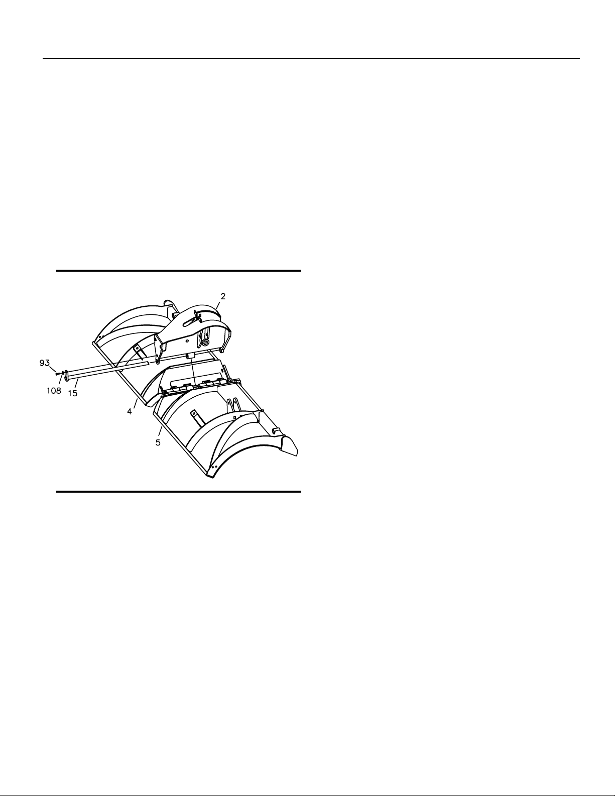
2. Remove Left Blade Half 5) and Right Blade Half
4) from the crate. Lay each blade half flat on the
box top, face down.
Figure 2. Blade Assembly Procedure. G10123
3. Align the center bushings on Left Blade Half 5)
with the center bushings on Right Blade Half 4).
Position CHA09716 Center Section 2) on top of
both blades so that all bushings align.
4. Insert MSC01507 Center Hinge Pin 15) through
Left Blade Half 5), Right Blade Half 4) and
Center Section 2).
5. Secure Center Hinge Pin 15) to the top of Center
Section 2) using one HDW01771 3/8”-16 X 1 ¼”
Hex Head Cap Screw 93), and one HDW01718
3/8” Split Lock Washer 108).
N te: Plow shoes are optional. If added they should
be mounted flush with the bottom of the cutting edge
when the plow is mounted on the truck to be used for
plowing. When plowing on a solid level area parking
lots, roads, and driveways) plow shoes can be raised
up to increase cutting edge contact on the plowed
surface. When plowing dirt, gravel, or grass plow
shoes should be lowered below the cutting edge
surface to prevent the plow from digging into the
plowed surface.

Snowplow Assem ly Procedure
5
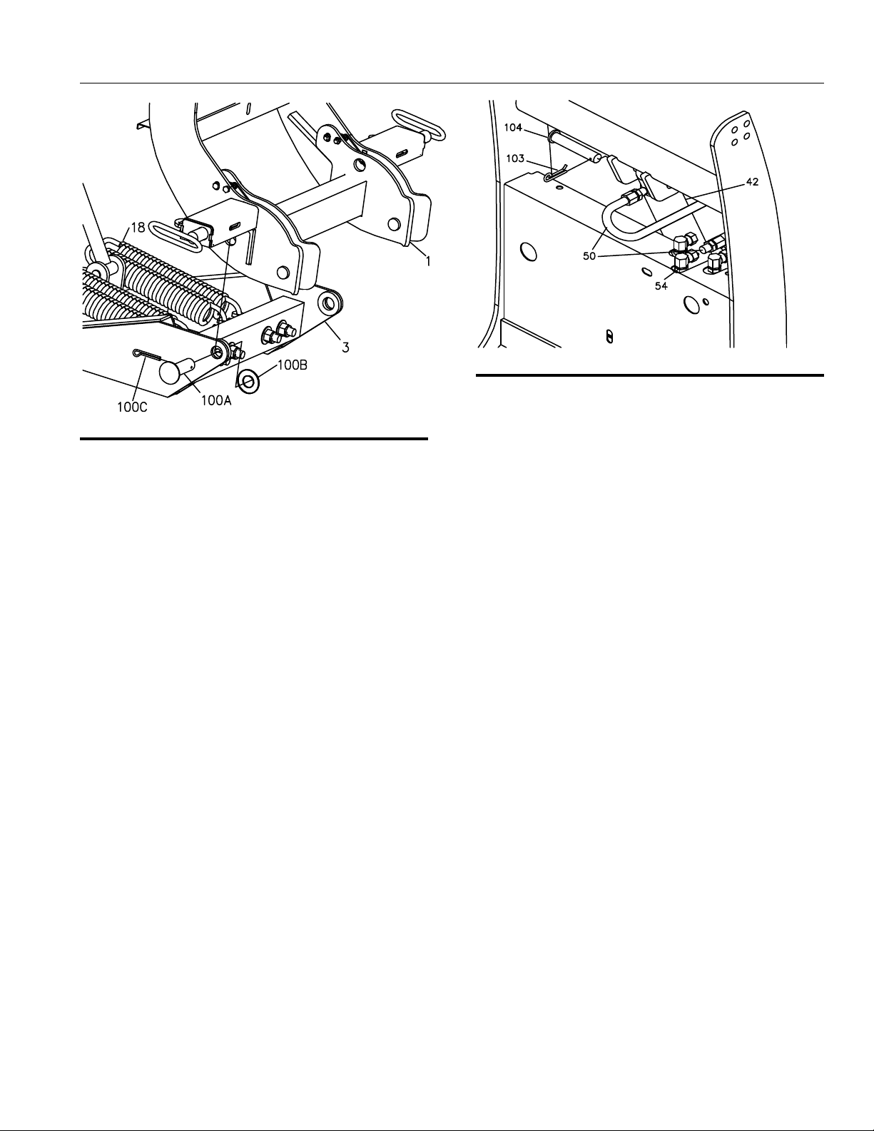
Figure 3. Push Frame Assembly Procedure. G10122
6. Stand Blade Assembly and Center Section 2) on
the Cutting Edges with both wings forward in the
scoop position.
7. Remove the loose Horizontal Hinge Pin 102C)
that is inserted in the Center Section 2).
8. Slide TFR09708 Push Frame 3) into Center
Section 2). Re-insert Horizontal Hinge Pin 102C)
through Center Section 2) and Push Frame 3)
then secure with washer 102B) and nut 102A).
9. Attach Lift Cylinder 42) to Push Frame 3) with
HDW05563 Clevis Pin 104) and HDW05544
Hairpin Cotter 103).
10. Hook MSC04200 Spring Yoke 11) to the cross
rod inside Center Section 2).
11. Hook one end of MSC01509 Trip Spring 18) to
Spring Yoke 11). Attach the opposite end of Trip
Spring 18) to the rear angle of Push Frame 3)
using HDW05601 Eyebolts 98), 5/8” Flat
Washers 112) and 5/8” Self-Locking Nuts 111) .
Tighten Self-Locking Nuts 111) finger tight.
12. Attach HYD09731 Angle Cylinders 40) to Center
Section 2) using HDW01706 5/8”-11 X 4” Hex
Head Cap Screws 90) and HDW01709 5/8”-11
Self Locking Nuts 111). DO NOT over-tighten the
nuts.
N te: You should be able to slightly slide the cylinder
up and down on the bolt after it has been tightened.
Figure 4. Angle Cylinder Installation. G10121
13. Pull both wings back into the ‘V’ position.
14. Hook one end of Return Spring 19) to the top
hole on Center Section 2). Hook the opposite end
of Return spring 19) to the blade spring mounting
bracket using ½” Spadebolt 97A), ½” Flat Washer
97C), and ½” Self-Locking Nut 97B). Tighten
Spring 19) until there is a 1/32” space between
spring coils. Repeat this process for Return Spring
19) on the opposite side of the plow.
15. Install one Push Nut Retainer 97D) on each end
of the Return Spring 19).
N te: Be sure Push Nut Retainer’s flanges are
pointing away from the Eyebolt and toward the open
end of the Return Spring.
16. Bolt the rod end of Angle Cylinder 40) to each
blade half using 5/8”-11 X 4” Hex Head Bolt 90)
and 5/8”-11 Self Locking Nuts 111). DO NOT
over tighten bolts. Repeat this process for Angle
Cylinder 40) on the opposite side of the plow.
N te: You should be able to slightly slide the cylinder
up and down on the bolt after it has been tightened.
Snowplow Assem ly Procedure
6
Figure 5. Coupler Assembly to Push Frame. G10119
17. Align pivot holes of Coupler Assembly 1) and
pivot holes of Push Frame 3).
18. Insert 1” X 2 ½” Pivot Pin 100A) through Coupler
Assembly 1) and Push Frame 3). Secure with 1”
Flat Washer 100B) and 3/16” Cotter Pin 100C).
N te: The 10’ V-Blade plow uses a 5/16” x 2” Bolt
and a 5/16” Locknut in place of 3/16” Cotter Pin
100C).
19. Tighten the four Trip Springs 18) on Push Frame
3) until there is a 1/32” space between each
spring coil.
Figure 6. Assembly of Lift Cylinder Hydraulics. G10138
20. Remove the plug from the top end of Lift Cylinder
42).
21. Attach one end of Hydraulic Hose 50) to Lift
Cylinder 42). Be sure to apply thread sealant
compound to the pipe threads on Hydraulic Hose
50). Tighten connection securely.
22. Attach the top end of Lift Cylinder 42) to Coupler
Assembly 1) using HDW05563 Clevis Pin 104)
and HDW05544 Hairpin Cotter 103).
23. Route Hydraulic Hose 50) in “S” shape and
connect the loose end to the rear Hydraulic Fitting
54). Tighten connection securely.
Snowplow Assem ly Procedure
7
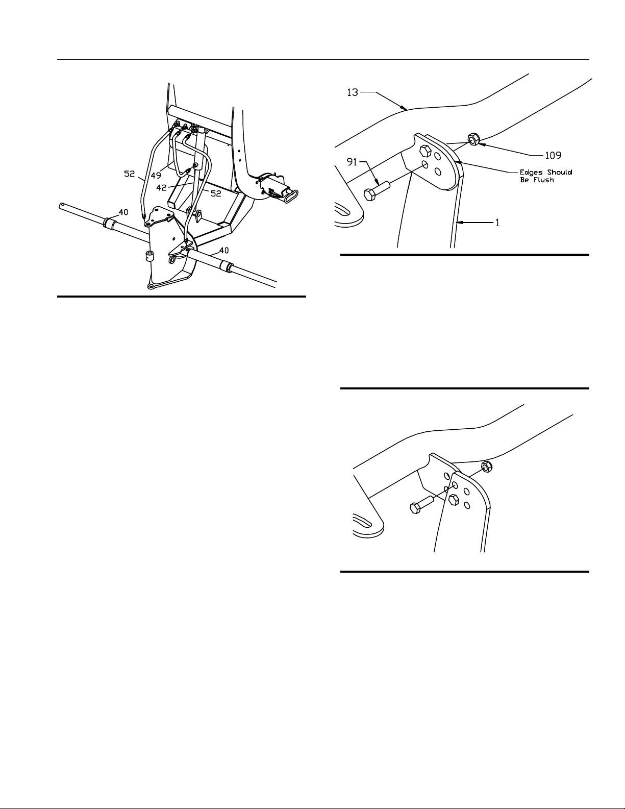
Figure 7. Assembly of Hydraulic Connections. G10013
24. Attach one end of Hydraulic Hose 49) to the
lower port of Lift Cylinder 42). Attach the
opposite end of Hydraulic Hose 49) to the center
Hydraulic Fitting 54). Tighten connection
securely.
25. Apply thread sealant compound do not use
Teflon Tape) to the threads of the 3/8” MNPT end
of HYD07042 Hydraulic Hose 52). Thread the
hose into the port on Angle Cylinder 40) and
tighten securely.
N te: Do not apply thread compound to the ¼” end of
the hose.
N te: Do not get thread compound on the end of the
hose since the compound will contaminate the
hydraulic system.
26. Attach the loose end of HYD07042 Hydraulic
Angle Hose 52) to the corresponding fitting on
the hydraulic manifold. Tighten all hydraulic
connections securely.
Figure 8. Light Bar Assembly. Standard) G10132
27. Attach Light Bar 13) to the top of Coupler
Assembly 1) using two Hex Head Cap Screws
91) and Hex Head Self Locking Nuts 109).
N te: The light bar should be positioned as close to
the Coupler Tower as possible. Only two holes will be
aligned for normal installations. Only two bolts per side
are needed to secure the light bar.
Figure 9. Light Bar Assembly Adjustment. G10131
N te: Figure 9 illustrates that the Coupler Assembly
and Light Bar have two sets of 1 inch adjustment holes
for mounting on different vehicles. These adjustment
holes may be needed in order to move the light bar
away from the vehicle’s hood.

Snowplow Assem ly Procedure
8
Figure 10. Headlight Mounting Assembly G10115
28. Insert Light Bar Seal 79) into the Light Bar and
seat it using the end of the Turn Signal 76C).
29. Attach Turn Signal 76C) into the end of Light Bar
13) using one Machine Screw 76F) and Nut
76G).
N te: Do not over tighten Machine Screw 76F).
30. Bolt Driver’s Side Headlight 76A) on to Light
Bar 13) using two bushings 76H), ½” Nuts
76D) and ½” Star Washers 76E) as shown
above.
31. Repeat Steps 28 through 30 for Passenger’s
Side Headlight 76B) and Passenger’s Side
Turn Signal 76C).
Figure 11. Secure Wiring Harness G10126
32. Secure Wiring Harness 61) to Light Bar 13)
as shown above.
33. Insert the unconnected ends of the Plow Wiring
Harness into the back of the coupler through
the rubber grommet.
34. Connect the Plow Side Wiring Harness to the
Hydraulic Valve Manifold as shown in Figure
26. HYD07044 with SmartHitch2
TM
Wiring
Diagram on page 18 of this manual.
N te: All wires need to be connected.
N te: The SmartHitch2
TM
switch is pre-wired from
the factory.
Figure 12. Assembly of Blade Guides. G10071
35. Attach Blade Guides 16) to Blade Assembly 4)
using Hex Head Cap Screws 94) and Self
Locking Nuts 115).
Electrical System Wiring Procedure
9
Electrical System Wiring
Pr cedure
WARNING!
WARNING!WARNING!
WARNING!
Before starting any Electrical Wiring Procedure
make sure that the engine is not running and that
the engine has had sufficient time to cool down.
Failure to do so may result in serious bodily injury
or death.
WARNING!
WARNING!WARNING!
WARNING!
Before starting any Electrical Wiring Procedure
make sure to disconnect the battery. Failure to
do so may result in serious bodily injury or death.
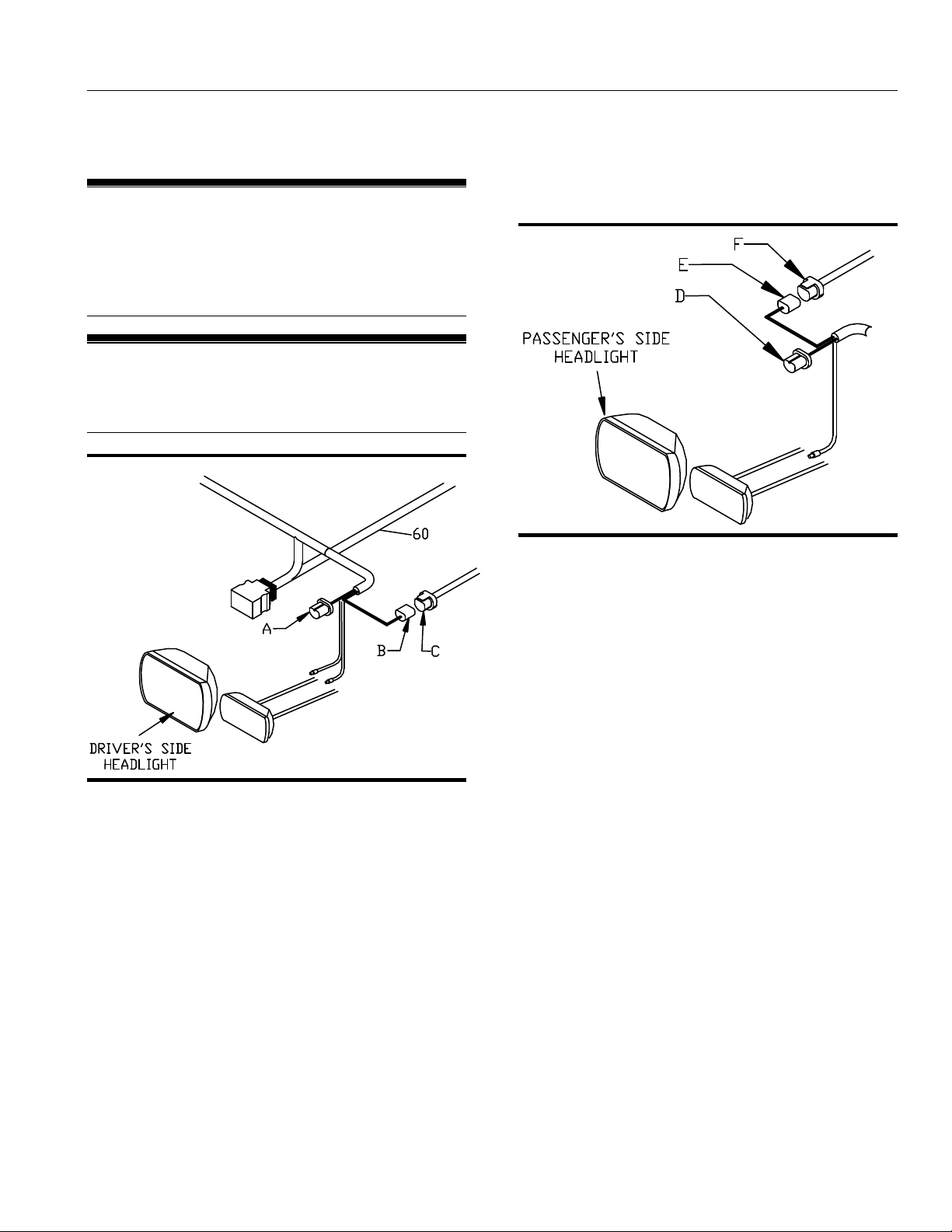
Figure 13. Driver’s Side Headlight G10140
N te: Dielectric grease should be applied to all
electrical connections.
1. Disconnect the driver’s side headlight connector
plug C) from the back of the driver’s side vehicle
headlight.
2. Connect the Blue Sealed Beam Connector A)
from Wiring Harness 60) into the back of the
driver’s side vehicle headlight.
3. Connect the Black Rubber Connector B) from
Wiring Harness 60) into the OEM Wiring Harness
C). OEM Wiring Harness C) is the vehicle
connector that was unplugged from the back of
the headlight in Step 1.
N te: If your connectors do not match the connectors
on the wiring harness or you have a four-headlight
system a Headlight Adapter Kit will be needed. If you
are installing a Headlight Adapter Kit, See “Headlight
Adapter Installation Procedure” located in this manual.
Figure 14. Passenger’s Side Headlight G10141
4. Disconnect the passenger’s side OEM Wiring
Harness F) from the back of the passenger’s side
vehicle headlight.
5. Connect the Blue Sealed Beam Connector D)
from Wiring Harness 60) into the back of the
passenger’s side vehicle headlight.
6. Connect the Black Rubber Connector E) from
Wiring Harness 60) into the OEM Wiring Harness
F). OEM Wiring Harness F) is the vehicle
connector that was unplugged from the back of
the headlight in Step 4.

Electrical System Wiring Procedure
10
Figure 15. Connecting Park and Turn G10143
N te: Some trucks require a turn signal relay kit.
7. Connect the PINK wire from Wiring Harness 60)
to the passenger’s side turn signal wire. Use the
splice connector provided to you in the hardware
kit.
8. Connect the VIOLET wire from Wiring Harness
60) to the driver’s side turn signal wire. Use the
splice connector provided to you in the hardware
kit.
9. Connect the YELLOW wire from Wiring Harness
60) to the driver’s side park light wire. Use the
splice connector provided to you in the hardware
kit.
N te: Be sure that the firewall is clear of obstructions
before drilling in Step 10.
10. Drill a 1-1/4" diameter hole through the firewall.
The hole should be located on the driver’s side, in
an easily accessible area.
Figure 16. Internal Cab Wires G10144
11. Pull the two BLACK wires H), BLACK/RED wire
I), and the 9 Pin Molex connector G) from the
engine compartment into the cab through the
1-1/4” diameter hole in the firewall.
12. Install MSC03761 Split Rubber Grommet Not
Shown) into the hole that was cut in the firewall.
13. Connect the Two Tab Connectors H) to
MSC04747 Headlight Toggle Switch 77A) as
illustrated in the figure above.
14. Choose an area of the vehicle’s dashboard for the
light toggle switch to be mounted. Clean the area
thoroughly. Allow the area to dry completely.
15. Remove the adhesive backing and apply the
switch to the clean area of the dashboard. Apply
pressure for 30 seconds.
NOTICE
Before splicing into any electrical circuit, identify
the circuit with a test lamp. Failure to test circuits
may result in vehicle damage.
NOTICE
Position the switch where it will not interfere
with driver’s ability to see and where it will not
affect the driver’s ability to operate the motor
vehicle.
Electrical System Wiring Procedure
11
16. Secure the 9 Pin Molex Connector G) and wire
loom underneath the dashboard.
17. Plug the controller into the 9 Pin Molex Connector
G).
18. Mount the plow control in a location that is
comfortable for the operator to reach, and where
the operator will not contact the control in the
event of a crash. See “V-Blade Controller
Mounting Instructions” located in this manual.)
19. Connect the BLACK/RED wire I) to a “keyed”
12V+ ignition source.
N te: This 12V+ source should only be active when
the key is in the ON position. Failure to wire to a
“keyed” source can allow a condition to occur causing
the battery to drain.
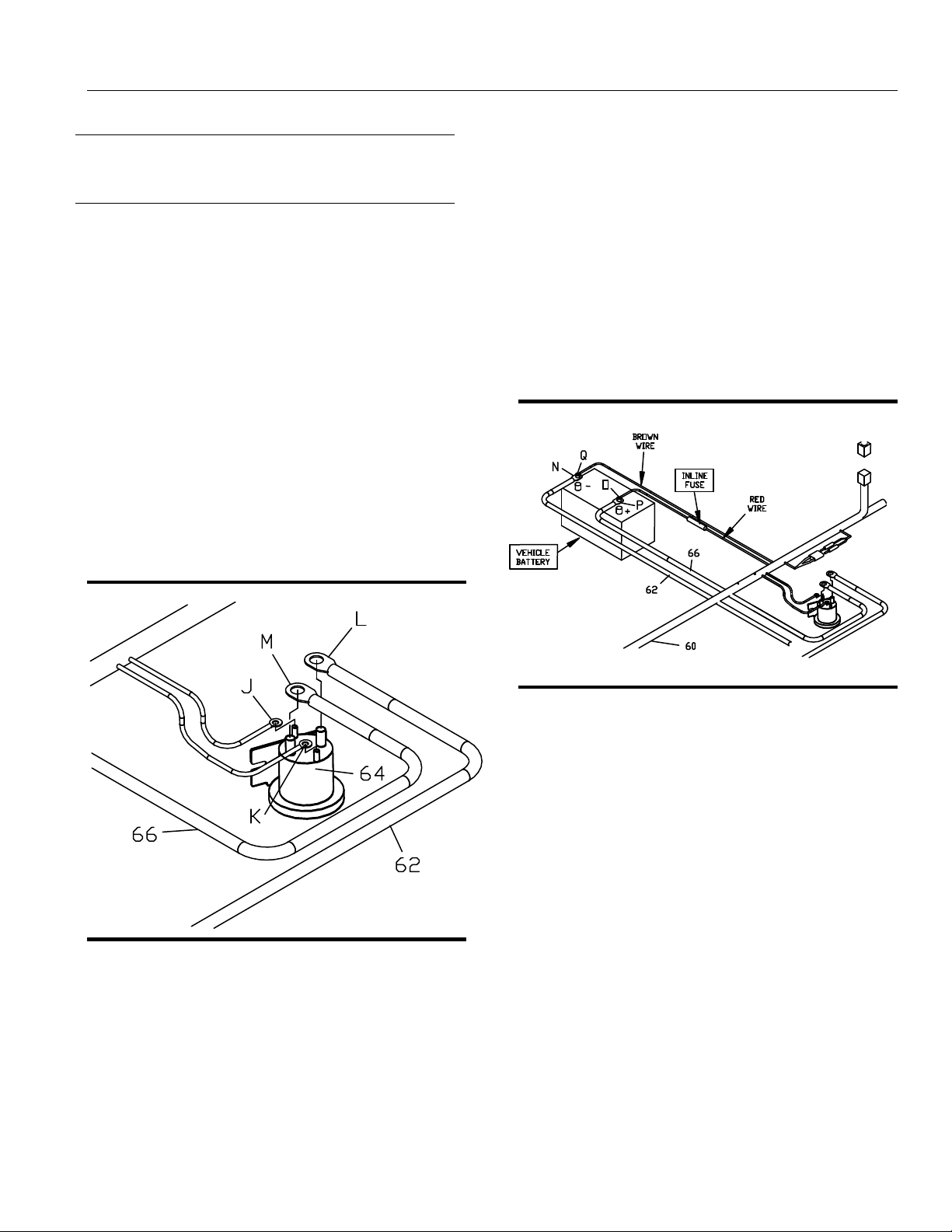
Figure 17. Solenoid Connections. G10145
20. Connect the WHITE/BLACK wire J) of Wiring
Harness 60) to the small terminal on Pump
Solenoid 64).
21. Connect the BROWN wire K) of Wiring Harness
60) to the small terminal on Pump Solenoid 64).
N te: Location of the wires on the small terminals
does not matter.
22. Attach Power Unit Solenoid 64) securely inside
the engine compartment. The Power Unit
Solenoid should be mounted in the upright
position as illustrated above.
N te: The solenoid must be installed so that the
solenoid posts do not contact the body, hood, or any
other conductive material on the vehicle.
23. Attach the eyelet end of RED Power/Ground
Cable 62) to the top of Pump Solenoid 64).
24. Connect Battery Cable 66) to the top post of
Pump Solenoid 64).
Figure 18. Battery Connections G10146
25. Attach the eyelet end N) of BLACK
Power/Ground Cable 62) to the negative battery
terminal.
26. Connect the BROWN wire Q) to the negative
battery terminal.
27. Connect the unattached end P) of Battery Cable
66) to the positive battery terminal.
28. Connect the RED Fused wire O) to the positive
battery terminal.
NOTICE
Be sure the wire loom does not interfere with the
operation of the vehicle’s pedals.

Electrical System Wiring Procedure
12
Figure 19. Vehicle Connections G10148
29. Mount the Black 15 Pin Control Harness
Connector to the lower area of the bumper using
MSC03813 Control Harness Mounting Bracket.
30. Mount the BLACK and RED 2 Pin Power Ground
Connector to the lower area of the bumper using
MSC03491 Power Ground Mounting Bracket.
N te: Installation location will vary depending on
truck.
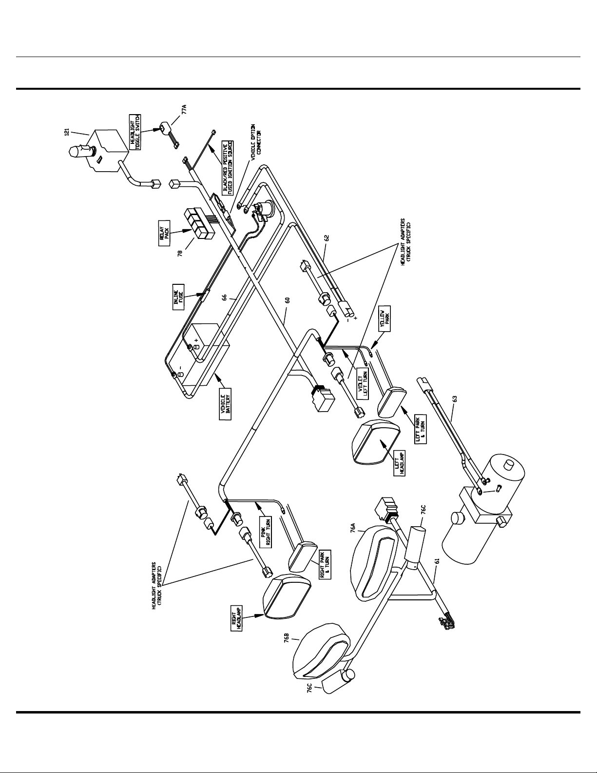
Figure 20. Relay Mounting. G10152
31. Attach the Relay Pack securely to the inside of the
engine compartment using four HDW01766 Sheet
Metal Screws. The relays should be positioned
upright as illustrated above.

Electrical System Wiring Procedure
13
Figure 21. Vehicle Option Connector G10202
NOTICE
All plow wiring should be secured within the
engine compartment in a position that provides
sufficient room so that hot or moving parts will
not be contacted. Vehicle damage could occur if
wires are not properly secured.
32. Locate vehicle option connector. Align the
connector so that the arrow on the Vehicle Option
Connector is positioned to match the vehicle it is
installed on. This is illustrated in Figure 21.
N te: If your vehicle is not listed in the above figure
use the Standard Orientation. If the Vehicle Option
Connector is not properly connected the lights on the
plow will not function correctly.
33. Secure all plow harness wiring.
34. Attach the snowplow to the vehicle. Use the
“Snowplow Mounting Procedure” that is located in
this manual to properly attach the snowplow to the
vehicle.
35. Test for the proper operation of the Headlight
Wiring Harness. Follow the procedures below.
N te: To test plow lights, the IGNITION must be in
the ON position.
• LOW BEAM (Truck Lights)
♦ Vehicle Headlight Switch – ON
♦ Low Beam Lights on Truck Indicator
♦ Plow Headlight Toggle Switch –TRUCK
RESULTS - ONLY vehicle low beam headlights should be illuminated.
• HIGH BEAM (Truck Lights)
♦ Vehicle Headlight Switch – ON
♦ High Beam Indicator Light – ON
♦ Plow Headlight Toggle Switch –TRUCK
RESULTS - Only vehicle high beam headlights should be illuminated.
• LOW BEAM (Plow Lights)
♦ Ignition - ON
♦ Vehicle Headlight Switch – ON
♦ Low Beam Lights on Truck Indicator
♦ Plow Headlight Toggle Switch - PLOW
RESULTS - ONLY plow low beam headlights should be illuminated.
• HIGH BEAM (Plow Lights)
♦ Ignition - ON
♦ Vehicle Headlight Switch – ON
♦ High Beam Indicator Light – ON
♦ Plow Headlight Toggle Switch – PLOW
RESULTS - Only plow high beam headlights should be illuminated.
• TURN SIGNALS (Plow nd Truck)
♦ Left Turn Signal Indicator – ON
RESULTS - Both Left Plow and Left Truck turn signal bulbs should
be flashing.
♦ Right Turn Signal Indicator – ON
RESULTS - Both Right Plow and Right Truck turn signal bulbs
should be flashing.
• P rk Lights (Plow nd Truck)
♦ Park Lights on Vehicle – ON
RESULTS - All four, Left Plow, Right Plow, Left Truck, and Right
Truck Park Lights should be on.
N te: If any of the lights are not working properly, re-
check the wiring against the “Electrical Wiring
Diagram” located in this manual and make any
necessary corrections.

Headlight Adapter Installation Procedure
14
Headlight Adapter Installati n
Pr cedure
Figure 22. Single Headlight Adapter Connections G10149
N te: This is a general diagram for most 2-headlight
vehicles. All vehicles and headlight adapters may not
be identical. Installation will be very similar.
1. Disconnect the OEM Headlight Connector Plug
A) from the back of the vehicle headlight.
2. Connect one end of Headlight Adapter 73A) into
the back of the vehicle headlight.
3. Connect the Black Rubber Female Socket B) of
Headlight Adapter 73A) into the plow wiring
harness.
4. Connect the Blue Sealed Beam Connector C) of
Headlight Adapter 73B) into the plow wiring
harness.
5. Connect the opposite end of Headlight Adapter
73B) into the OEM Headlight Connector Plug A).
6. Repeat Steps 1 through 5 for the opposite side
headlight.
N te: In some older vehicles it is not necessary to
pull power from both sides of the headlights. In this
case only three adapters will be needed. Follow the
Headlight Adapter Installation Instructions that are
packaged with the Headlight Adapter Kit.
7. Continue with the Step 7 of “Electrical System
Wiring Procedure” located in this manual.
Figure 23. Dual Headlight Adapter Connections G10151
N te: This is a general diagram for most 4-headlight
vehicles. All vehicles and headlight adapters may not
be identical. Installation will be very similar.
1. Disconnect OEM Headlight Connector Plugs A
and D) from the back of the vehicle headlight.
2. Connect two ends of Headlight Adapter 73A) into
the back of the vehicle headlights.
3. Connect the Black Rubber Female Socket B) of
Headlight Adapter 73A) into the plow wiring
harness.
4. Connect the Blue Sealed Beam Connector C) of
Headlight Adapter 73B) into the plow wiring
harness.
5. Connect the opposite end of Headlight Adapter
73B) into the OEM Wiring Harness A).
6. Grease, tuck, and secure OEM Connector Plug
D). This connector is not used.
7. Repeat Steps 1 through 6 for the opposite side
headlight.
8. Continue with the Step 7 of “Electrical System
Wiring Procedure” located in this manual.

Electrical System Wiring Schematic (Plow Side)
15
Figure 24. Electrical System Wiring Schematic Plow Side) G10271
Electrical System Wiring Schematic (Truck Side)
16
Figure 25. Electrical System Wiring Schematic Truck Side) G10272
Electrical System Wiring Diagram
17
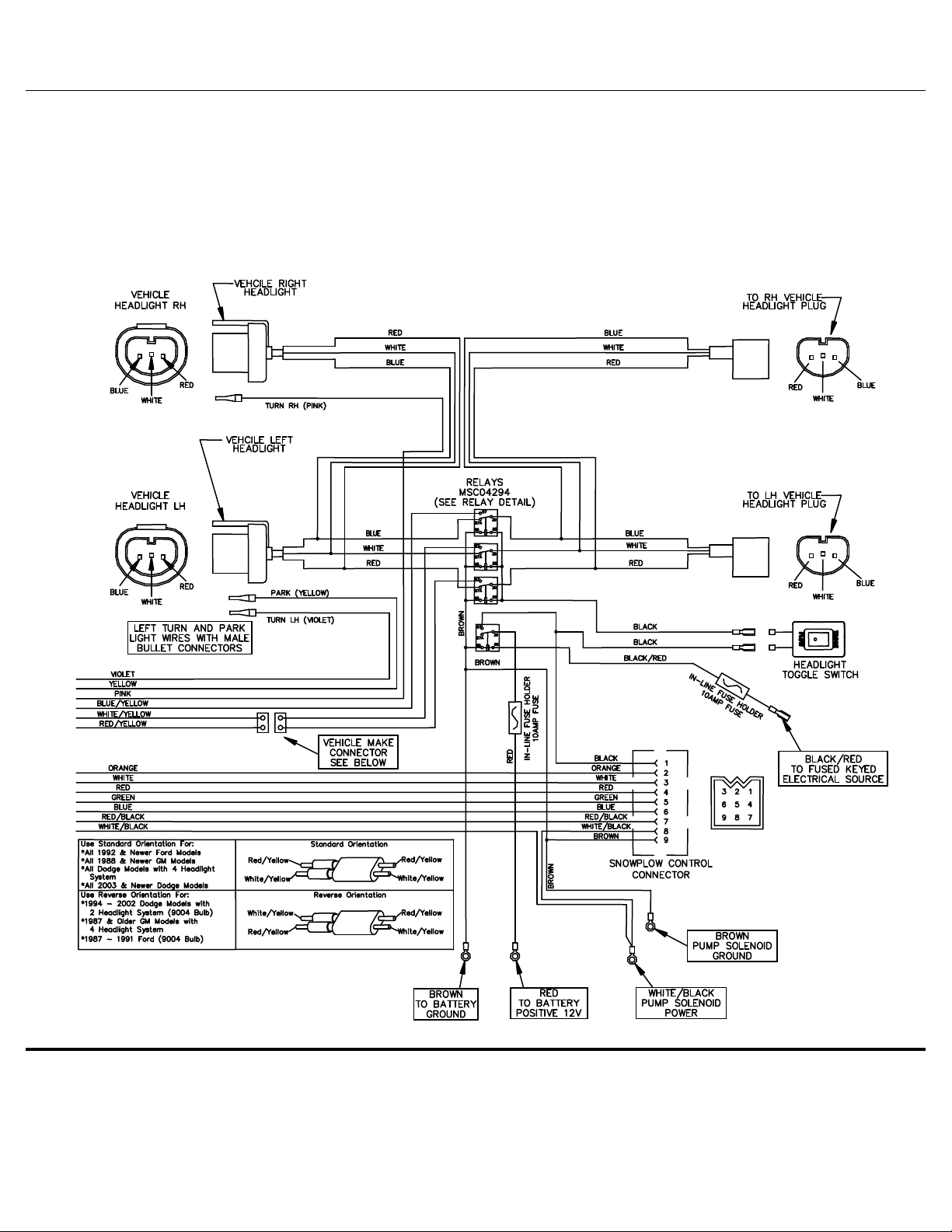
Figure 26. Electrical System Wiring Diagram G10134
SmartHitch 2
TM
Wiring Diagram
18
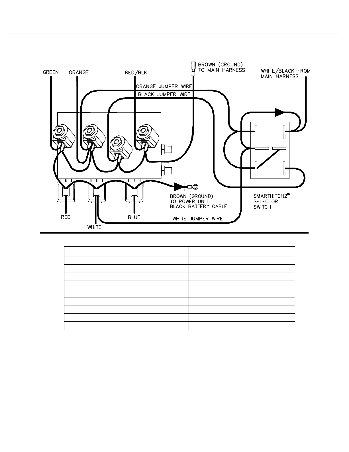
Figure 27. HYD07044 with SmartHitch2
TM
Wiring Diagram G10445
Wire C l r Wire Functi n
Green Right Wing In
Red Right Wing Out
White Lift
Orange Lower
Red/Black Left Wing In
Blue Left Wing Out
Black SmartHitch2
TM
12V)
White/Black Pump Solenoid
Brown Ground
Hydraulic Valve Assem ly Parts List
19
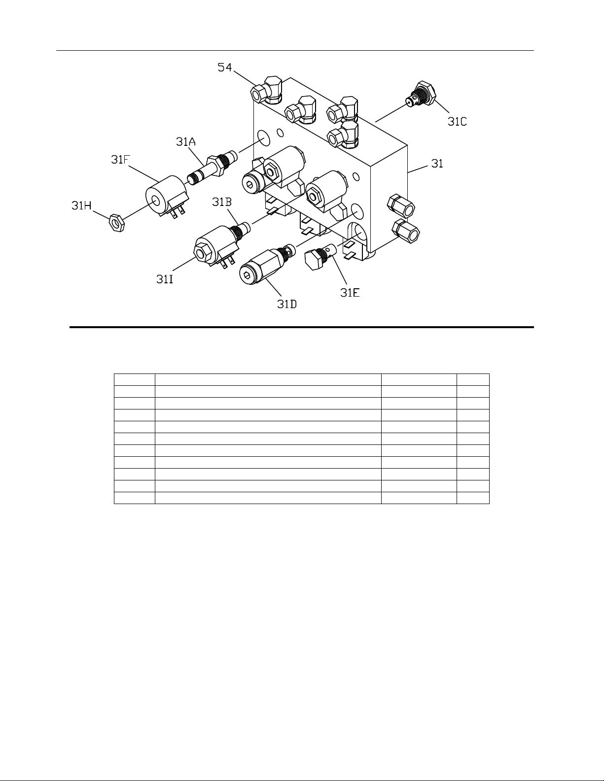
Figure 28. Hydraulic Valve Manifold Assembly.
G10000
Ref. Descripti n Part Number Qty
31 Valve Manifold, RT3 V-Blade w/ SmartHitch2
TM
HYD07044 1
31A Valve, Lift / Angle HYD01637 6
31B Valve, SmartHitch2
TM
Attach HYD07047 1
31C Valve, Flow Control HYD07048 1
31D Valve, Relief V-Blade 2800psi) HYD01639 2
31E Valve, Check HYD01640 4
31F Valve Coil HYD01638 7
31H Coil Nut HYD07059 6
31I Coil Nut SmartHitch2
TM
Valve) HYD07060 1
54 Hydraulic Swivel Fitting HYD01620 4
RT3 Headlight Aiming Pr cedure
20
Headlight Aiming
Pr cedure
NOTICE
The installer of these snowplow lights must
certify that installation conforms to applicable
Federal otor Vehicle Safety Standards.
1) Place the vehicle on a level surface 25 feet in
front of a matte-white screen, such as a garage
door. The screen should be perpendicular to both
the ground and the vehicle.
2) The vehicle should be equipped for normal
operation. The snowplow blade should be in place
and in the raised position.
3) Below are some points listed by the Society of
Automotive engineers SAE) pertinent to headlight
aiming. These points can be found in publication
#SAEJ5991D.
Preparation for Headlight Aim or Inspection
Before checking beam aim, the inspector shall:
• Remove ice or mud from under fenders.
• See that no tire is noticeably deflated.
• Check vehicle springs for sag or broken
leaves.
• See that there is no load in the vehicle other
than the driver.
• Check functioning of any “level-ride” controls.
• Clean lenses and aiming pads.
• Check for bulb burnout, broken mechanical
aiming pads, and proper beam switching.
• Stabilize suspension by rocking vehicle
sideways.
4) Mark or tape) the vehicle centerline of the
headlights and the vehicle itself on the screen.
Mark the horizontal centerline of the headlights on
the screen distance from ground to headlight
centers).
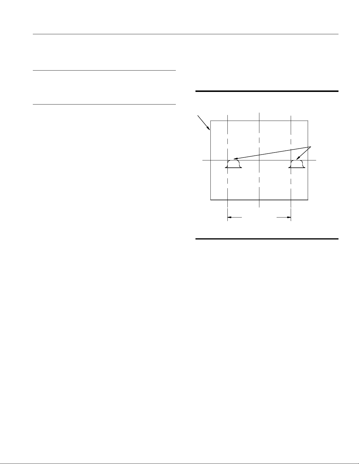
Figure 29. Headlight Aiming Procedure G10153
5) The correct visual aim for Type 2 headlights is
with the top edge of the high intensity zone of the
lower beam below the horizontal centerline and
the left edge of the high intensity zone on the
vertical centerline. See diagram above.
25' From Headlights
Screen Located
Align With Vehicle
Centerline
of Right Headlight
Vertical Centerline Ahead
High Intensity Zones
For Type 2 (Sealed Beam)
Headlights on Low Beam
Headlight Centers
Distance Between
Table of contents
Other BOSSCO Snow Blower manuals


Popular Snow Blower manuals by other brands


EINHELL
EINHELL BSF 55 operating instructions

Western
Western UltraMount MIDWEIGHT installation instructions

Toro
Toro Flex-Force Power System 31853 Operator's manual

Ariens
Ariens Sno-Thro 920021 compact 24 Operator's manual

Buhler
Buhler Farm king FK311 owner's manual

Simplicity
Simplicity 869 owner's manual