BOSSCO Snowrator MAG User manual

FormNo.MSC23901RevA
Owner'sManual
48inSnowthrowerKit
SnowratorMAG
PartNo.STX24410—SerialNo.400000000andUp
Registeratwww.bossplow.com.
OriginalInstructions(EN)*MSC23901*
BOSSProductslimitedconsumerwarrantyandBOSS
Productscommercialwarrantypoliciesarelocatedat
www.bossplow.com.
Patentswww.ttcopats.com.
Introduction
Note:ThissnowthowerattachestotheSnowrator
MAG.
ThesnowthrowerisintendedtobeusedonaBOSS
stand-on,multi-purposemachine.Thisattachmentis
usedtoremovesnowfrompavedorgravelsurfaces,
suchasdrivewaysandsidewalks,andothersurfaces
fortrafconresidentialorcommercialproperties.
Usingthisproductforpurposesotherthanitsintended
usecouldprovedangeroustoyouandbystanders.
Readthisinformationcarefullytolearnhowtooperate
andmaintainyourproductproperlyandtoavoid
injuryandproductdamage.Youareresponsiblefor
operatingtheproductproperlyandsafely.
Visitwww.bossplow.comforproductsafetyand
operationtrainingmaterials,accessoryinformation,
helpndingadealer,ortoregisteryourproduct.
Wheneveryouneedservice,genuineBOSSparts,or
additionalinformation,contactanAuthorizedBOSS
DealerorBOSST echnicalService(1-800-286-4155)
andhavethemodelandserialnumbersofyour
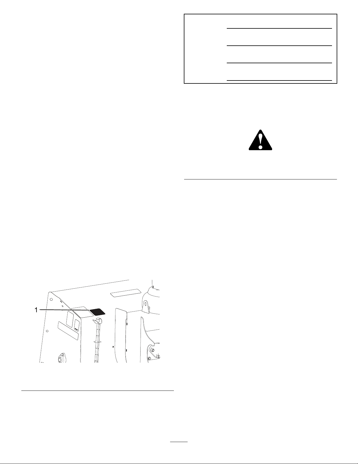
productready.Figure1identiesthelocationofthe
modelandserialnumbersontheproduct.Writethe
numbersinthespaceprovided.
g383239
Figure1
1.Modelandserialnumberlocation
Date
Purchased
ModelNo.
SerialNo.
BladeCrate
SerialNo.
Thismanualidentiespotentialhazardsandhas
safetymessagesidentiedbythesafety-alertsymbol
(Figure2),whichsignalsahazardthatmaycause
seriousinjuryordeathifyoudonotfollowthe
recommendedprecautions.
g000502
Figure2
1.Safety-alertsymbol
Thismanualuses2wordstohighlightinformation.
Importantcallsattentiontospecialmechanical
informationandNoteemphasizesgeneralinformation
worthyofspecialattention.
©2022—BOSSProducts
P .O.Box787
IronMountain,MI498012
Contactusatwww.bossplow.com.
PrintedintheUSA
AllRightsReserved

Contents
Safety.......................................................................3
Preparation.........................................................3
Operation............................................................3
SafetyandInstructionalDecals..........................4
Setup........................................................................5
MountingtheAttachment....................................5
RoutingtheHydraulicHoses..............................6
ProductOverview.....................................................9
Controls.............................................................9
Operation................................................................10
OperatingtheSnowthrower..............................10
RemovingtheAttachment................................10
OperatingTips..................................................11
Maintenance...........................................................12
RecommendedMaintenanceSchedule(s)...........12
.........................................................................12
Maintenance........................................................12
CheckingtheChainTension.............................12
OilingtheChain................................................12
ReplacingtheCuttingEdge..............................13
GreasingtheAttachment..................................13
AdjustingtheSkids...........................................13
Storage...................................................................15
StoringtheAttachment.....................................15
RemovingtheAttachmentfromStorage...........15
Troubleshooting......................................................16
Safety
Improperuseormaintenancebytheoperatoror
ownercanresultininjury.Toreducethepotential
forinjury,complywiththesesafetyinstructions
andalwayspayattentiontothesafety-alert
symbol,whichmeans:Caution,Warning,or
Danger—personalsafetyinstruction.Failureto
complywiththeinstructionmayresultinpersonal
injuryordeath.
Preparation
•ReadtheOwner’sManualbeforeoperatingor
servicingtheattachment.
•Ensurethatonlytrainedpersonnelinstallsand
performsmaintenanceontheequipmentand
hydrauliccomponents.
•Alwayswearappropriatepersonalprotective
equipmentwhenloading,unloading,andservicing
theattachment.
Operation
•Usea500kg(1/2ton)minimumliftingdeviceto
moveheavycomponents.
•Donotexceed8km/h(5mph)whileoperating.
•Neverputanypartofyourbodybetweenthe
attachmentandthevehicle.
•Wearappropriateclothing,includinghearingand
eyeprotection,protectivegloves,andsubstantial,
slip-resistantfootwear.Tiebacklonghair,secure
looseclothing,anddonotwearloosejewelry.
•Whentransportingthemachine,ensurethatitis
properlysecured.Instructionsareavailableat
www.bossplow.com.
•Whentransportingthevehicle,positionthe
attachmentsothatitdoesnotblockyourvision
orheadlights.
•Alwayslowertheattachmentwhenthevehicleis
notinuse.
•Donotoperatethemachinewhileill,tired,or
undertheinuenceofalcoholordrugs.
•RefertotheOwner’sManualforproperparking
procedures.
•Turnthevehicleandattachmentoffbeforelling,
servicing,orcleaningit.
•Donotclimbintoorrideontheattachment.
•Keepyourhands,feet,andclothingawayfrom
movingpartsandmountingpoints.
•Useyourfullattentionwhileoperatingthe
machine.Donotengageinanyactivitythat
3
causesdistractions;otherwise,injuryorproperty
damagemayoccur.
•Donotoperatetheattachmentnearbystanders.
SafetyandInstructionalDecals
Safetydecalsandinstructionsareeasilyvisibletotheoperatorandarelocatednearanyarea
ofpotentialdanger.Replaceanydecalthatisdamagedormissing.
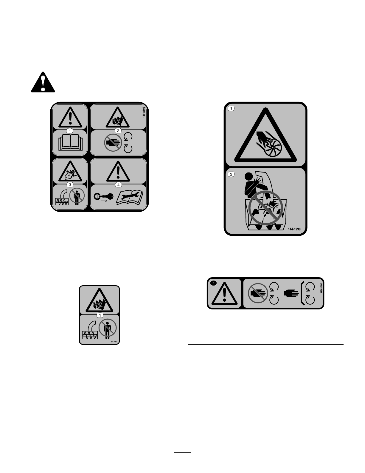
decal139-8895
139-8895
1.Warning—readthe
Operator’sManual.
3.Thrownobject
hazard—keepbystanders
away.
2.Cutting/dismemberment
hazardoffoot,
auger—stayawayfrom
movingparts.
4.Warning—removethekey
fromtheignitionbefore
servicingthemachine.
decal139-8896
139-8896
1.Cutting/dismembermenthazardoffoot,auger—keep
bystandersaway.
decal144-1299
144-1299
1.Cutting/dismemberment
hazardofhand;impeller
2.Donotplaceyourhandin
thechute.
decalmsc27245
MSC27245
1.Warning—stayawayfrommovingparts;keepallguards
andshieldsinplace
4

Setup
MountingtheAttachment
1.Parkthemachineonalevelsurface.
2.Pullthecouplerpinsoutwardandrotate90°to
lockinthedisengagedposition.
g373475
Figure3
3.Makesurethatthehydraulichosesdonotblock
theattachmentpoint.
4.Startthemachine.
5.Slowlydriveforwarduntilthecouplermeetsthe
attachmenthooks.Raisethecouplertohook
itontotheattachment.
g383235
Figure4
6.Rotatethecouplerpin90°sothatitengages
withtheattachmentassembly.
Note:Ensurethatthecouplerpinalsoinserts
throughtheholeinthepinchannelonthe
coupler.
g373477
Figure5
7.Lowertheattachmentcoupleruntilthe
attachmentrestsontheground.
5

RoutingtheHydraulicHoses
1.Shutoffthemachineengine,waitforallmovingpartstostop,ensurethattheparkingbrakeisengaged,
andremovethekey.
2.Routethehydraulichoses.
Note:Whenchangingattachmentsonthemachineyoumayneedtorelievestoredhydraulicpressureby
slightlylooseninghydrauliclinesonthesnowthrowerorwigglethejoysticksonmachine.
g383236
Figure6
6

g383237
Figure7
g383238
Figure8
7
3.Gatherthehosesandsecuretheminthehosestraponthemachine.
g385655
Figure9
4.Startthemachine.
5.Usethecontrolstomovetheattachmentinalldirectionstocyclethehydraulicuid.
6.Lowertheattachmentandshutoffthemachine.
7.Checkandllthehydraulicuid;refertothemachineOwnersManual.
WARNING
Hydraulicuidescapingunderpressurecanpenetrateskinandcauseinjury.
•Ifhydraulicuidisinjectedintotheskin,itmustbesurgicallyremovedwithinafew
hoursbyadoctorfamiliarwiththistypeofinjury.Gangrenemayresultifthisisnot
done.
•Keepyourbodyandhandsawayfrompinholeleaksornozzlesthatejecthigh-pressure
hydraulicuid.
•Usecardboardorpapertondhydraulicleaks.
•Safelyrelieveallpressureinthehydraulicsystembeforeperforminganyworkonthe
hydraulicsystem.
•Makesurethatallhydraulic-uidhosesareingoodcondition,andallthatthehydraulic
connectionsandttingsaretightbeforeapplyingpressuretothehydraulicsystem.
8
ProductOverview
Controls
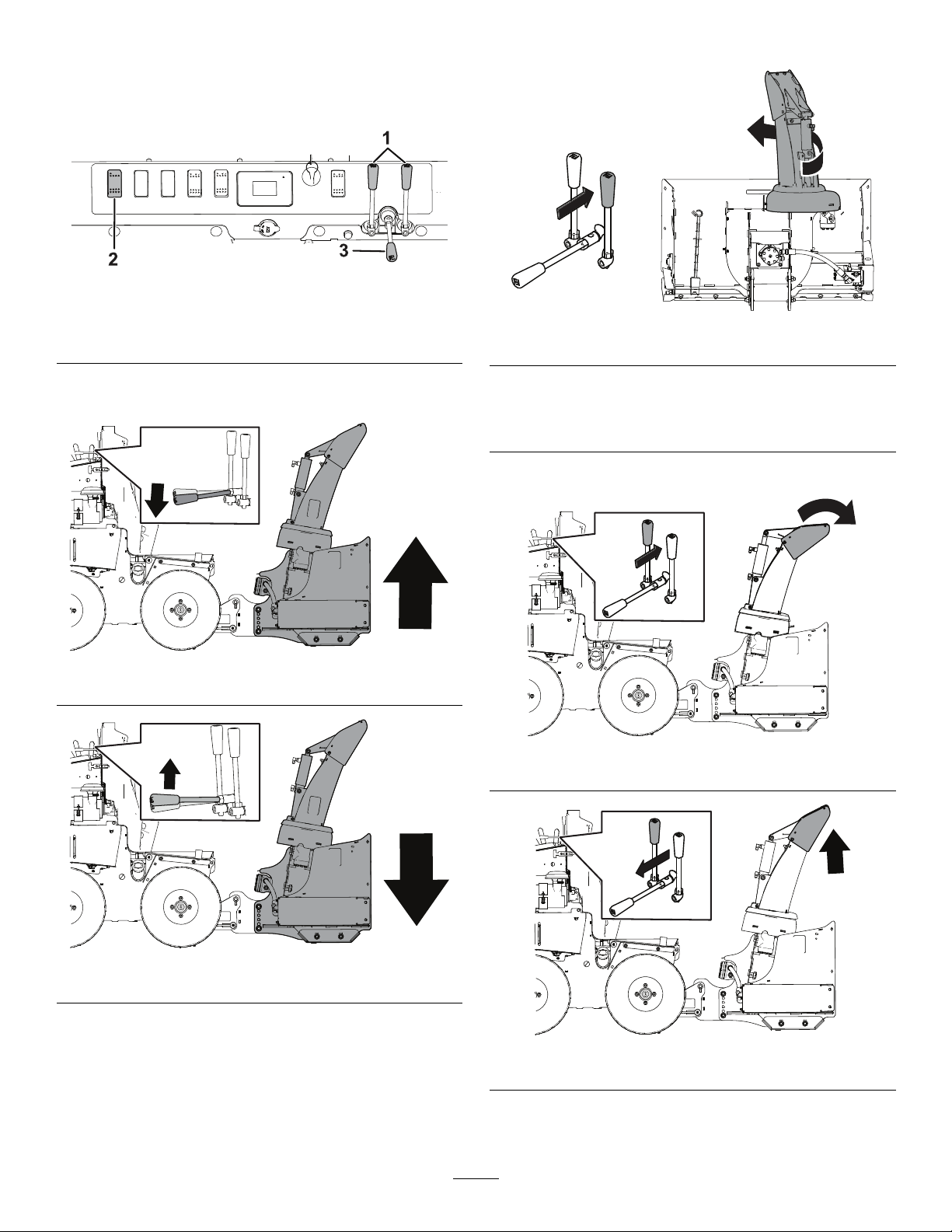
g383364
Figure10
1.Anglelevers3.Attachmentcouplerlever
2.Engagetheattachment
•Usetheattachmentcouplerlevertoraiseorlower
theattachment.
g383344
Figure11
g383342
Figure12
•Usetherightanglelevertorotatethechute.
g383346
Figure13
g383347
Figure14
•Usetheleftanglelevertomovethechutedeector.
g383343
Figure15
g383345
Figure16
9
Operation
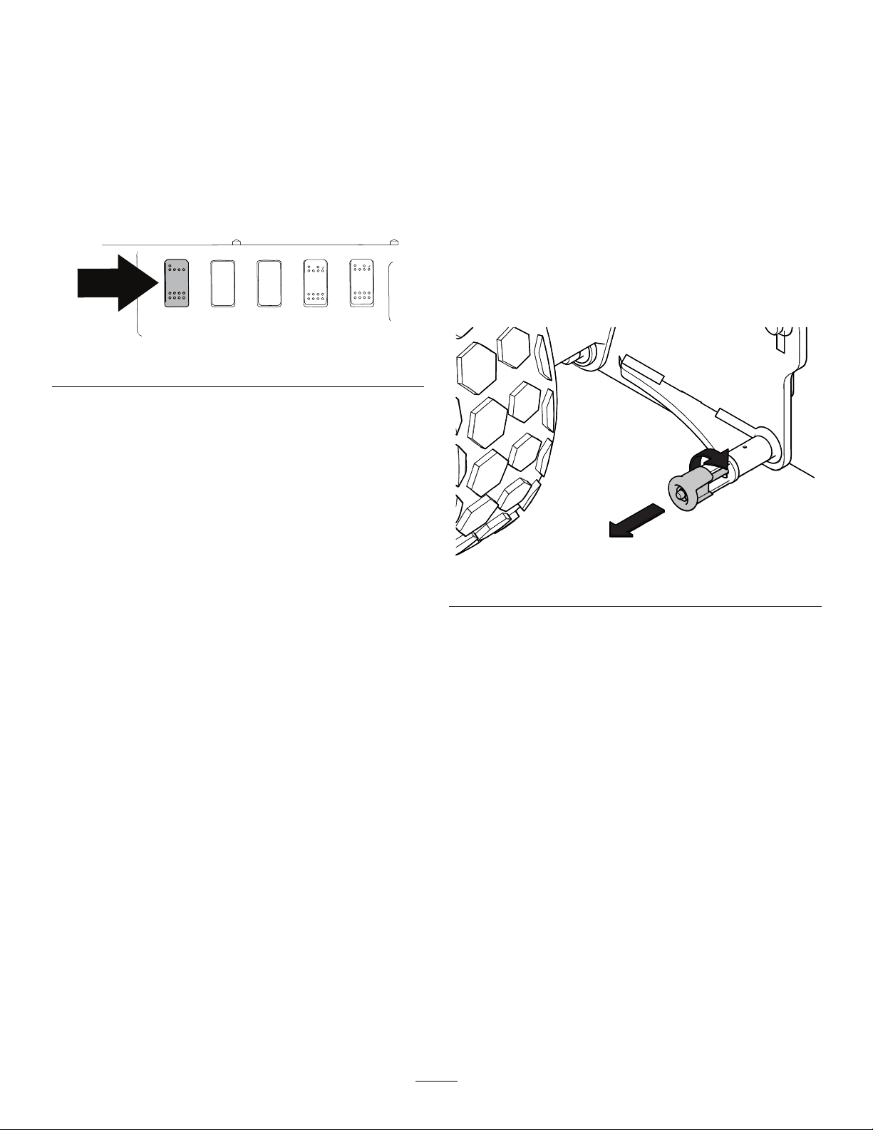
OperatingtheSnowthrower
Important:Raisethesnowthrowerwhen
transportingit.
1.Startthemachine.
2.Pushthetopofthehighowengageswitchto
spinthebladesintheforwardposition.
g383377
Figure17
Note:Thebladesshouldspincounterclockwise
whenviewedfromtheleftsidefromthe
operatingposition.Ifthebladesspininthe
wrongdirection,switchthecouplersonthe
hydraulichosesconnectedtothehighow
hydraulicports.
Note:Toassistinremovingaclog,pushthe
bottomofthehighowengageswitchtospin
thebladesinreverse.
RemovingtheAttachment
1.Stopmachineonalevelsurface.
2.Lowertheattachmentuntiltheedgeis1-2
inchesfromtheground.
3.Shutofftheengine,waitforallmovingpartsto
stop,engagetheparkingbrake,andremove
thekey.
Note:Ifyouareremovingtheattachmentfor
storage,allowthemachinetowarmtotheindoor
temperaturebeforeshuttingofftheengine.
4.Disconnectthehydraulics.
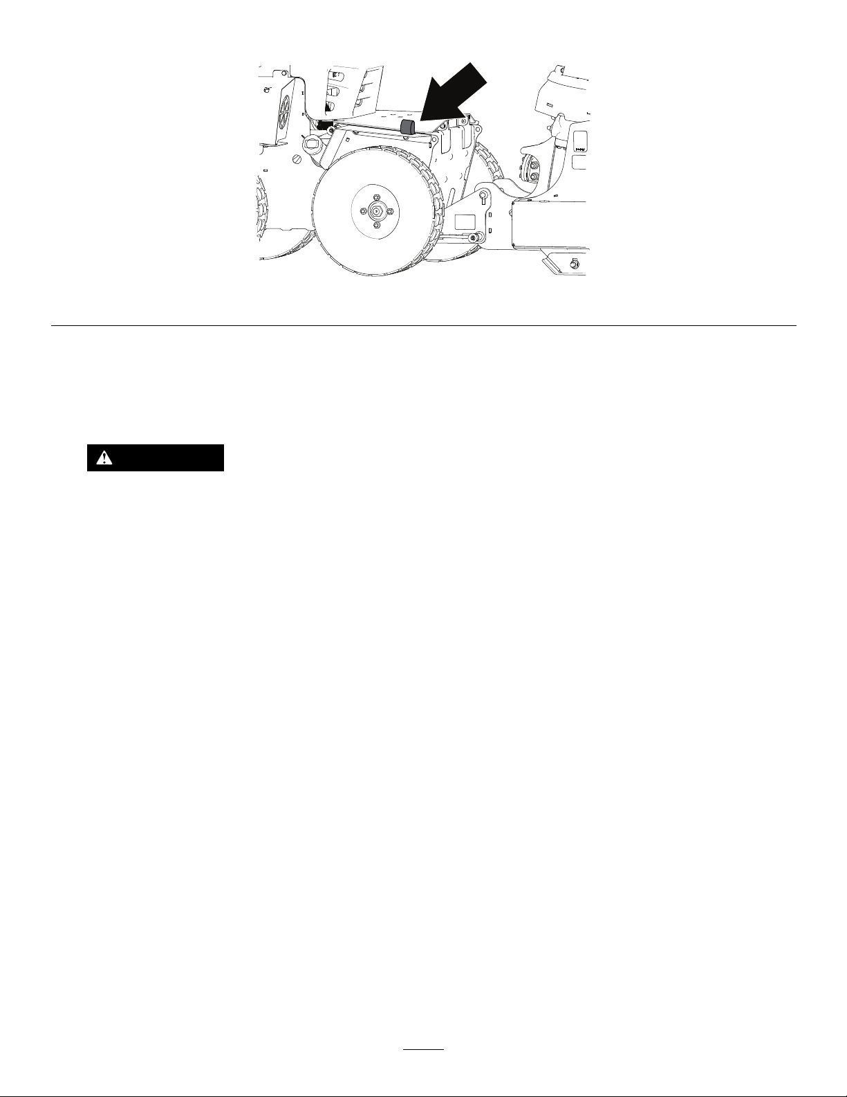
5.Pullthecouplerpinsandturnit90°untilthe
attachmentisdisconnectedfromthemachine.
g373484
Figure18
6.Startmachine,lowerattachmentcoupler,and
slowlybackawayfromtheattachment.
7.Arrangethehydraulichosesanddisconnectsso
thattheyarenotrestingontheground.
Note:Wrapthehosestogetherandstickthem
downthechuteforstorage.
10

OperatingTips
•Becomefamiliarwiththeareayouareoperating
theattachment;hiddenobstructionssuchas
curbsandpipescandamageyourattachmentor
machine.
•Lowertheattachmentwhennotinusetoprevent
possibleinjury.
•Alwaysoperatethemachineatasafespeedin
caseyouhithiddenobstructions.
•Whentransportingthemachine,donotblockyour
visionwiththeattachment.
•Thesnowthowerwillcleanbetterwhenthelift
valveisintheoatposition.
•Machinetractionisimprovedwhentheattachment
isliftedslightlyorifitisnotintheoatposition.
•Loosentheskids,putthemachineinoat,then
tightentheskidstogetthemaximumscraping
performance.
•Formoretips,visitwww.bossplow.com.
11
Maintenance
RecommendedMaintenanceSchedule(s)
MaintenanceService
IntervalMaintenanceProcedure
Aftertherst2hours•Tightenallhardware.
Beforeeachuseordaily
•Checkthehydrauliccylinders.
•Checkthehydrauliclinesandhoses.
•Checkallfasteners,pins,retainers,nuts,andbolts.
•Checkthecuttingedgeforwear.
•Oilthechain.
Every50hours•Greasetheattachment.
Every100hours•Checkthechaintension.
Beforestorage
•Lightlysandandusetouch-uppaintonpaintedareasthatarescratched,chipped,
orrusted.
•Oilthechain.
•Greasethehydrauliccylinderrods.
•Lightlysandandusetouch-uppaintonpaintedareasthatarescratched,chipped,
orrusted.
Maintenance
•Checkthehydrauliclinesandhosesdailyfor
leaks,kinkedlines,loosemountingsupports,wear,
loosettings,weatherdeterioration,andchemical
deterioration.Makeallnecessaryrepairsbefore
operating.
•Checkthehydrauliccylindersdailyforleaks,rust,
orpittingontherods.Makeallnecessaryrepairs
beforeoperating.
•Checkthecuttingedgedailyforwear.Replacethe
cuttingedgeifitisworndown.
•Checkallfasteners,pins,retainers,nuts,andbolts
dailytoensurethattheyaresecure.Torquethem
totheappropriatevalueiftheyareloose.
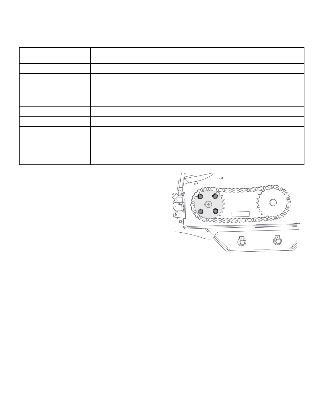
CheckingtheChainTension
ServiceInterval:Every100hours
1.Removethechainguard.
2.Loosenthe4motorbolts.
g386209
Figure19
3.Pullbackthemotorandholdinplace.
4.Tightenthe4bolts.
5.Installtheguard.
OilingtheChain
ServiceInterval:Beforeeachuseordaily
Beforestorage
UseBossSnowratorHydraulicFluidorSAE20oil.
1.Raisetheattachmentallthewayupusingthe
hydrauliccontrols.
2.Removetherubberplugonthechainhousing
andinsertitintothehousingwiththecupside
up.
12
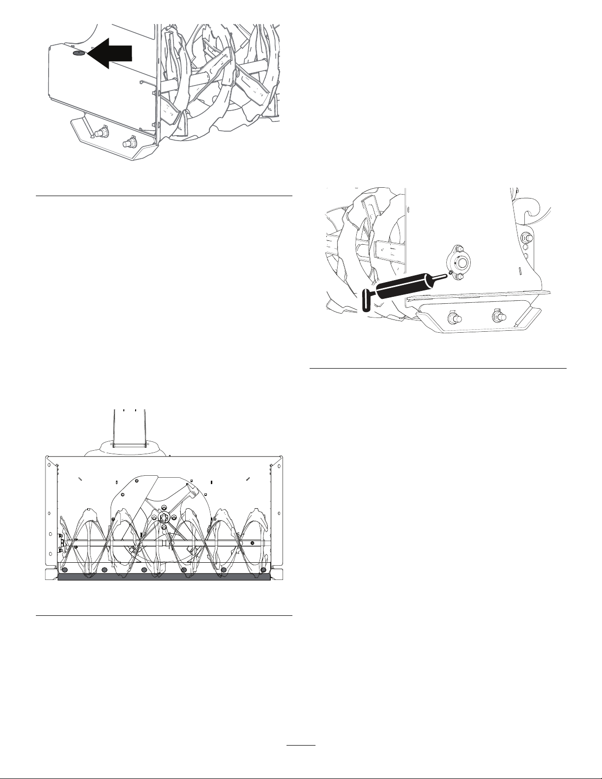
g385752
Figure20
3.Filltherubberplugwithoil.
4.Startthemachineandrunitatlowidle.
5.Operatethesnowthroweratlowidleuntilthe
plugisoutofoil.
6.Removetheplugandinstallitwiththeatface
uptopreventitfromllingwithdebrisduring
operation.
ReplacingtheCuttingEdge
Note:Replacementhardwareisavailablethroughan
AuthorizedBossDealerorBossTechnicalService.
1.Removethehardwareholdingthecuttingedge
totheblade.
g385776
Figure21
2.Flipthecuttingedgeover.
Note:Ifthecuttingedgehasalreadybeen
ipped,discarditanduseanewedge.
3.Installnewcuttingedgewithexistinghardware.
Torqueto101N·m(75ft-lbs).
GreasingtheAttachment
ServiceInterval:Every50hours
1.Parkthemachineonalevelsurfaceandshut
offtheengine.
2.Cleanthegreasettingwitharag.
3.Connectagreaseguntoeachtting.
4.Pumpgreaseintothettingsuntilgreasebegins
tooozeoutofthebearings(approximately3
pumps).
5.Wipeupanyexcessgrease.
g383365
Figure22
AdjustingtheSkids
Checktheskidstoensurethattheaugerdoesnot
contactthepavedorgravelsurface.Adjusttheskids
asneededtocompensateforwear.
Ifthepavementiscracked,rough,oruneven,adjust
theskidstoraisethepolyedges.Forgravelsurfaces,
adjusttheskidsfurtherdowntopreventthemachine
frompickinguprocks.
LoweringtheSkids
1.Parkthemachineonalevelsurface.
2.Shutofftheengine,removethekey,andwait
forallmovingpartstostopbeforeleavingthe
operatingposition.
3.Loosenthenutsthatsecurebothskidstothe
augersidesuntiltheskidsslideupanddown
easily.
Important:Supporttheaugerbladesabove
thegroundusingtheskids.
4.Movetheskidsdownuntiltheyareevenwith
theground.
5.Firmlytightenthenutsthatsecurebothskids
totheaugersides.
13

Note:Toquicklyadjusttheskidsiftheyloosen,
restthepolyedgeonthepavement,thenadjust
theskidsdown.
g383363
Figure23
RaisingtheSkids
1.Parkthemachineonalevelsurfaceandraise
theattachment.
2.Shutofftheengine,removethekey,andwait
forallmovingpartstostopbeforeleavingthe
operatingposition.
3.Loosenthenutsthatsecurebothskidstothe
augersidesuntiltheskidsslideupanddown
easily.
Important:Supporttheaugerbladesabove
thegroundusingtheskids.
4.Placeaboard,ofyourdesiredthickness,under
thepolyedgeofthesnowthrower.
g385838
Figure24
5.Startthemachine,putitintheoatposition,and
tightentheskids.
14

Storage
StoringtheAttachment
1.Beforelongtermstorage,washtheattachment
withmilddetergentandwatertoremovedirtand
grime.
2.Placethechuteintheupwardsposition.
3.Checktheconditionofthescraperblade.
4.Checkandtightenallbolts,nuts,andscrews.
Repairorreplaceanydamagedorwornparts.
5.Greaseanyexposedmetalonthehydraulic
cylinderrods.
6.Greasethechuteanglegear.
7.Lightlysandandusetouch-uppaintonpainted
areasthatarescratched,chipped,orrusted.
Note:Thepaintontheimpellerhousing,inside
ofchute,andimpellerdoesnotneedtobe
painted,applypenetratingoiltothesesurfaces.
8.Storetheattachmentinaclean,drygarageor
storagearea.Coverittoprotectitandkeepit
clean.
RemovingtheAttachment
fromStorage
1.Checkthetorqueofallfasteners;tightenas
necessary.
2.Checkthehydrauliclinesandhosesforcracks
orleaks.
3.Checkthecuttingedgeforwear.
4.Lightlysandandusetouch-uppaintonpainted
areasthatarescratched,chipped,orrusted.
5.Attachtheattachmenttothemachine;referto
yourmachineOperator’sManual.
6.Movetheattachmentthroughitsrangeofmotion
tocheckthehydrauliccylinderrods.
15

Troubleshooting
ProblemPossibleCauseCorrectiveAction
1.Thechainbroke.1.Checkthechainforbreak.Replace
anydamagedcomponents.
2.Theaugercouldbejammed.2.Checktheaugerfordebris.
3.Theaugerboltsarebad.3.Inspecttheaugerbolts.Replaceany
damagedcomponents.
Theaugerisnotmovingbuttheimpeller
stillrotates.
4.Asprocketkeycouldbemissingor
bad.
4.Inspectthesprocketkeys.Replace
anydamagedcomponents.
Theimpellerisnotmovingbuttheauger
stillrotates.
1.Debrisiscaughtintheblades.1.Checktheimpellerfordebris.
1.Thehydraulicuidlevelislow.1.Checkthehydraulicuidlevel;referto
yourSnowratorMAGOwner'sManual.
2.Thehydraulicuidlevelislowandthe
SnowratorMAGwasstoppedquickly.
2.SlowtheSnowratorMAGgradually
beforecomingtoastopwhenthe
hydraulicuidislow.
3.Thepressurereliefvalveisbad3.Checkthepressurereliefvalve,
locatedontheSnowratorMAGtraction
unit.Ifthevalveiscontaminated,clear
orreplaceit.
4.Acylinderorhoseisbad.4.Checkthecylinders,hoses,andall
ttingsforleaks.Tightenanyloose
connections.Replaceanydamaged
components.
Theattachmentisnotfunctioningorthey
moveslowly.
5.Thehydrauliccouplingsarenot
attachedtothevehicle.
5.Connecttheattachmenthydraulicsto
thevehiclehydraulics.
1.Thereispressurebuildupinthe
snowthowercircuits.
1.Loosenthehydrauliclinesonthe
snowthrowertorelievethepressure.
Thehydraulicconnectionsdoesnot
connectortheyarehardtoconnect.
2.Thereispressurebuildupinthe
SnowratorMAGvalves.
2.WigglethejoysticksontheMAGto
relievethepressure.
1.Ahoseisbad.1.Checkhosesforleaks.Tightenany
looseconnections.Replaceany
damagedcomponents.
2.Acylinderisbad.2.Replacethecylinder.
Oilleaksfromthehydrauliccylinders.
3.Thecylinderrodispitted.3.Polishtherodwithsteelwool.Replace
thecylinderifthepittingistoobad.
Theattachmentdoesnotfollowthe
contouroftheground.
1.Theattachmentcouplerleverisnotin
theoatposition.
1.Ensurethattheattachmentcoupler
leverisintheoatposition.
16
This manual suits for next models
1
Table of contents
Other BOSSCO Snow Blower manuals


Popular Snow Blower manuals by other brands

Snapper
Snapper LE3171R (7085660 Safety instructions & operator's manual

Texas
Texas Snow Buster 450 user manual

MTD
MTD 500-Series L style Operator's manual

Ariens
Ariens Professional 21 938024-SSR Operator's manual

Texas
Texas 7011TGE manual

Toro
Toro 38360 - Power Shovel 7.5 Amp Snow Thrower/Electric... Operator's manual


