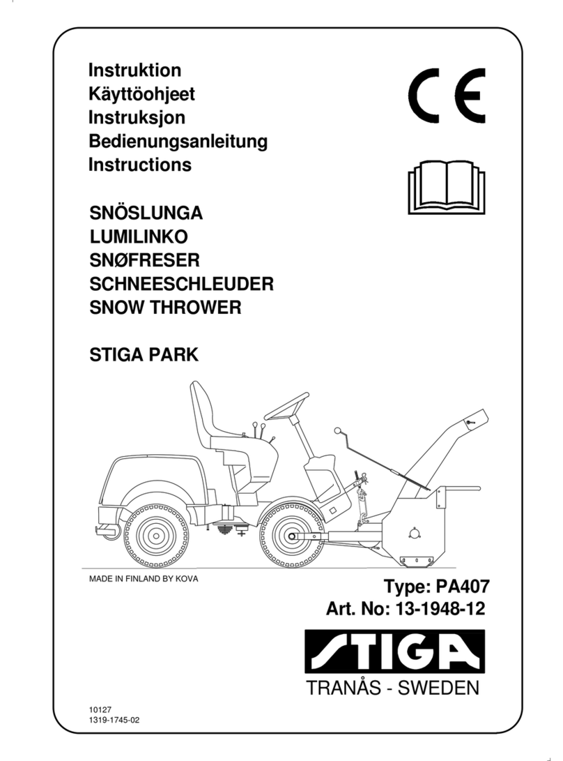
Stiga Park 2/4WD Instruction manual

Edition Manual Chapter Page
2005-05-04 Workshop Manual, Stiga Park 1 General instructions 1
Workshop
manual
Park 2/4WD
2000-2008

Edition Manual Chapter Page
2008-05-19 Workshop Manual, Stiga Park 1 General instructions 1
1 General instructions
Contents in this chapter
General
This Workshop Manual is intended for Stiga Park models 2000-2007. The article numbers
and product names are designated in the tables under “Technical specification” at page 21.
This Manual do not cover repair instructions for the motors. Regarding motors, contact the
respective representative in the actual country.
This Manual and its specifications are valid for machines in their original design. In case of
modified or changed machine, i.e. the motor is replaced, the manual accordance is limited.
The manual is divided in the following chapters:
Chapter 1 is this chapter
Chapter 2 Chassis
Chapter 3 Steering
Chapter 4 Hydraulic system
Chapter 5 Belts
Chapter 6 Control Wires
Chapter 7 Electrical system
1.3.2 Extended guarantee ............. 4
1.3.3 Component guarantee,
chassis .................................. 4
1.3.4 Exeptions .............................. 4
1.3.5 Conditions for validity of
the warranties ........................ 4
1.4 Unpacking and assembly ........ 5
1.4.1 Unpacking ............................. 5
1.4.2 Battery .................................. 6
1.4.3 Assembly .............................. 8
1.4.4 Final checks .......................... 12
1.5 Service ...................................... 13
1.6 Technical specifications ......... 21
1.6.1 Machines .............................. 21
1.6.2 Motors ................................... 28
1.6.3 General tightening torque ..... 28
1.7 Instructions for use .................. 29
1.1 Introduction ...............................2
1.1.1 Responsibility declaration ......2
1.1.2 How this manual is used .......2
1.1.3 Abbreviations .........................2
1.2 Safety Precautions ...................2
1.2.1 Symbols and general
warnings .................................3
1.2.2 Warm parts ............................3
1.2.3 Moving parts ..........................3
1.2.4 Lifting and blocking up ...........3
1.2.5 Cleanliness ............................3
1.2.6 Tightening torque ..................3
1.2.7 Sharp edges ..........................3
1.2.8 Replacement parts ................3
1.2.9 Inspection ..............................3
1.3 Guarantee ..................................4
1.3.1 Guarantee period ..................4

Edition Manual Chapter Page
2008-05-19 Workshop Manual, Stiga Park 1 General instructions 2
1.1 Introduction
1.1.1 Responsibility declaration
In spite of the great care we have taken there may be errors in this publication.
The author cannot be made liable for incorrect or missing information.
GGP SE reserves the right to regularly change product specifications without prior notice.
All the information in this book is based on the information available at the time of
production. Illustrations and photographs may be arranged schematically, which implies
that one picture may cover several models and therefore not correspond exactly with all
models.
1.1.2 How this manual is used
To make this manual easy to understand we have divided the machine into its main
systems and components. These parts are now the different chapters in the book.
Each chapter is divided up into sections.
There is a quick-guide on the cover of this book, which refers to the different chapters. In
each chapter there is a detailed table of contents so that you can easily and quickly find
what you are looking for.
For example, if you are looking for information on the Accessory Lifter you will find this in
chapter 3, Chassis and Body. On the first page in chapter 3 there is a detailed table of
contents which refers to the correct section, in this case section 3.1.
Always check that you are reading the right chapter for your particular machine before
starting the repair work.
1.1.3 Abbreviations
The following abbreviations are used in this manual:
HST Hydrostatic Transmission PTO Power Take Off
1.2 Safety Precautions
This manual has been written primarily for trained mechanics working in a well-equipped
workshop. Nevertheless, the manual contains such detailed information that it can also be
of use to owners who wish to carry out simple service and repairs on their machine.
A basic knowledge of repairs, tools and repair instructions is, however, always a
prerequisite for first-rate results.
A qualified mechanic should always be consulted if the owner does not have sufficient
knowledge to carry out repairs.
During the warranty period all service must be carried out by an Authorised Workshop for
the warranty to be valid.
The following basic points should be observed if the machine is to function perfectly:
• Follow the service schedule.
• Be on the alert for sudden vibrations or abnormal noise to avoid major breakdowns.
• Always use Genuine Spare Parts
• Follow the descriptions in this manual carefully. Do not take any short cuts.

Edition Manual Chapter Page
2008-05-19 Workshop Manual, Stiga Park 1 General instructions 3
1.2.1 Symbols and general
warnings
Warning!
This symbol indicates a risk of
personal injury or damage if the
instructions are not followed.
Note!
Thistextindicatesariskofdamageto
the material or risk of unnecessarily
complicated work if the instructions
are not followed.
1.2.2 Warm parts
Please observe that engine and exhaust
system picks up a lot of heat during use.
This applies above all to the silencer of
machines equipped with catalytic
converter.
Toavoidinjuries,allow the machinetocool
before any kind of repairs are made to or
near parts of the engine or exhaust
system.
1.2.3 Moving parts
The machines are all equipped with v-belt
transmissions.Alwaysstoptheengineand
remove the starter key before inspections
or repairs are carried out.
Always use extreme caution when testing
systems with moving parts to avoid
injuries.
Always use Genuine Spare Parts during
service work.
1.2.4 Lifting and blocking up
Before work under the machine, always
make sure that lifting devices and jack-
stands are approved for the weight.
Work safe!
1.2.5 Cleanliness
Clean the machine before starting repairs.
Dirt that penetrates into sensitive
components can seriously influence the
service life of the machine.
1.2.6 Tightening torque
Unless otherwise stated the tightening
torque in the tables in the section
Technical specifications must be used for
thedifferentsizesof screws.This does not
refer to self-tapping screws, which are
mainly used for the assembly of body
parts.
1.2.7 Sharp edges
Watch out for sharp edges, especially
when working with the mower deck. The
blades can be very sharp. Always wear
gloves when working with the blades.
1.2.8 Replacement parts
Always use Genuine Spare Parts during
service work.
1.2.9 Inspection
Each part dismantled in conjunction with
service work must be inspected.
Examine for: wear, cracks, out of
roundness, straightness, dents,
discolouring, abnormal noise and
jamming.

Edition Manual Chapter Page
2008-05-19 Workshop Manual, Stiga Park 1 General instructions 4
1.3 Guarantee
1.3.1 Guarantee period
For consumer use: two years from date of
purchase.
For professional use: 200 hours or three
months, whichever comes first.
1.3.2 Extended guarantee
The guarantee period can be extended to
a maximum of 300 hours or 3 years from
the date of purchase provided that the
prescribed basic services have been
carried out at an authorised Stiga Service
workshop during the relevant guarantee
period.Theservicesmustbeverifiedinthe
service book.
1.3.3 Component guarantee,
chassis
Faults occurring in the machine’s bearing
in the articulated steering joint, as well as
the front and rear chassis, are covered by
a 10 year component guarantee from the
date of purchase
The guarantee is valid provided that the
prescribed basic services have been
carried out at an authorised service
workshop during the relevant guarantee
period.Theservicesmustbeverifiedinthe
service book.
1.3.4 Exeptions
The extended warranty does not cover
damage due to the following:
• Neglect by users to acquaint themselves
with accompanying documentation.
• Carelessness.
• Incorrect and non-permitted use or
assembly.
• The use of non-genuine spare parts.
• The use of accessories not supplied or
approved by the manufacturer.
Neither does the warranty cover:
• Wearing components such as blades,
belts, wheels,battery and cables.
• Normal wear.
• Engine and transmission. These are cov-
ered by the engine manufacturer’s war-
ranties, with separate terms and
conditions.
The purchaser is covered by the national
laws of each country. The rights to which
thepurchaserisentitledwiththesupportof
these laws are not restricted by this
warranty.
1.3.5 Conditions for validity of the
warranties
The fully completed warranty card must be
sent to Stiga´s subsidiary or distributor.
In the event of a claim, the service history
must be confirmed with a copy of the
service book.

Edition Manual Chapter Page
2008-05-19 Workshop Manual, Stiga Park 1 General instructions 5
1.4 Unpacking and assembly
Every Stiga Park has undergone an extensive
control programme before delivery. The
machines are delivered as completely
assembled as possible.
Thanksto this theassembly ondelivery is rapid
and easy.
The correct and careful assembly of the
machineondeliveryisasimplewayofensuring
satisfied customers!
Note!
The machine shall remain placed on the
pallet during the unpacking and
assembly.
1.4.1 Unpacking
Open up the crate and release the part as
follows:
1. Check the air pressure in the tyres. The
pressure is designated on the floor mat.
The air pressure in the tyres is of critical
importance for the performance and
handling of the machine. The correct air
pressure for mowing is 0.6 bar (9 psi) in the
front tyres, and 0.4 bar (6 psi) in the rear
tyres.
When using heavy accessories, e.g. snow
thrower, it may be necessary to increase the
pressure somewhat. However, the
maximum permitted pressure is always
0.8 bar (12 psi).
Too high pressure in the tyres leads to that
the machine drives poor due to:
• A small surface in contact to the ground.
• Hard tyre = less flexibility = self cleaning char-
acteristic deteriorate.
2. Remove the following parts from the
package and put them on the floor.
• The battery (some models).
• The steering wheel.
• The plastic bag, containing owners manuals,
information video and assembly screws.
Too high pressure Correct pressure

Edition Manual Chapter Page
2008-05-19 Workshop Manual, Stiga Park 1 General instructions 6
1.4.2 Battery
The battery can be of the following two types,
depending on tha actual machine:
• Valve regulated type (A)
• Dry charged type (B)
Depending on the battery type, load and
assemble the battery, following the actual
instruction below.
Valve regulated battery
This battery needs limited maintenance. Is has
no electrolyte levels or plugs.
Warning!
Do not wear rings, metallic bracelet,
chainround the neck or similar metal
objects when working with the
battery. It can cause short-circuit,
burns and fire.
Warning!
The battery must be fully charged be-
fore being used for the first time. The
battery must always be stored fully
charged. If the battery is stored while
discharged, serious damage will oc-
cur.
Charging with the engine
The battery can be charged using the engine’s
generator as follows:
1. Install the battery in the machine as shown
below.
2. Place the machine outdoors or install an
extraction device for the exhaust fumes.
3. Start the engine according to the
instructions in the user guide.
4. Allow the engine to run continuously for 45
minutes.
5. Stop the engine. The battery will now be
fully charged.
A
A
B
Charging using battery charger
When charging using a battery charger, a
battery charger with constant voltage
must be used.
Ordering number: 1136-0602-01.
Thebatterycan be damagedifastandard
type battery charger is used.

Edition Manual Chapter Page
2008-05-19 Workshop Manual, Stiga Park 1 General instructions 7
Dry charged battery
Dry charged batteries are delivered without
battery acid in their cells.
Warning!
Filling with battery acid shall take
place in a well illuminated and
ventilated place with rapidly access
to fluiding water for rinsing.
Warning!
Wearrubber gloves and eye protection
and handle the acid with great care to
avoid spillage.
Warning!
The acid can burn the skin and destroy
clothing and other materials it comes
in contact with.
Warning!
Do not wear rings, metallic bracelet,
chainround the neck or similar metal
objects when working with the
battery. It can cause short-circuit,
burns and fire.
Maintain the dry charged battery as follows:
1. Fill carefully all cells with battery acid. The
acid level shall be ca 5 mm above the cell
packet edges.
2. Let the battery acid draw in into the cell
material during 20 minutes. Adjust after that
the cell levels again.
3. Let the battery stand for 2 hours before use.
During this time it is suitably to assemble the
rest of the machine as described below.
4. After 2 hours, install the battery as described
below.
Installation of battery
See also the respective installation manual,
delivered with the machine.
After the battery is charged, remove the motor
casing and install it in the machine. Connect
first the red cable to plus (+) and then the black
cable to minus (-).
If the cables are disconnected/
connected in the wrong order,
there is a risk of a short-circuit
and damage to the battery.
If the cables are interchanged,
the generator and the battery
will be damaged.
Theenginemustneverbedriven
with the battery disconnected.
There is a risk of serious dam-
age to the generator and the
electrical system.

Edition Manual Chapter Page
2008-05-19 Workshop Manual, Stiga Park 1 General instructions 8
1.4.3 Assembly
The assembly procedure shall take place in a
clean, well illuminated and dry place.
Assemble the machine as follows:
Assembly of steering wheel
Instructions for machines with mechanic
steering:
The machine is delivered with two shims, one
with a thickness of 0.5 mm and one with a
thickness of 1.0 mm.
In order to minimise the axial play in the
steering column, the shim washers (0.5 mm)
and/or (1.0 mm) must be installed on the
steering column between the steering column
jacket and the bracket as follows.
1. Install the steering column jacket on the
steering column and secure by knocking in
the tension pin approximately 1/3 of its
length.
2. Pull the steering column jacket and the
steering column up.
3. From the outside, check whether no
washers, the 0.5 mm washer, the 1.0 mm
washer or both washers can be inserted into
the gap. The washer/washers must not be
forced in, as there must be a little axial play.
4. Pull out the cotter pin and dismantle the
steering wheel jacket.
5. Install the washer/washers in accordance
with point 3 above.
6. Install the steering column jacket on the
steering column and secure by knocking in
the tension pin fully. Use a counterhold.
Also make sure that the logo on the steering
wheel is in the correct position.
Instructions for machines with hydraulic
steering:
1. Adjust the machine in the straight
forward direction.
2. Attach the steering wheel with the
logotype readable from the driver
position.

Edition Manual Chapter Page
2008-05-19 Workshop Manual, Stiga Park 1 General instructions 9
Assembly of seat (adjusting knobs under)
Install the mounting in the rear (upper) holes as
follows:
1. Install the shoulder washers (E) on the
screws (F).
2. Insert the screws through the slots in the
bracket. Place a washer (H) between the
seat and the bracket.
3. Tighten the screws in the seat. Tightening
torque: 9±1.7 Nm.
If the screws are tightened more than
9±1.7 Nm, the seat will be damaged.
4. Check that the seat moves easily in the
slots in the bracket.
Installthemounting in the front (lower)holes as
follows:
1. Install a washer (H) on each knob (G).
2. Insert the knobs through the slots in the
bracket and tighten by hand in the seat.
3. Fold the seat down and place it in the
desired position.
4. Tighten the screw knobs (G) by hand.
The screw knobs (G) and the seat will
be damaged if tools are used.
Assembly of seat (adjusting wings under)
Release the catch (S) and fold up the seat
bracket.
Install the mounting in the rear (upper) holes as
follows:
1. Install the shoulder washers (F) on the screws
(K).
2. Insert the screws through the slots in the
bracket. Place a washer (I) between the seat
and the bracket.
3. Tighten the screws in the seat. Tightening
torque: 9±1.7 Nm.
H
E
F
HG
FK
IHG
S
I

Edition Manual Chapter Page
2008-05-19 Workshop Manual, Stiga Park 1 General instructions 10
If the screws are tightened more than
9±1.7 Nm, the seat will be damaged.
4. Check that the seat moves easily in the slots
in the bracket.
Installthemounting in the front (lower)holes as
follows:
1. Install the screw knobs (H) on the screws (G).
2. Install a washer (I) on each screw.
3. Insert the screws through the slots in the
bracket and tighten by hand in the seat.
4. Fold the seat down and place it in the desired
position.
5. Tighten the screw knobs (H) by hand.
The screw knobs (H) and the seat will
be damaged if tools are used.
Assembly of seat (adjusting by lever)
1. Remove the following components from the
seat bracket:
• 4 Nuts (for transport locking, not used).
•4Screws.
• 4 Shoulder washers.
2. Positiontheseatover themountinginthe seat
bracket.
3. Install the shoulder washers on the screws.
4. Insert the screws with the attached shoulder
washers through the slots in the seat bracket
and the holes in the seat plate. Screw the seat
into place.
Tightening torque: 9±1.7 Nm.
If the screws are tightened more than
9±1.7 Nm, the seat will be damaged.
5. Check that the seat moves easily in the slots
in the bracket.

Edition Manual Chapter Page
2008-05-19 Workshop Manual, Stiga Park 1 General instructions 11
Arm rest (if applicable)
The arm rests and the installation components
are supplied in a separate box. Assemble as
follows:
1. Assemble the left and right mounts onto the
seat. Use 3 screws (Q) supplied at each
side.
2. Assemble the arm rests with screws (R),
nuts (S) and spacers (T).
3. Tighten the screws so that the arm rests
simply can be folded up/down.
Towing plate
Fitting according to customer requirements.
Engine oil
Check the oil level in the engine and top up if
necessary.
HST oil
Check the oil level in the HST’s expansion tank
after test driving, and top up if necessary.
Q
R
T
S

Edition Manual Chapter Page
2008-05-19 Workshop Manual, Stiga Park 1 General instructions 12
1.4.4 Final checks
Removing from pallet
All the above measures shall have been done
with the machine standing on the pallet. Now,
loosen the remaining straps and roll off the
machine from the pallet.
Fit and adjust accessories.
Test driving
Warning!
Do not drive without a work
equipment (mover deck) attached.
Risk for turning over.
Drive the machine for a few minutes. Test all
the functions. Pay special attention to the
safety functions. If the machine is to be
delivered with mower deck or other
accessories, fit these before test driving the
machine.
HST oil
Check the oil level in the HST’s expansion tank
after test driving, and top up if necessary.
Steering chain / Steering wire
Check that the steering chain / steering
wire is sufficiently taut. Adjust if
necessary.
Miscellaneous
Give the machine a general inspection.
• Is the machine clean?
• Is there any oil leakage?
• Abnormal noise or rattle?
Receipt
By filling in the guarantee certificate you
guarantee that the delivery service has
been correctly conducted.
Remember to make sure that the
customer receives all the documentation
when the machine is collected / delivered.

Edition Manual Chapter Page
2008-05-19 Workshop Manual, Stiga Park 1 General instructions 13
1.5 Service
Every new machine is delivered with a service book. This service book is part of the active
post-market programme and shall be kept in a safe place during the entire lifetime of the
machine. Hand over the service book if the machine is sold in 2:nd hand.
Service should generally be carried out at least every 50 operating hours (exception of the
f
irst service), although in accordance with the conditions below.
T
here are three different grades of service events. Every service event consists of a
number of service points as described in the following paragraphs. Every service point has
a
number which refer to a describing text after the schedules.
Some service points do not coincide with the scheduled service intervals, but shall be
performed in connection with a scheduled service when possible. E.g. some items shall be
performed at every second service and some also between two services. These service
points are described with procedure and interval in the respective “Instruction for use”.
T
ypical service points wich not coincide with scheduled service intervals are:
• Cleaning/changing air filter in some motors.
• Change of oil in some motors.
• Valve adjustments for some motors.
• Change of transmission oil in 4 WD machines.
• Change of spark plug in some motors.

Edition Manual Chapter Page
2008-05-19 Workshop Manual, Stiga Park 1 General instructions 14
1
.
5
.
1
Fi
rs
t
S
erv
i
ce
The first service shall be performed within 5
hours of running and includes the service
points as per the table below.
This service is very important to safeguard
the continuing function of the machine.
*) See section 4.
Number Service point
1Safety check.
2Tyres, air pressure.
3Engine oil, change.
Machines with filter, replace it
together with the oil.
4A Oil level in HST, check
(Valid for machines with HST
only).
5Belt transmissions, check.
6Steering adjustment.
7Battery check.
21 Test driving.
*Transmission oil, change and
tank filter/HST filter, clean.
(Valid for 4WD machines only)
*Filter for transmission oli,
change. (Valid for 4WD
machines with external
hydraulic only)
1
.
5
.
2
I
n
t
erme
di
a
t
e
S
erv
i
ce
The intermediate service shall be conducted
between two basic services. That means:
For Pro Diesel: 100 hours after a basic
service.
Forallothermachines:50hoursafterabasic
service.
The intermediate service is not as extensive
as the Basic Service and can therefore be
conducted by the customer, or by an
authorisedServiceWorkshop.Regardlessof
who conducts the service, it must be
documented in the service book.
Number Service point
1Safety check.
2Tyres, air pressure.
3Engine oil, change.
4A Oil level in HST, check.
(Valid for machines with HST
only).
6Steering adjustment.
9Air filter, cleaning.

10 Air filter catalytic converter,
cleaning.
11 Cooling fins, clean.
12 Lubrication

Edition Manual Chapter Page
2008-05-19 Workshop Manual, Stiga Park 1 General instructions 15
1.5.3 Basic Service
The basic service shall be conducted as follows:
For Pro Diesel: Every 200 hours or every
year, which first occur.
For all other machines:Every 100 hours or every
year, which first occur.
The Basic Service must always be conducted by
an authorized Service Workshop, and
documented with a stamp in the service book.
*) See also “Safety check”.
**) See also the mover deck manual.
***) See the motor manual.
Number Service item
1Safety check
2Tires, air pressure
3Engine oil, change.
Machines with filter, replace it
together with the oil.
4B Oil in HST, check/replace.
Machines with filter, replace it
together with the oil.
(Valid for machines with HST
only)
5Belt transmissions, check
6Steering adjustment
7Battery check
8Air filter for engine, clean/
replace
Number Service item
9Air filter catalytic converter,
clean
(Valid for machines with
catalytic converter only)
10 Cooling fins, clean
11 Spark plug, check/replace
13 Transmission, check
14 Speed check
15 Bearing boxes, check**
16 Exhaust system, check*
17 Electrical system, check*
18 Mower deck, check**
19 Blades, check**
20 Power take-off, check
21 Control check
22 Valve play***
23 Test driving

Edition Manual Chapter Page
2008-05-19 Workshop Manual, Stiga Park 1 General instructions 16
1.5.4 Description of service points
Senator, electrical safety check
Test Status Action Result
1 Brake pedal not pressed.
PTO activated.
No gear activated.
Turn the key and make a
start attempt. Motor shall not
start.
2 Brake pedal pressed.
PTO activated.
No gear activated.
Turn the key and make a
start attempt. Motor shall not
start.
3 Brake pedal not pressed.
PTO not activated.
A gear is activated.
Turn the key and make a
start attempt. Motor shall not
start.
4 Motor running.
PTO activated. Operator rises from the
seat. Motor shall
stop.
5 Motor running.
A gear activated. Operator rises from the
seat. Motor shall
stop.
6 Motor running. Disconnectcablefromthe
shut off valve. Motor shall
stopafterafew
minutes.
President and Comfort, electrical safety check
Test Status Action Result
1 Brake pedal not pressed.
PTO not activated. Turn the key and make a
start attempt. Motor shall not
start.
2 Brake pedal pressed.
PTO activated. Turn the key and make a
start attempt. Motor shall not
start.
3 Motor running.
PTO activated. Operator rises from the
seat. Motor shall
stop.
4 Motor running. Disconnectcablefromthe
shut off valve. Motor shall
stopafterafew
minutes.
1. Safety check
Check the safety functions. It is often appropriate to do this check in conjunction with test
driving. The following items shall be checked at all machines:
• No leakage on fuel lines and connections.
• No mechanical damages to the electrical cables. All insulation intact.
• The muffler shall be undamaged and its screws tightened. No exhaust leakage in con-
nections.
The electrical check items at the respective machine up to model 2004 are listed in the
tables below. For models 2005 and up, see the respective “Instructions for use”.

Edition Manual Chapter Page
2008-05-19 Workshop Manual, Stiga Park 1 General instructions 17
Royal and Pro 16, electrical safety check
Test Status Action Result
1 Brake pedal not pressed.
PTO not activated. Turn the key and make a
start attempt. Motor shall not
start.
2 Brake pedal pressed.
PTO activated. Turn the key and make a
start attempt. Motor shall not
start.
3 Motor running.
PTO activated. Operator rises from the
seat. Motor shall not
start.
4 Cruise control activated. Operator rises from the
seat. Cruise control
shall
disengage
5 Motor running. Disconnectcablefromthe
shut off valve. Motor shall
stopafterafew
minutes.
Pro 20, electrical safety check
Test Status Action Result
1 Brake pedal not pressed.
PTO magnetic clutch not activated. Turn the key and make a
start attempt. Motor shall not
start.
2 Brake pedal pressed.
PTO magnetic clutch activated. Turn the key and make a
start attempt. Motor shall not
start.
3 Motor running.
PTO magnetic clutch activated. Operator rises from the
seat. PTO magnetic
clutch shall
disengage.
4 Cruise control activated. Operator rises from the
seat. Cruise control
shall
disengage.
5 Hydraulic lift in neutral position. Attempt to engage the
PTO magnetic clutch. PTO magnetic
clutch shall not
engage.
6 Motor running. Disconnectcablefromthe
shut off valve. Motor shall
stopafterafew
minutes.

Edition Manual Chapter Page
2008-05-19 Workshop Manual, Stiga Park 1 General instructions 18
Pro Diesel, electrical safety check
Test Status Action Result
1 Brake pedal not pressed.
PTO magnetic clutch not activated. Turn the key and make a
start attempt. Motor shall not
start.
2 Brake pedal pressed.
PTO magnetic clutch activated. Turn the key and make a
start attempt. Motor shall not
start.
3 Motor running.
PTO magnetic clutch activated. Operator rises from the
seat. PTO magnetic
clutch shall
disengage.
4 Cruise control activated. Operator rises from the
seat. Cruise control
shall
disengage
5 Hydraulic lift in neutral position. Attempt to engage the
magnetic clutch. PTO magnetic
clutch shall not
engage.

Edition Manual Chapter Page
2008-05-19 Workshop Manual, Stiga Park 1 General instructions 19
2 Tyres, air pressure
Checktheairpressure.Adjustifnecessary.
The recommended air presure is
designated at the floor mat.
3 Engine oil and oil filter
See the “Instructions for use”, delivered
withthe machine or“Instructions for use” at
page 29.Seealsotheenginemanufacturer
manual.
4 Oil, HST
See the “Instructions for use”, delivered
with the machine.
5 Belt transmissions, check
Check the condition of all the belts and belt
tensioners.
6 Steering, adjustment
See section 3.
7 Battery, check
Valid for dry charged batteries only.
Check the acid level. Top up with distilled
water if necessary. See page 6-7.
8 Engine air filter
See the “Instructions for use”, delivered
with the machine. See also the engine
manufacturer manual.
9 Catalytic converter air filter
See the “Instructions for use”, delivered
with the machine. See also the engine
manufacturer manual.
10 Cooling fins
Remove protective covers from the engine
and cleans between cooling fins. Use a
brush and compressed air. See also the
engine manufacturer manual.
11 Spark plug
Remove the spark plug (not valid for Pro
Diesel)andcleanitorreplaceifnecessary.
See also the engine manufacturer manual.
12 Lubrication
Lubricate the articulation point (4 nipples)
and all moving parts such as wires and
levers. See also the instruction manual,
delivered with the machine.
13 Transmission
Listen for abnormal noise.
Manual models: Check that the drive
functionworks properly atall gears. Adjust
if required.
14 Speed check
Check that the speed corresponds to the
specified value. See pages 18-22.
15 Bearing boxes
Listen for abnormal noise from the
bearings. Check that there are no wear,
play or seizure.
16 Exhaust system
Check that there are no cracks,leakage or
other damages. Check the attachment
devices. See also the engine
manufacturer manual.
17 Electrical system
Check that there are no damaged cables,
contacts or other devices. Check that all
cables are properly secured to the chassis
and with cable holders. Check that there is
no friction between cables and chassis,
which can result in cable damage and
short circuit.
Table of contents
Other Stiga Snow Blower manuals

Stiga
Stiga ST 526 A User manual

Stiga
Stiga ST 526 S User manual

Stiga
Stiga ST 526 S Series User manual

Stiga
Stiga SNOW CUBE User manual

Stiga
Stiga ST 4851 AE User manual

Stiga
Stiga ST 1074 POWER User manual

Stiga
Stiga SNOW-THROWERS ST 1333 PRO User manual

Stiga
Stiga ST 1151 E User manual

Stiga
Stiga PARK 121 M User manual

Stiga
Stiga ST 700 Li 48 Series User manual

Stiga
Stiga Snow Rise User manual

Stiga
Stiga SNOW BLIZZARD User manual

Stiga
Stiga ST 3146 P User manual

Stiga
Stiga DUO LINE User manual

Stiga
Stiga ST 515 Li User manual

Stiga
Stiga ST 866 ROYAL User manual

Stiga
Stiga PRO 1371 User manual

Stiga
Stiga CHASSE-NEIGE 18-2862-26 User manual

Stiga
Stiga ST 929 T PRO Manual

Stiga
Stiga SNOW STORM User manual