Boundary Devices Nitrogen53 User manual

1
Revision 1.3
Nitrogen53 Hardware User Manual
Revision History
Date Revision Description
03-08-2011 1.0 First Draft
04-04-2011 1.1 Updated Pin Outs
05-24-2011 1.2 Updated Board Layout
06-27-2011 1.3 Updated Pin Outs for Touch screen

2
Revision 1.3
1 Contents
1 Contents ....................................................................................................................................... 2
2 Overview...................................................................................................................................... 3
3 Electrical Characteristics ............................................................................................................. 3
4 Connector Details......................................................................................................................... 4
5 Mounting.................................................................................................................................... 11

3
Revision 1.3
2 Overview
The Nitrogen53 is based on the next generation ARM-Cortex A8 processor from Freescale, the
IMX53. With expanded DDR2 memory capacity of up to 1GB at 800MHz and processor speed
of 1GHz, the IMX53 is a powerful multimedia platform capable of 1080P video playback. The
Nitrogen53 was designed to take advantage of the video performance of the IMX53 by offering
multiple display interfaces including HDMI, LVDS, and TTL. With OpenGL® ES 2.0 and
OpenVG™ 1.1 hardware accelerators, the IMX53 is ideal for 3D applications.
The hardware specifications for the Nitrogen53 are the following:
•Freescale IMX53 Processor – 1GHZ
•Power Management IC
•512MB DDR2 400MHz memory (up to 1GB)
•2MB Serial Flash
•TTL/HDMI/LVDS Display Interface
•5V DC input voltage standard (12V versions available)
•2 microSD Card slots
•1 microUSB OTG
•3 USB Host Ports
•4-wire/5-wire Resistive Touch Screen Support
•Microphone In
•Amplified Audio Out/Headphone Jack
•10/100 Ethernet with POE Support
•Power On/Off + Android Buttons (Menu, Home, Back, Search)
•Interface to 5MP Omnivision 5642 Camera Sensor
•I2C/SDIO Interface available
•3 RS232 Ports
•SATA Hard Drive
•Battery Backup for RTC
•Component Video Output
•LED Backlight Driver
•General Purpose I/O for Device Control
•WiFi/Bluetooth/GPS/Accelerometer Available via daughter board
3 Electrical Characteristics
Parameter Min Typ
Max Unit
Main Input Voltage TBD
5 TBD
V
Power Consumption* - 2.5 TBD
W
CPU Clock - 1.0 1.0 GHz
*The Power Consumption refers to a single board with no other peripherals plugged in.

4
Revision 1.3
4 Connector Details
As shown in Figure 1, the Nitrogen53 board contains a wide variety of I/O options. This section
will focus on the details of each connector.
5
Revision 1.3
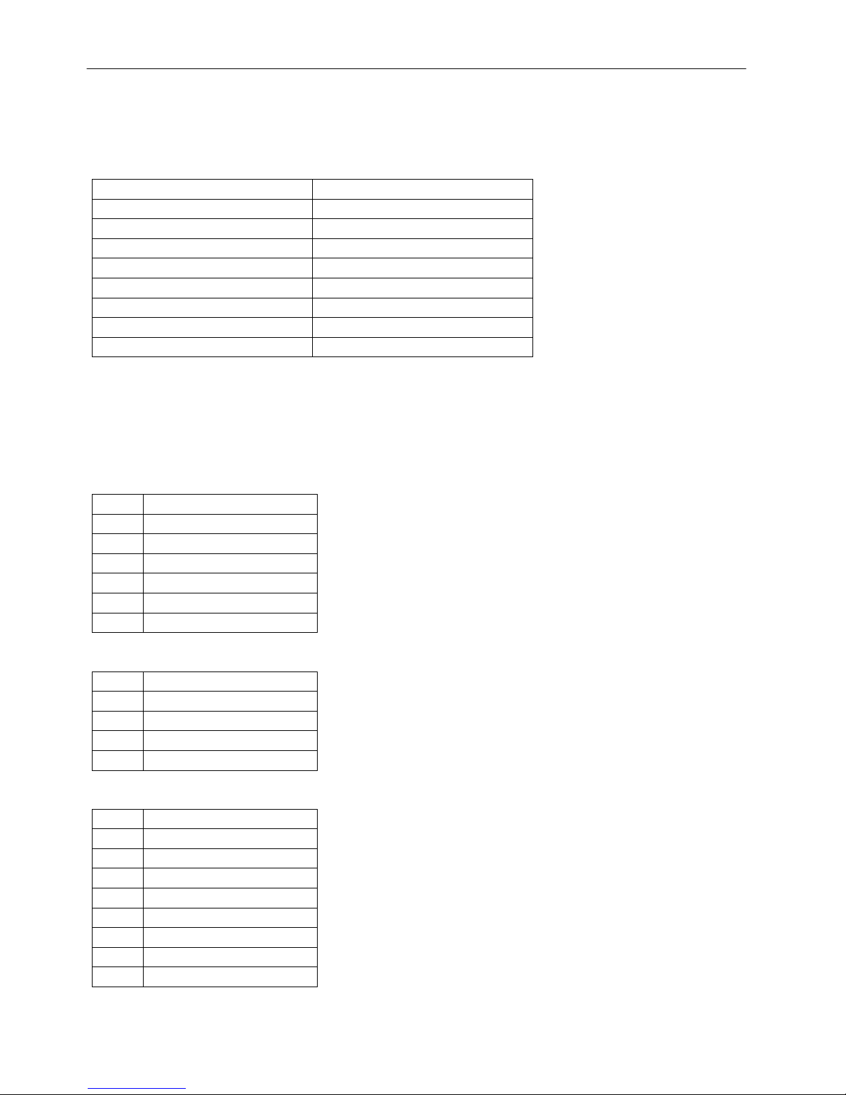
4.1 Standard Connectors
The list of industry standard connectors with known pin outs is the following:
Ref Designator Function
J16 USB OTG
J17 10/100 Ethernet
J14 2 x USB Host
J11/J12 microSD Slot
J26 HDMI (DVI Signals)
J10 DC Power Jack
J20 Headphone Jack
J22 SATA
4.2 Custom Connectors
The Nitrogen53 board has a wide variety of peripheral interfaces available via custom
connectors.
J1: COM1 & COM2 (Molex 53047-0610)
Pin# Function
1 UART1 TX
2 +5V
3 GND
4 UART2 TX
5 UART2 RX
6 UART1 RX
J3: COM3 (Molex 53047-0410)
Pin# Function
1 +5V
2 UART3 TX
3 UART3 RX
4 GND
J5: JTAG (Molex 53047-0810)
Pin# Function
1 RESET1
2 GND
3 TRST*
4 TDO
5 TDI
6 TCLK
7 TMS
8 GND

6
Revision 1.3
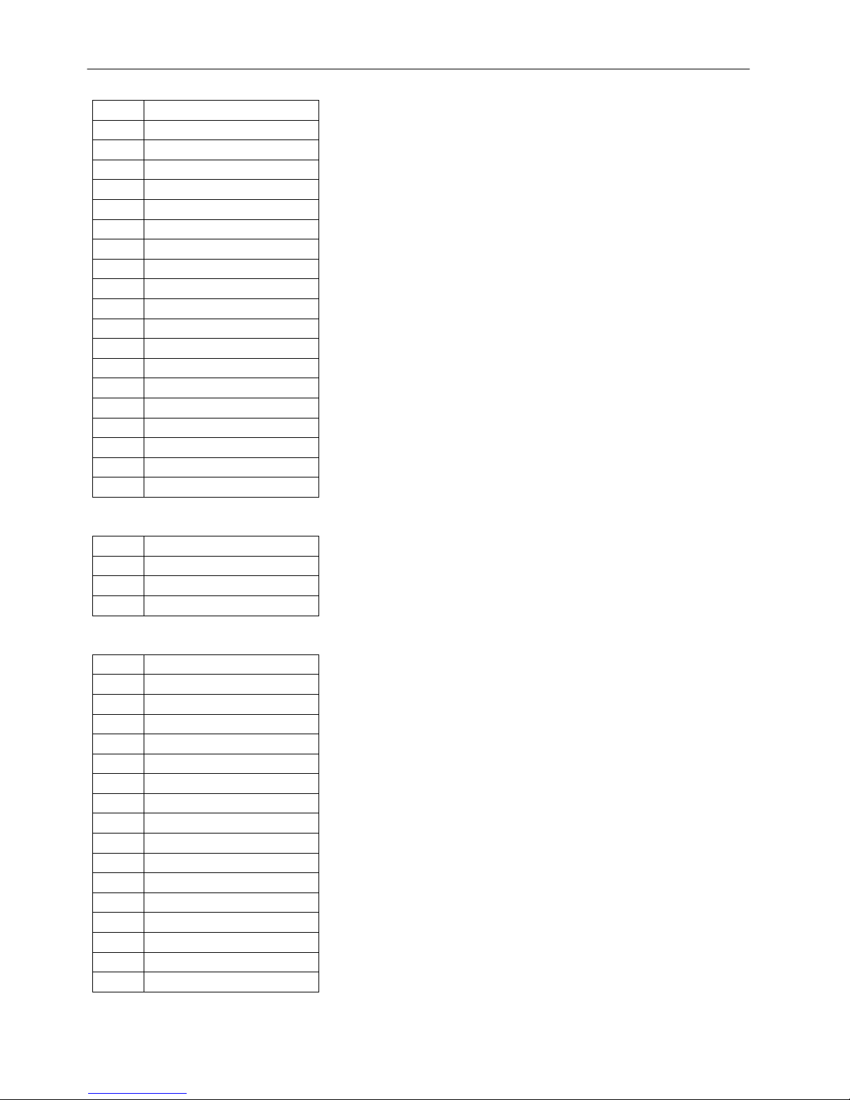
J8: General Purpose Input/Output (Molex 54167-0308)
Pin# Function
1 GND
2 GND
3 EIM_DA0
4 EIM_DA1
5 SD3_CMD
6 SD3_CLK
7 SD3_DATA0
8 SD3_DATA1
9 SD3_DATA2
10 SD3_DATA3
11 GPIO2_24
12 GPIO2_21
13 GPIO2_20
14 GPIO2_19
15 AUD3_TXC
16 AUD3_TXD
17 AUD3_TXFS
18 AUD3_RXD
19 PWM0
20 GPIO5_2
21 GPIO_9
22 GPIO3_23
23 UART3_CTS
24 UART3_RXD
25 UART3_RTS
26 UART3_TXD
27 3.3V
28 3.3V
29 GND
30 GND
J9: I2C (Molex 53047-0510)
Pin# Function
1 +5V
2 SCL
3 SDA
4 GPIO
5 GND
J15: USB3 (Molex 53047-0410)
Pin# Function
1 +5V

7
Revision 1.3
2 USBDN_DM3
3 USBDN_DP3
4 GND
J18: POE Output (Singatron SSW-1-04-01-T-S)
POE Output is meant to interface with BD POE module. If you need further details, please
contact us.
J19: Audio out (Molex 53047-0210)
Pin# Function
1 VO-
2 VO+
J21: Microphone In (Molex 53047-0210)
Pin# Function
1 MIC_IN
2 Common
J23: TTL Display Interface (Omron XF2M-4515-1A)
Pin# Function
1 GND
2 GND
3 3.3V
4 3.3V
5 R0
6 R1
7 R2
8 R3
9 R4
10 R5
11 R6
12 R7
13 G0
14 G1
15 G2
16 G3
17 G4
18 G5
19 G6
20 G7
21 B0
22 B1
23 B2
24 B3
25 B4
8
Revision 1.3
26 B5
27 B6
28 B7
29 GND
30 CLK
31 3.3V
32 HSYNC
33 VSYNC
34 RDY
35 3.3V
36 GND
37 NC
38 NC
39 NC
40 NC
41 GND
42 NC
43 NC
44 GPIO
45 PWM
J24: External Power Connector (Tyco 640457-3)
Pin# Function
1 +5V
2 GND
3 GND
J25: Camera (AVX 6210033340800)
Pin# Function
1 GND
2 D19
3 D18
4 D17
5 D16
6 D15
7 D14
8 D13
9 D12
10 D11
11 D10
12 D9
13 D8
14 SCL
15 SDA
16 GND

9
Revision 1.3
17 CLK
18 GND
19 2.8V
20 1.8V
21 2.8V
22 2.8V
23 GND
24 DATA_EN
25 GND
26 CAM_RESET
27 VSYNC
28 HSYNC
29 GND
30 PIX_CLK
31 GPIO_2
32 GND
33 GPIO_7
J28: Component Video (Molex 53047-0710)
Pin# Function
1 +5V
2 IOB
3 IOG
4 IOR
5 VGA_HSYNC
6 VGA_VSYNC
7 GND
J30: 4-wire Resistive Touch (Molex 52271-0479)
Pin# Function
1 X-
2 Y-
3 X+
4 Y+
J31: LED Backlight (Molex 53047-0510)
Pin# Function
1 LED String 1 Cathode
2 LED String 2 Cathode
3 LED String 3 Cathode
4 LED Anode
5 LED Anode

10
Revision 1.3
J34: 5-wire Resistive Touch (Molex 52207-0585)
Pin# Function
1 X-
2 Y+
3 X+
4 Y-
5 Sense
J35: Android Buttons (Molex 53047-0710)
Pin# Function
1 GPIO ON/OFF
2 MANUAL ON/OFF
3 HOME
4 SEARCH
5 BACK
6 MENU
7 GND
J37: Auxiliary Power (Molex 53047-0410)
Pin# Function
1 Tracks DC INPUT
voltage
2 NC
3 PWM0
4 GND
CON1: LVDS (Hirose DF14-20P-1.25H)
Pin# Function
1 3.3V
2 3.3V
3 GND
4 GND
5 TX0_N
6 TX0_P
7 GND
8 TX1_N
9 TX1_P
10 GND
11 TX2_N
12 TX2_P
13 GND
14 CLK_N
15 CLK_P
16 GND
17 TX3_N

11
Revision 1.3
18 TX3_P
19 GND
20 GND
5 Mounting
The overall dimensions of the Nitrogen53 board are 116x75mm.
Table of contents
Other Boundary Devices Motherboard manuals


