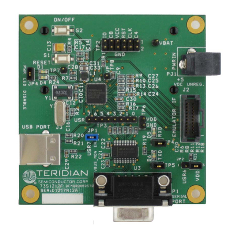
71M6534H Demo Board User’s Manual
Page: 5 of 86 © 2005-2007 TERIDIAN Semiconductor Corporation V2-0
Table of Contents
1GETTING STARTED................................................................................................................................................ 9
1.1 General.................................................................................................................................................................... 9
1.2 Safety and ESD Precautions ................................................................................................................................. 9
1.3 Demo Kit Contents................................................................................................................................................. 9
1.4 Demo Board Versions.......................................................................................................................................... 10
1.5 Compatibility......................................................................................................................................................... 10
1.6 Suggested Equipment not Included ................................................................................................................... 10
1.7 Demo Board Test Setup....................................................................................................................................... 10
1.7.1 Power Supply Setup........................................................................................................................................ 13
1.7.2 Cable for Serial Connection (Debug Board) .................................................................................................... 13
1.7.3 Checking Operation......................................................................................................................................... 14
1.7.4 Serial Connection Setup.................................................................................................................................. 15
1.8 Using the Demo Board......................................................................................................................................... 16
1.8.1 Serial Command Language............................................................................................................................. 17
1.8.2 Using the Demo Board for Energy Measurements.......................................................................................... 25
1.8.3 Adjusting the Kh Factor for the Demo Board................................................................................................... 25
1.8.4 Adjusting the Demo Boards to Different Current Transformers ....................................................................... 26
1.8.5 Adjusting the Demo Boards to Different Voltage Dividers ............................................................................... 26
1.9 Calibration Parameters........................................................................................................................................ 27
1.9.1 General Calibration Procedure........................................................................................................................ 27
1.9.2 Calibration Macro File ..................................................................................................................................... 28
1.9.3 Updating the 6534_demo.hex file.................................................................................................................... 28
1.9.4 Updating Calibration Data in Flash Memory without Using the ICE or a Programmer .................................... 28
1.9.5 Automatic Calibration (Auto-Cal)..................................................................................................................... 29
1.9.6 Loading the 6534_demo.hex file into the Demo Board.................................................................................... 29
1.9.7 The Programming Interface of the 71M6534/6534H ....................................................................................... 31
1.10 Demo Code........................................................................................................................................................ 32
1.10.1 Demo Code Description............................................................................................................................... 32
1.10.2 Important Demo Code MPU Parameters ..................................................................................................... 33
1.10.3 Useful CLI Commands Involving the MPU and CE...................................................................................... 39
1.11 Using the ICE (In-Circuit Emulator)................................................................................................................. 39
2APPLICATION INFORMATION............................................................................................................................. 41
2.1 Calibration Theory................................................................................................................................................ 41
2.1.1 Calibration with Three Measurements............................................................................................................. 41
2.1.2 Calibration with Five Measurements ............................................................................................................... 43
2.1.3 Fast Calibration ............................................................................................................................................... 44
2.2 Calibration Procedures........................................................................................................................................ 45
2.2.1 Calibration Procedure with Three Measurements ........................................................................................... 46
2.2.2 Calibration Procedure with Five Measurements.............................................................................................. 47
2.2.3 Fast Calibration – Auto-Calibration.................................................................................................................. 47
2.2.4 Calibration Procedure for Rogowski Coil Sensors........................................................................................... 48
2.2.5 Calibration Spreadsheets ................................................................................................................................ 49
2.2.6 Compensating for Non-Linearities................................................................................................................... 52
2.3 Calibrating and Compensating the RTC............................................................................................................. 53
2.4 Schematic Information......................................................................................................................................... 54
2.4.1 Components for the V1 Pin ............................................................................................................................. 54
2.4.2 Reset Circuit.................................................................................................................................................... 54
2.4.3 Oscillator ......................................................................................................................................................... 55


