Maxtang EHL-10 User manual

EHL-10 Mini-ITX Motherboard

Copyright
© 2021 Shenzhen Maxtang Computer Co., Ltd. All rights reserved. No part of this publication may be reproduced,
copied, stored in a retrieval system, translated into any language, or transmitted in any form or by any means,
electronic, mechanical, photocopying, or otherwise, without the prior written consent of Shenzhen Maxtang
Computer Co., Ltd (hereinafter referred to as “Maxtang”).
Disclaimer
Maxtang reserves the right to make changes and improvements to the products described in this document without
prior notice. Every effort has been made to ensure the information in the document is correct; however, Maxtang
does not guarantee this document is error-free.
Maxtang assumes no liability for incidental or consequential damages arising from misapplication or inability to use
the product or the information contained herein, nor for any infringements of rights of third parties, which may result
from its use.
Trademarks
All the trademarks, registrations, and brands mentioned herein are used for identification purposes only and may be
trademarks and/or registered trademarks of their respective owners.

Shenzhen Maxtang Computer Co., Ltd
1
EHL-10 Motherboard
User Manual
(Version 0.5)
Version:
NO.
Description
Issue Date:
V0.5
Initial Version
2021/08/13

Shenzhen Maxtang Computer Co., Ltd
2
Contents
EHL10 Motherboard ........................................................................... 1
User Manual ....................................................................................... 1
(Version 0.5)........................................................................................1
Chapter 1 Product Introduction ......................................................................................................3
1.1 Brief Introduction............................................................................................................3
1.2 Parameters ......................................................................................................................3
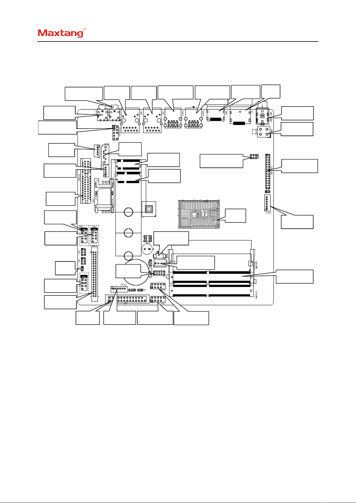
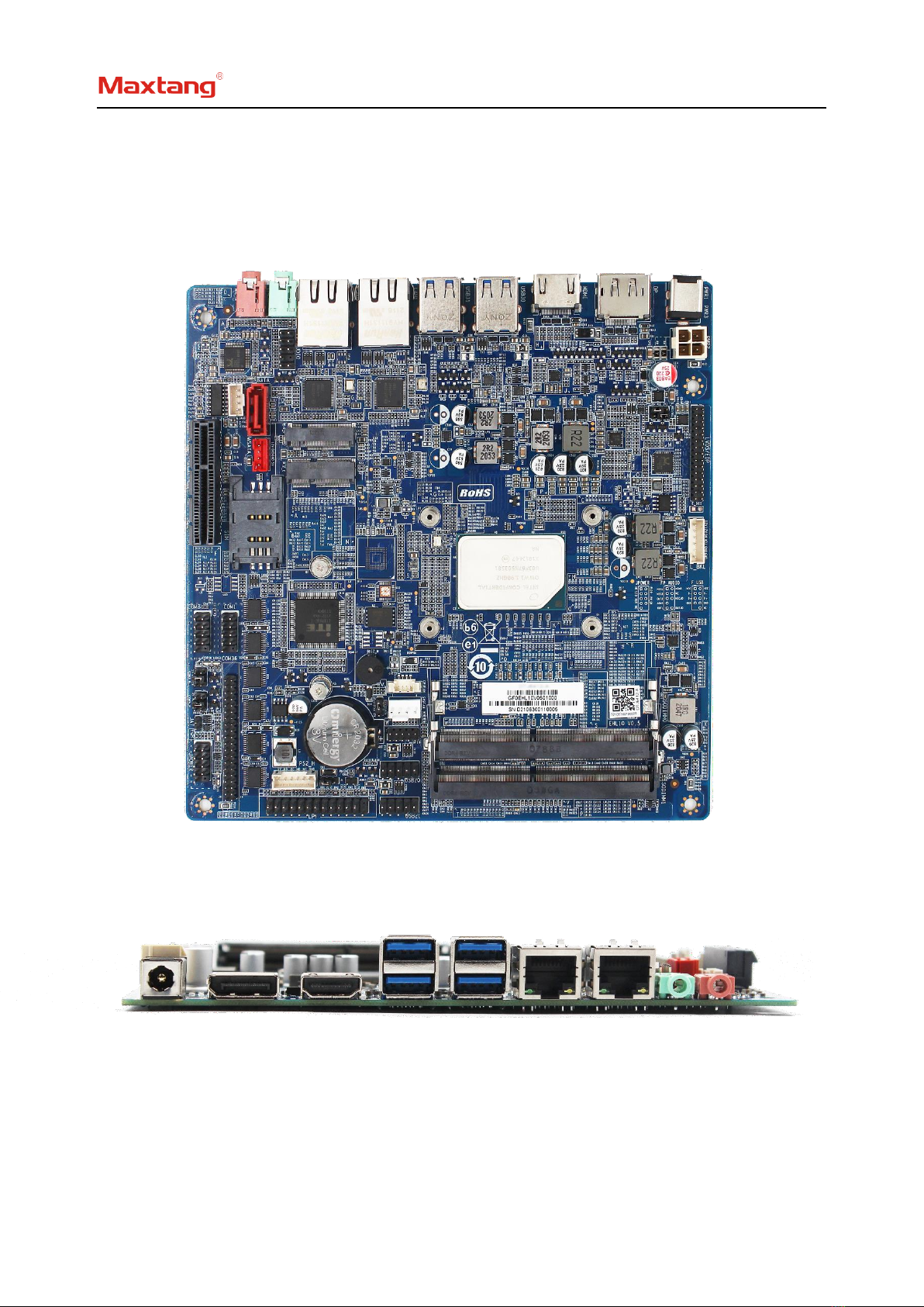
1.3 Connector Diagram .........................................................................................................4
Chapter 2 Hardware............................................................................6
2.1 Jumper Setting ................................................................................................................6
2.2 Memory Slots..................................................................................................................6
2.3 Display Interfaces............................................................................................................6
2.4 Storage...................................................................................................................................8
2.5 Expansion Slot........................................................................................................................8
2.6 USB Interface .........................................................................................................................8
2.7 LAN.........................................................................................................................................8
2.8 COM .......................................................................................................................................8
2.9 LPT........................................................................................................................................10
2.10 GPIO (Screen Printing: GPIO) .............................................................................................10
2.11 Board Power Supply...........................................................................................................10
2.12 Switch Panel Pin.................................................................................................................11
2.13 PS/2 Socket ............................................................................... 11
2.14 Hardware Auto Start (Screen Printing: JAT).......................................................................11
2.15 CPU FAN Socket...........................................................................................................12
2.16 System Fan ..................................................................................................................12
2.15 CMOS Clearance/Retention...............................................................................................12

Shenzhen Maxtang Computer Co., Ltd
3
Chapter 1 Product Introduction
1.1 Brief Introduction
The EHL-10 is a mini ITX motherboard based on the Intel Elkhart Lake platform; features a small form
factor, low power consumption, and high performance.
1.2 Parameters
CPU:
Intel Atom x6425RE——4Cores 4Threads, Base Frequency 1.9GHz, TDP 12W
Intel Atom x6427FE——4Cores 4Threads, Base Frequency 1.9GHz, TDP 12W
Intel Celeron J6412——4Cores 4Threads, Base Frequency 2.00GHz, Burst Frequency 2.60 GHz, TDP 10W
Intel Pentium J6426——4Cores 4Threads, Base Frequency 2.00GHz, Burst Frequency 3.00 GHz, TDP 10W
Memory: 2x SO-DIMM DDR4-3200, supports dual-channel, maximum capacity: 32GB
GPU: Integrated Graphics based on CPU, display via 1x HDMI2.0, 1xDP,1x LVDs (eDP optional)
Storage: 1 x M.2 Key B slot for 2242/2280 SATA SSD, 1 x SATA3.0 standard interface
USB: 4x USB3.2 Gen 1, 4x USB2.0 (onboard pin)
Ethernet: 2x Gigabyte Network Controllers onboard (Intel i211)
Audio: High-Definition Audio Codec, support Line_out, Mic_in, and power amplifier.
Serial I/O: 6x RS232 COM (COM2 can be set as RS485 through change the hardware.)
Other I/O: 1x M.2_Key E for 2230 Wi-Fi Card, LPT, GPIO,1*PCIe4X (PCIe2X Signal), SIM slot, optional TPM
Dimension: 170mm x 170mm
Power: 12V DC-in/4Pin Power
Operating Temperature: -20℃~60℃

Shenzhen Maxtang Computer Co., Ltd
4
DC_IN
PWR2
SYS_FAN
DP
HDMI
2*USB3.2
2*USB3.2
LAN1
LAN2
3
LINE_OUT
MIC_IN
FP-AUDIO
JAUD
SATA
PCIEX4
PWSATA
M.2_S
M.2_E
COM2
COM1
JAT
JPOWER
COM36
LPT
PS2_H
2*USB2.0
2*USB2.0
GPIO
LVDS/EDP
L_BKL
CPU
SO-DIMM
CPU_FAN
L_VCC/BKL
1.3 Connector Diagram

Shenzhen Maxtang Computer Co., Ltd
5

Shenzhen Maxtang Computer Co., Ltd
6
Chapter 2 Hardware
2.1 Jumper Setting
Please configure the jumpers according to your requirements before installing the hardware.
How to identify the first header of jumpers and pins: Observe the mark beside the jumper or pins and
find the header marked by “1” or bold line or triangular symbol. Or observe the rear panel and the header
with a square solder pad is the first header.
2.2 Memory Slots
The board provides 2 x SO-DIMM DDR4-3200, supports dual-channel, maximum capacity: 32GB.
Attention: Make sure to hold the memory module and align the key to the module with that on the
memory slot. While choosing a memory module, please make sure the module matches the board’s
specifications.
2.3 Display Interfaces
The board features Integrated Intel UHD graphics through 1xHDMI2.0 standard interface, 1xDP1.4,
1xLVDS(optional eDP) for trio 4K displays.
2.3.1 LVDS
The board supports a dual-channel 24bit LVDS interface, the "L_VCC/BKL" pin is the display working
voltage adjustment jumper, and the " L_BKL" pin is the backlight adjustment jumper.
LVDS Data Pin (Screen printing: LVDS/EDP)
Signal
Pin
Signal
VCC
1
2
VCC
VCC
3
4
GND
GND
5
6
GND
A_DATA0_DN
7
8
A_DATA0_DP
A_DATA1_DN
9
10
A_DATA1_DP
A_DATA2_DN
11
12
A_DATA2_DP
GND
13
14
GND
A_CLK_DN
15
16
A_CLK_DP
A_DATA3_DN
17
18
A_DATA3_DP
B_DATA0_DN
19
20
B_DATA0_DP
B_DATA1_DN
21
22
B_DATA1_DP
B_DATA2_DN
23
24
B_DATA2_DP
GND
25
26
GND
B_CLK_DN
27
28
B_CLK_DP
B_DATA3_DN
29
30
B_DATA3_DP
LVDS Backlight Adjustment Pin (Screen printing: L-BKL)
Pin
Signal
1
GND

Shenzhen Maxtang Computer Co., Ltd
7
2
GND
3
LCD_BKL_ADJ
4
LCD_BKL_ON
5
12V
6
12V
LVDS working Voltage and two-way adjustment jumper (Screen Printing: L_VCC/BKL)
Pin
Setting
Function
1-3
Close
VCC 3.3V
3-5
Close
VCC 5V
2-4
55-6
Close
REV (Backlight Control Reverse)
4-6
Close
STD (Backlight Control Standard)
2.3.2 eDP (Optional)
Optional function, the board supports 2LANE eDP1.3 interface. When it is set as eDP functions, the pin
transmits the eDP signal and disables the LVDS function. The screen power supply controls by the “L_VCC_BKL”
jumper, the “L_BKL” jumper is for screen backlight adjustment.
eDP Data Pin (Screen Printing: LVDS/EDP)
Signal
Pin
Signal
VCC
1
2
VCC
VCC
3
4
EDP_HPD
GND
5
6
GND
EDP_AUXN
7
8
EDP_AUXP
NC
9
10
NC
EDP_DATA0_P
11
12
EDP_DATA0_N
GND
13
14
GND
NC
15
16
NC
EDP_DATA1_P
17
18
EDP_DATA1_N
NC
19
20
NC
NC
21
22
NC
NC
23
24
NC
GND
25
26
GND
NC
27
28
NC
NC
29
30
NC
eDP Backlight Adjustment Pin (Screen Printing: L-BKL)
Pin
Signal
1
GND
2
GND
3
LCD_BKL_ADJ

Shenzhen Maxtang Computer Co., Ltd
8
4
LCD_BKL_ON
5
12V
6
12V
EDP working voltage and two-way adjustment jumper (Screen printing: L_VCC/BKL)
Interface
Setting
Functions
1-3
Close
VCC 3.3V
3-5
Close
VCC 5V
2-4
Close
REV (Backlight control reverse)
4-6
Close
STD (Backlight control standard)
2.4 Storage
The board features 1x SATA3.0 standard interface, transmission rate at 6GB/s, a disk power supply socket;
1 x M.2 Key B slot for 2242/2280 SATA SSD, this M.2 slot also supports a 4G module with standard SIM
extension.
2.5 Expansion Slot
1xM.2 Key_E slot for 2230 Wi-Fi & Bluetooth onboard, 1x PCIE4X (PCIE2X Signal)
2.6 USB Interface
The board supports 4x USB3.2 Gen2 and 4x USB2.0(2.54mm spacing).
USB pin definition (Screen Printing: USB20, USB21)
Signal
Pin
Signal
VCC 5V
1
2
VCC 5V
USB DATA-
3
4
USB DATA-
USB DATA+
5
6
USB DATA+
GND
7
8
GND
NC
9
10
(NC)
2.7 LAN
The board features 2xRJ45 interfaces with high-speed Intel i211 Gigabit network controllers, supports
Magic packet wake-up, and the LAN1 supports PXE network boot.
LED Status Indicators:
LI_LED Status (Green)
Function
ACT_LED Status (Orange)
Function
Always on
Network Connected
Blinking
Data transfer
2.8 COM
The board provides six RS232 onboard serial port headers (onboard COM1, COM2 pin spacing is
2.54mm), COM2 can be changed to RS485 through hardware change.
COM1, COM2 pin definition (Screen Printing: COM1, COM2)

Shenzhen Maxtang Computer Co., Ltd
9
Signal
Pin
Signal
DCD#
1
2
RXD
TXD
3
4
DTR#
GND
5
6
DSR#
RTS#
7
8
CTS#
RI#
9
10
(NC)
COM36 pin definition (Screen: COM36)
Signal
Pin
Signal
DCD#
1
2
RXD
TXD
3
4
DTR#
GND
5
6
DSR#
RTS#
7
8
CTS#
RI#
9
10
(NC)
DCD#
11
12
RXD
TXD
13
14
DTR#
GND
15
16
DSR#
RTS#
17
18
CTS#
RI#
19
20
(NC)
DCD#
21
22
RXD
TXD
23
24
DTR#
GND
25
26
DSR#
RTS#
27
28
CTS#
RI#
29
30
(NC)
DCD#
31
32
RXD
TXD
33
34
DTR#
GND
35
36
DSR#
RTS#
37
38
CTS#
RI#
39
40
(NC)
COM3_P, COM5_P (Screen Printing: COM3_P, COM5_P)
Interface
Setting
Function
1-2
Close
5V
3-4
Close
RI
5-6
Close
12V
COM2 RS485 pin definition:
Signal
RS232
RS485
1
DCD#
DATA-
2
RXD
DATA+
3
TXD
(NC)
4
DTR#
(NC)

Shenzhen Maxtang Computer Co., Ltd
10
5
GND
GND
6
DSR#
(NC)
7
RTS#
(NC)
8
CTS#
(NC)
9
RI#
(NC)
2.9 LPT
A set of 2x13 Pin LPT interfaces onboard. Use an adapter to convert the LPT interface to a standard
parallel port for use. Users can connect it to a printer or other devices according to their needs.
LPT pin definition (Screen Printing: LPT)
Signal
Pin
Signal
STB
1
2
AFD
LPT_ PPD0
3
4
ERROR
LPT_ PPD1
5
6
INIT
LPT_ PPD2
7
8
SLIN
LPT_ PPD3
9
10
GND
LPT_ PPD4
11
12
GND
LPT_ PPD5
13
14
GND
LPT_ PPD6
15
16
GND
LPT_ PPD7
17
18
GND
ACK
19
20
GND
BUSY
21
22
GND
PE
23
24
GND
SLCT
25
26
(NC)
2.10 GPIO (Screen Printing: GPIO)
The board provides a set of 2x5Pin GPIO (2.0mm spacing) 8 programmable I/O lanes in total.
GPIO (Screen Printing: GPIO)
Signal
Pin
Signal
PCH_GPP_G11
1
2
3.3V
PCH_GPP_G12
3
4
PCH_GPP_E15
PCH_GPP_G13
5
6
PCH_GPP_E16
PCH_GPP_G14
7
8
PCH_GPP_E20
GND
9
10
PCH_GPP_E21
2.11 Board Power Supply
The board supports a 12V DC-IN or ATX 12V supplementary power (2x2pin).
PWR1: 12V DC-in

Shenzhen Maxtang Computer Co., Ltd
11
PWR3: ATX12V supplementary power supply socket (2x2PIN)
2.12 Switch Panel Pin
The front control panel interfaces are to connect the functional buttons and indicators on the front
panel.
JPOWER (Screen Printing: JPOWER)
Signal
Pin
Signal
HDD_LED+
1
2
PWR_LED+
HDD_LED-
3
4
PWR_LED-
RSTBTN-
5
6
PWR_ON+
RSTBTN+
7
8
PWR_ON-
NC
9
10
(NC)
2.13 PS/2 Socket
The board provides one 6-pin PS/2 socket.
P2/2 (screen printing: PS2_H)
Pin
Signal
1
+5V
2
KB_DATA
3
KB_CLK
4
MS_ DATA
5
MS_CLK
6
GND
2.14 Hardware Auto Start (Screen Printing: JAT)
JAT (Screen Printing: JAT)
Setting
JAT
Close
Hardware Auto Start
Please note that this jumper’s function is similar to the BIOS’s “Restore AC Power Loss” function. When

Shenzhen Maxtang Computer Co., Ltd
12
the latter is set to “Power On”, the device will start automatically after being connected to power.
2.15 CPU FAN Socket
The board provides a CPU Fan socket for cooling. 5V default power supply.
CPU_FAN (Screen Printing: CPU_FAN)
Pin
Signal
1
VCC
2
GND
3
TAC
4
CTL
2.16 System Fan
The board provides one system fan socket, default 5V for power supply (optional 12V through JSYSFAN).
SYS_FAN (Screen Printing: SYS_FAN)
Pin
Signal
1
GND
2
VCC
3
TAC
4
CTL
JSYSFAN (Screen Printing: JSYSFAN)
Interface
Setting
Function
1-2
Close
5V
2-3
Close
12V
2.15 CMOS Clearance/Retention
CMOS is powered by onboard button batteries. Clearing CMOS will permanently remove the previous
system settings and restore the board system to original settings (factory settings).
Step 1: Turn off the PC and disconnect the power adapter.
Step 2: Use the jumper cap to connect the 1st and 2nd header of JCMOS for 10 seconds, then
disconnect.
Step 3: Restart the device, press the <DEL> button to enter the BIOS, load the optimal default value,
save, and exit the settings.
JCMOS (Screen Printing: JCMOS)
Setting
JCMOS
Close
Clear CMOS
Please do not clear COMS when the PC is connected to power in case board damages.
Other manuals for EHL-10
1
Table of contents
Other Maxtang Motherboard manuals

Maxtang
Maxtang WL10 User manual

Maxtang
Maxtang WL35 User manual

Maxtang
Maxtang DTJ6412-A User manual

Maxtang
Maxtang WL35 User manual

Maxtang
Maxtang KL35 User manual

Maxtang
Maxtang MITX-KL10 User manual

Maxtang
Maxtang BYT-35 SBC User manual

Maxtang
Maxtang JSL-15 User manual

Maxtang
Maxtang AL-10 User manual

Maxtang
Maxtang APL-35 User manual

Maxtang
Maxtang FP20 User manual

Maxtang
Maxtang TL10 User manual

Maxtang
Maxtang DTJ6412-I User manual

Maxtang
Maxtang EHL-35 User manual

Maxtang
Maxtang FP50 User manual

Maxtang
Maxtang EHL-10 User manual

Maxtang
Maxtang ALN50 User manual

Maxtang
Maxtang WL10 User manual

Maxtang
Maxtang BYT60 User manual

Maxtang
Maxtang BYT60 User manual