Bourgault X35 Operating instructions

INSTRUCTIONS
1
It is recommended to carefully follow the detailed steps of the instructions. Please check crate packing list against contents to be sure all parts
have been received.
On all Bourgault equipment, left and right are determined by standing behind the machine and looking forward. For this manual the drawings and
instructions are given for the assembly.
For safety, maintenance, warranty policy, and operating instruction of the unit, refer to the operators manual.
All information, illustrations and specifications in this manual are based on the latest product information. Bourgault updates products continually
to improve quality. We reserve the right to make changes at any time.
X35 CONSOLE IN-CAB COMPONENTS INSTALLATION
SERVICE INSTRUCTIONS
6000/ 7000 Series Air Seeders
Assembly Instruction #: 0252-80-27
AUGUST, 2017
PRINTED IN CANADA
This Instruction used for the following Pkgs:
6358-03-73 AMK ISO UPGD TO X35
6362-40-10 PKG X35 IN-CAB CMPNT
6362-41-10 PKG X35 IN-CAB CMPNT W/O MON

INSTRUCTIONS
2
Table of Contents
1 Components .............................................................................................................................1
1.1 X35 Console ...................................................................................................................1
1.2 In-Cab Switchbox ...........................................................................................................1
1.3 Harnesses ......................................................................................................................2
1.3.1 X35 Main Harness (3151-45) ...................................................................................2
1.3.2 ISOBUS Harness (3151-78) ....................................................................................2
1.3.3 In-Cab SwitchBox Harness (3132-41) .....................................................................4
1.3.4 Power Extension Harness(3151-68 or 3151-69) ......................................................5
1.3.5
Main Power to the X35 System Components on the Air Seeder Tank ............................5
2 Installation ................................................................................................................................6
3 Schematic - IN-Cab components connection ...........................................................................7

INSTRUCTIONS
1
1 COMPONENTS
1.1 X35 CONSOLE
The X35 console is a Linux based computer system
contained within an ABS housing. The console
has no internal moving parts and the housing is
designed to ensure long life in even the toughest
conditions.
The console has a 12" LCD touch
screen display. Connection ports located on the
console's back pannel, refer to Figure 1.
- Two CAN ports are used for harness
connections.
- Ethernet port allows connection to the internet,
computer.
- Two USB port can be used to connect
thumbdrive or any other USB devices.
Figure 1 - X35 Console
Figure 2 - In-Cab Switchbox
SWITCHBOX_313226.JPG
1.2 IN-CAB SWITCHBOX
In-cab switchbox connects into the tractor cab.
- will control up to 8 tanks;
- alternate means of controlling the air seeder to
the console touch screen;
- in-cab switchbox can be placed near tractor
controls for easy access;
- functions include: master on/off, tank on/off,
and customizable buttons;
- must be enabled through the X35 console.
CAN
PORTS
POWER
BUTTON
ETHERNET
PORT
USB
PORT
X35_MONITOR.JPG
X35_BACK.JPG

INSTRUCTIONS
2
Figure 3 - X35 Main Harness (3151-45)
VDC
POWER
SYSTEM
POWER IN
CAN 2
TERMINATOR
REMOTE
MAPPPING
REMOTE
ENGAGE
1.3.1 X35 MAIN HARNESS (3151-45)
Refer to Figure 3. This harness connects X35
console to power source, ISOBUS, and GPS
signal.
1.3 HARNESSES
X35
SINGLE
KEY
GPS D SUB
ADAPTOR
SYSTEM
POWER
AUX
CAN 2
GPS IN
1.3.2 ISOBUS HARNESS (3151-78)
The ISOBUS harness connects the implement BUS
into the X35 harness.
USB
PORT
X35_AS_HARNESS_101915401.JPG
ISO BUS LOOP B
SWITCHED POWER
ISO BUS LOOP A

INSTRUCTIONS
3
Figure 4 - Bourgault ISOBUS X35 Harness (3151-78)

INSTRUCTIONS
4
Figure 7 - SwitchBox Power Extension
Harness (3132-76)
CONNECTS TO THE
"SWITCHED POWER"
CONNECTOR ON X35
HARNESS
CONNECTS TO
SWITCHBOX
ISOBUS ADAPTER
HARNESS
1.3.3 IN-CAB SWITCHBOX HARNESS
(3132-41)
Refer to Figure 6. This harness connects in-cab
switchbox to 9-pin AMP ISOBUS connection in
the tractor cab.
If the 9-pin AMP ISOBUS connection does not
exist in the tractor cab, use switchbox ISOBUS
adapter harness (3132-42) to connect into the
ISOBUS in the same location as the X35 console.
Also use the switchbox power harness (3132-76) to
power up the switchbox from the X35 harness.
CONNECTS
TO IN-CAB
SWITCHBOX
CONNECTS TO
9- PIN AMP ISOBUS
CONNECTION IN THE
TRACTOR CAB
Figure 6- In-Cab SwitchBox Harness (3132-41)
SWBOX_INCAB_HARNESS_313241.JPG
Figure 5- SwitchBox ISOBUS Adapter
Harness (3132-42)
CONNECTS TO THE
ROUND CONNECTOR
ON THE IN-CAB SWITCH
BOX HARNESS
CONNECTS TO
SWITCHBOX
EXTENSION
POWER HARNESS
TEE INTO
ISOBUS

INSTRUCTIONS
5
Figure 12 - High Current Power Tractor Harness
(3132-88)
Figure 10 - High Current Power Relay Harness
(3132-87)
Figure 11 - Relay (3132-89)
Figure 13 - Heat Shrink over exposed wires/posts
Figure 9 - Power Extension Harness (3151-68)
Figure 8 - Power Extension Harness (3151-69)
1.3.4 POWER EXTENSION HARNESS
(3151-68 OR 3151-69)
Power extension haress connects X35 console to
thepower source. There are two power extension
harnesses available:
- with the auxiliary connector to connect in the
cab (3151-69, refer to Figure 8).
- with leads to connect to the battery and
switched power source (3151-68, refer to
Figure 9).
1.3.5
MAIN POWER TO THE X35 SYSTEM
COMPONENTS ON THE AIR SEEDER TANK
Following components are used to supply main
power to the X35 system components located on
the air seeder tank and tillage implement:
- High Current Power Relay Harness (3132-87)
- High Current Power Tractor Harness (3132-88)
- Relay (3132-89)

INSTRUCTIONS
6
2 INSTALLATION
1. Select location for the console and switch-box
that is in easy access and in clear view of the
operator. Ensure that the console and switch-
box will be free of moisture, direct sun, and
excessive vibration.
2. Use the provided large ball and socket to
mount the X35 console.
3. Use the provided small ball and socket to
mount the in-cab keypad.
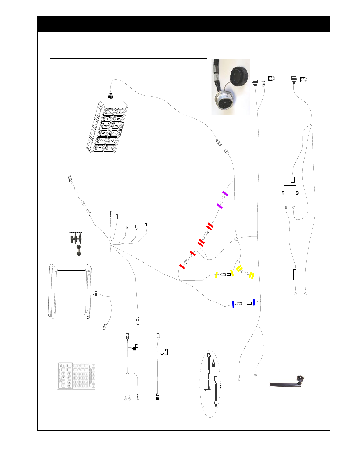
4. Make the following harness connections:
a. Connect X35 harness (3151-45) to the
back of the X35 monitor, refer to Figure
??.
b. Connect Power connector on X35 main
harness (3151-45) to power auxiliary
adapter (3151-69) and connect to 3-pin
AMP auxiliary power connection in the cab
(if exists).
c. If the auxiliary power connection does not
exists in the cab, connect Power connector
on X35 main harness (3151-45) to power
battery adapter (3151-68) and route to
battery and switched power source.
d. Connect RS232-D connector on X35 main
harness (3151-45) to GPS receiver using
appropriate adapter harness.
e. Connect in-cab switchbox harness (3132-
41) into the back of in-cab switch box.
Connect other end to switchbox ISOBUS
adapter harness (3132-42).
f. Connect ISO extension on switchbox
ISOBUS adapter harness (3132-42) to ISO
loop A on X35 harness (3151-45). Connect
other ISO extension on switchbox ISOBUS
adapter harness (3132-42) to ISO loop A
on ISOBUS X35 harness (3151-78).
g. Connect ISO loop B connectors together
on ISOBUS X35 harness (3151-78) and
the X35 harness (3151-45).
h. Connect the switched power lead on
ISOBUS X35 harness (3151-78) to
connector on X35 harness (3151-45).
Connect other lead from ISOBUS X35
harness (3151-78) to SwitchBox power
extension harness (3132-76), then connect
that to switchbox harness (3132-42).
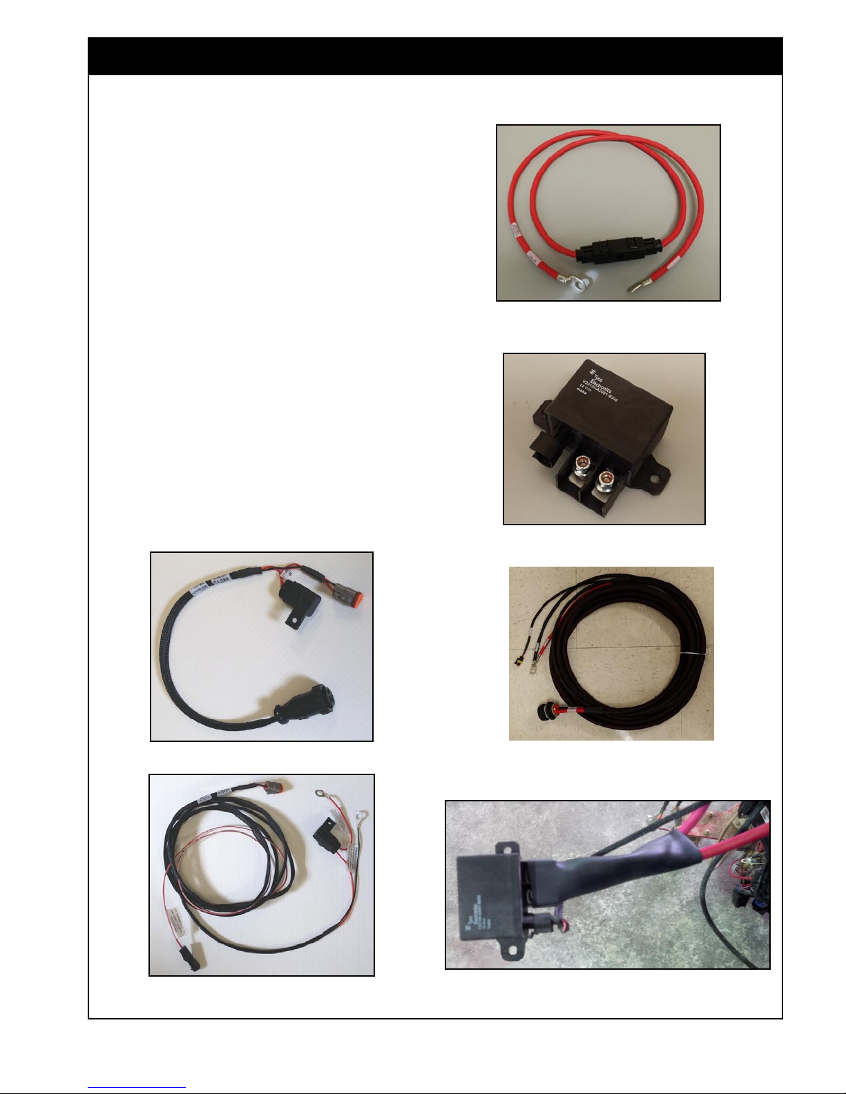
i. Connect the ends labelled "12V Power/
Relay" from 3132-87 & 3132-88 to the
relay 3132-89. Also connect the end
"Power Relay Coil" from 3132-88 to the
3132-89 relay. Install the heat shrink over
the area to protect the exposed wires/posts,
refer to Figure 13.
j. Mount the relay near the battery where it
will be protected and the contacts will not
be shorted.
k. Connect the end labelled 12V Battery "+"
from 3132-87 to positive battery terminal.
l. Connect the end labelled Battery/Frame
Ground from 3132-88 to the negative
battery terminal. Route the other end to the
hitch point and mount using mount plate
(5210-65).
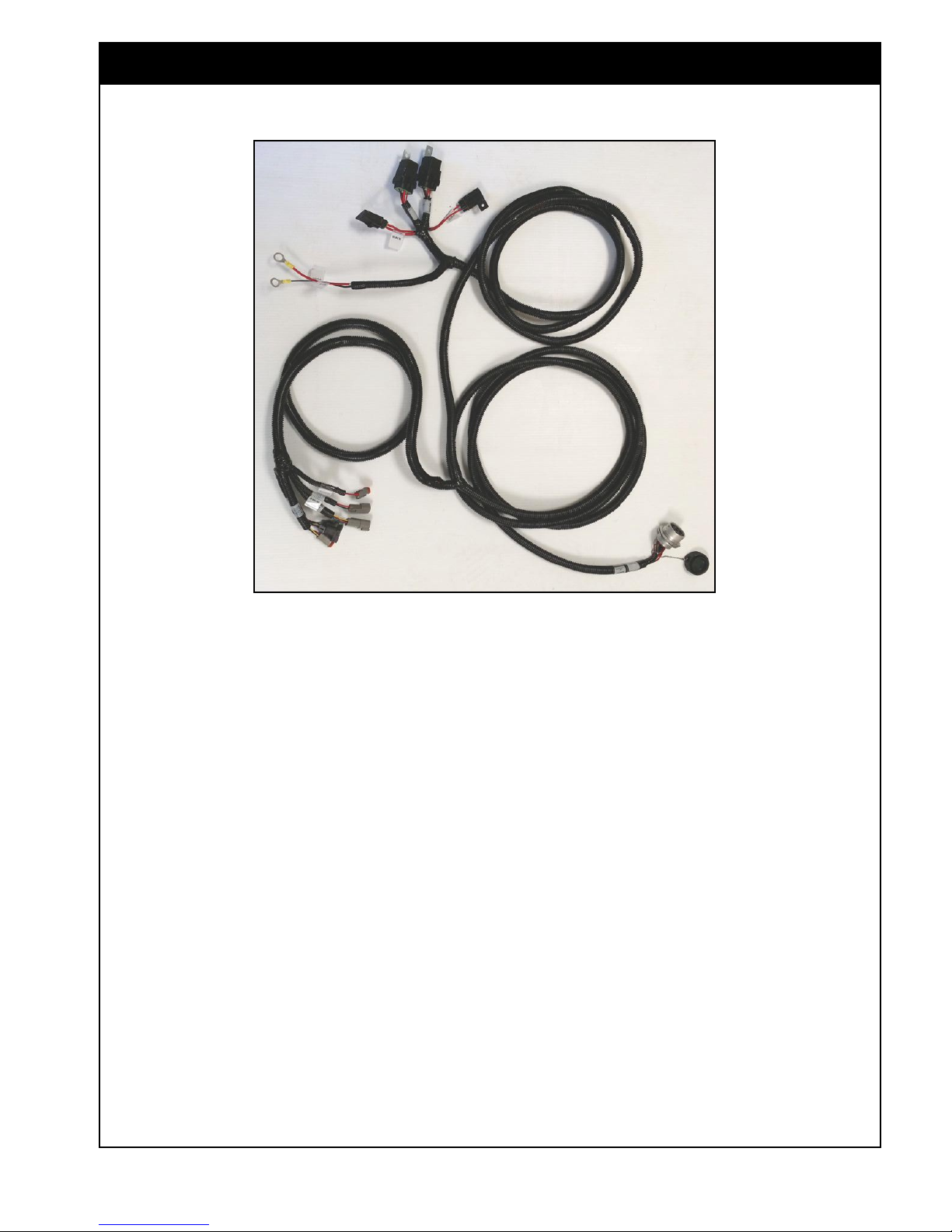
m. Connect ends of ISOBUS X35 harness
(3151-78) to battery. Route other end to
hitch point and mount using plate #5210-
65.

INSTRUCTIONS
7
3 SCHEMATIC - IN-CAB COMPONENTS CONNECTION
UNITS WITH SIMPLIFIED ISOBUS X35 HARNESS #3151-78
X35_2016_INCAB_COMPONENTS_ISOBUS_TRACTOR_B.SKF

INSTRUCTIONS
8
NOTE
FOR ADDITIONAL INFORMATION AND QUESTIONS REGARDING X35 CONSOLE AND GPS SIGNAL REFER TO SERVICE & PARTS
SECTION ON OUR WEB SITE WWW.BOURGAULT.COM
Other manuals for X35
1
Table of contents
Other Bourgault Music Mixer manuals