Boyar-Schultz 6-12 Guide

CareandUseof....
BOYARSCHULTZMODEL6-12
SURFACEGRINDER
CAPACITY-Boyar-SchultzModel6-12Surface
Grinder,a 6 x 12machinewithactually7 inch
crossfeedtravel. . . oneinchmorethantheindi-
cated6 inches.Longitudinaltravelis13inchesand
verticaltravelofspindleis11½inches.
SPINDLE—Thisisthe"workingunit,"theveryheart
ofthemachine,andisdesignedforveryclose
tolerance,smoothfinishgrinding;supportedat
eachendbyover-size,pre-loaded,radialthrust,
superprecisionballbearings.Spindleismotivated
bya special½ H.P.motorandconnectedtomotor
byprecisionmadepulleysandV Belt.Sturdily
built,itwillabsorbtheheavydemandsputupon
itduringa longperiodoftime.
TABLE—Bestmaterial,stressandstrainrelieved.
MadewithoneVeewayandoneFlat,groundand
scrapedforsmoothoperation.
LONGITUDINALTABLEACTION-Obtainedbyconven-
tionalhandwheelandalsobyRapidTraverse
TableLever.Eithermaybedisengagedwhilethe
otherisinuse.LargeHandWheelprovidesextra
leverage.
TABLECARRIAGE—Tabletravelsontwoflatprecision
andhandscrapedways,mountedonmaingrinder
base.Crossfeedtravelisactuatedbyleadscrew
supportedbyballandneedlebearingsandlocated
betweentableways.NeopreneAccordionSleeve
sealsleadscrewfromdirtandabrasivedust.
ACross feed binding screw stopstransversemo-
tionwhendesired.
SPINDLEELEVATINGSCREW-Supportedbyballthrust
bearingsandoperatedbya setofcarefullyselected
bevelgears.Respondsinstantlytoslightestmove-
mentofhandwheelbecauseradialthrustbearing
providesconstanttensionbetweenhandwheel
shaftandverticalscrew.
HANDWHEELS—placedtoaffordgreatestconvenience
andarefittedwithneedlebearingsforeasyopera-
tion.Verticalfeedgraduatedinhalfthousandths;
crossfeedinthousandths.Workingpartenclosed
formaximumprotectionfromabrasivedust.
NEEDLEBEARINGS—Fivesetsofneedlebearingsare
usedinModel6-12SurfaceGrinderforlongwear
andeasyoperation.
OILINGOFTABLES-InkeepingwithBoyar-Schultz
progressivedesigningpolicy,theoilingsystemfor
thelongitudinalandcrossfeedtables,crossfeed
screwandlongitudinalhandwheelhasbeenim-
provedtoeliminate8 of9 oilcups,andatthesame
timeprovideforbetter,morepositiveonepoint
lubrication.(seeillustrationbelow)
ADJUSTABLELIGHT-Fullvisibilityispossiblewith
lightwhichisadjustabletoanyposition.
ShowingtheImprovedoilingsystemdeveloped
forModel6-12SurfaceGrinder.
Wheel Capacity. 7 inch
diameter,½ inchthick-
ness.1¼inchdiameter
holesize.
SpindleElevatingScrew.
Selectedbevelgears,sup-
portedinOilitebearings. ViewShowingthenew
Streamlinedstand.

GENERALINSTRUCTIONS
HANDLING
Removethetopandsidesofthemachinecrate.
Takeoutthescrewsthatsecurethemachineto
thecratebase.
Liftthemachinebymeansofthecrossfeed
handwheelhousingandthetwoliftingstudsfound
onthesides.Liftinginanyothermannermaydam-
agethemachine.Theliftingstudsmaybeun-
screwedwhenthemachineispermanentlysituated.
INSTALLATION
Special
wrenchesaresuppliedwitheachmachinetoadjust
itslegs.Themachinemustbeleveledtopermit
thelubricationsystemtooperateproperly.
Removethegrindertablefromitscrateand
cleanthoroughly.Oilthetablewaysandgreasethe
rackwiththelubricantsrecommendedinthelubri-
cationchart.Cleanthegrindercarriagewaysand
tablepinion.Setthegrindertableinplacegently,
movingitbackandforthuntilthetablepinion
engagestherack.
Loosenthetwowingnutsthatholdthecolumn
reardustcover.Removethedustcoverbysliding
itupward.Cleanthecolumnwaysandlubricate
themwiththesameoilusedonthetableways.
Replacethecolumnreardustcoverandsecure
thewingnuts.
LUBRICATION
Thetableoilcuplubricatesthecrossfeed
screwandthetableandcrossfeedways.Thelarge
oil-cupontopofthecolumncaplubricatesthe
columnways.
Theelevatinghandwheel,rapidtraversehandle
andspindlemotorhavetheirindividualoiling
points.
Followtherecommendationsfoundinthelubri-
cationchartforthelubricationofthemachine.
LUBRICATIONCHART
POSI-
TION
1
2
3
4
5
6
7
8
9
OILING
PERIOD
DAILY
TWICE
WEEKLY
WEEKLY
EVERY
1000
HOURS
DAILY
WHEN
USED
PERMANENT
AFTER6000
OPERATING
HOURS
SEMI
ANNUALLY
SEMI
ANNUALLY
LUBRICATING
INSTRUCTIONS
FILLCUP
FILLCUP
10
TO
20
DROPS
30TO
70
DROPS
LIBERALLY
ATTIMEOF
OVERHAUL
HAND
PACK
3GALS.
HAND
PACK
LUBRICANT
S0C0NYVACUUM
OIL
CO.
VACTRAOIL
HEAVYMEDIUM
"
"
"
"
B.R.B.LIFETIME
GREASE
••
D.T.E.LIGHT
OIL
SQUAREX
GREASE# 1
SHELL
OILCO.
T0NNA
OIL#33
»
•'
•'
"
ALVANIA
GREASE# 2
"
TELLUS
OIL#27
ALVANIA
E.P.GREASE# 2
THETEXAS
OILCO.
CAM0PUS
OIL-D
II
••
"
"
STARFAX
GREASE# 2
••
REGALOIL
A-(RSO)
NOVA
GREASE# 1
2 3
6 4
9
1
5
8
7
under the grinder and grinder stand.

SPINDLE
Thespindlehasbeendesignedandmanufac-
turedtomaintainlongaccuratelife.Itisperma-
nentlygreasepackedandisequippedwithpre-
loaded,superprecisionballbearings.Thespindle
isconnectedtothespindlemotorbymeansofa
"V"belt.Thetensionofthebelthasbeensetat
ourfactory.
Toreadjustthebelttension,removethecolumn
reardustcoverandloosenthefourboltsthathold
themotormountingbrackettothespindlehousing.
Themotormountingbracketmaynowbemoved
upordowntoproducethedesiredbelttension.
Tightenthemountingboltsandreplacethedust
cover.
NOTE:Itisrecommendedthatthespindlebe
sentbacktothefactoryasanassembledunitwhen
repairisdeemednecessary.Inspectionandrepair
isfacilitatedwhenthespindleisreceivedbyusin
thismanner.
TOREMOVESPINDLEHOUSING
ASSEMBLY
(1)Useelevatinghandwheeltomovespindle
verticallytocentrallocationonvertical
column.
(2)Removegrindingwheel,adapter,andwheel
guardfromspindle.Removefrontdust
cover.
(3)Removereardustcover.
(4)Removecoverattopofverticalcolumn.
(5)Driveouttaperpinsecuringelevatinghand-
wheelpiniongeartoelevatinghandwheel
shaftandremovegear.
(6)Remove(4)hex.headcapscrewssecuring
motormountingbracketassemblytospindle.
Liftupassemblytoreleasethemotorpulley
fromthebelt.Carefullyremovemotor
assembly.
(7)Removebeltfromspindlepulley.
(8)Placesupportblocksbetweenloweredgeof
spindleandtiebraceofspindlecolumnat
rearofmachine.Alsoplacesupportblocks
betweenloweredgeofspindlehousingand
tableatfrontofmachine.
(9)Insidetheverticalcolumnunderthebevel
gear,ontheelevatingscrewwillbefound
thethreadedheadelevatingscrewcollar.
Removethesetscrewthatsecuresthecollar
totheelevatingscrew.Youcanthenunscrew
collarandallowtopassoverelevatingscrew
threads.
(10)Attopofcolumn,unscrewhexnutandre-
movebevelgear.IMPORTANT:Caremast
betakentoeliminateallpossibilityofthe
spindlehousingfallingwhileremovingele-
vatingscrew.
(11)Removespindlehousingassemblyfromfront
ofmachine.Donotdisassemblethespindle
unitbeforeshipping,sucha procedurewill
makeitdifficulttodeterminethecauseof
failure.
GRINDINGWHEEL
Thewheelismountedonanadapterwhich,in
turn,ismountedonthespindle.A specialwheel
mountingwrench,furnishedwitheachmachine,
fitsthewheelnutwhichholdsthegrindingwheel
ontheadapterandthenutwhichholdstheadapter
onthespindle.Onegrindingwheelisfurnished
withyourmachine.Thevariousresponsiblemanu-
facturersofgrindingwheelswillgladlygiveyou
informationonspecialwheelneeds.
GRINDINGWHEELADAPTER
Awheelpullerhasbeenfurnishedtoremove
thegrindingwheeladapterfromthespindle.To
removetheadapter,removethewheelnutwith
thespannerwrenchprovidedandscrewthepuller
intothewheeladapter.Tightenthepullera screw
untilthewheeladapterslipsoff.
WETGRINDING
Allmachinesmaybeadaptedforwetgrinding,
butunlessotherwiseorderedthemachineissent
equippedfordrygrindingonly.Informationde-
scribingtheadditionalequipmentrequiredforwet
grindingwillbesentonrequest.
GRINDERTABLE
Thegrindertableisa rugged,closegrained
casting,controlledinhardnessandscientifically
heattreatedtorelieveallinternalstresses.The
tableslidesonhandscrapedways.One"V"and
oneflat.
Thetableworkingsurfacehasbeengroundand
checkedonthemachineitselftoinsureflatnessand
squarenesstothespindle.Thetablewaysare
groovedtopermitproperdistributionofthelubri-
catingoil.
Removeandcleanthetablewaysweekly.

GENERALINSTRUCTIONS
TABLEFEEDHANDWHEEL
Thetablefeedhandwheelisthelargehand-
wheelontheleftfrontofthemachine.Onecom-
pleterevolutionofthishandwheelmovesthetable
3-½".
Movingthehandwheeltransmitsmotionthrough
thetablefeedrackpiniontothetablerackwhich
isfastenedtotheundersideofthetable.Todis-
engagethetablefeedrackpinionfromthetable
rack,pullhandwheeloutward.Whileinthisout-
wardposition,thehandwheelcanbeturnedwith-
outmovingthetable.Thiswillenableyoutoplace
thehandwheelhandleina convenientpositionfor
handlingthedesiredstrokefortheworkyouare
grinding.
AUXILIARYTABLEFEED
(RAPIDTRAVERSELEVER)
Machinesequippedwithauxiliarytablefeed
havetheauxiliarytablefeedleverlocatedatthe
extremeleftofthecrossfeedcarriage.Whennot
inuse,auxiliaryfeedlevershouldbeindown
position.Tomovelevertothisposition,pullout-
ward,swingtotheleftanddown180°.Toutilize
thislever,centerthepartwhichyouintendto
grindundergrindingwheel,disengagetablefeed
handwheel.Toretainhandwheelindisengaged
positionturnhandwheeluntilhandleisinupposi-
tion,pullhandwheeloutwardasfaraspossible,
andturn180°,placinghandleindownposition.
Moveauxiliarytablefeedlevertoa verticalposi-
tionallowingthegeartoengagetherackofthe
table.Theauxiliarytablefeedisdesignedforfast
andaccurategrindingofworkupto6"inlength.
CROSSFEEDTABLECARRIAGE
Thecrossfeedtablecarriagetravelsontwo
groundandscrapedfiatways.Itisguidedand
heldinperfectalignmentbya hardenedandground
rectangularshapedkeywhichismountedinthe
centerontheundersideofthecarriage.Thisrec-
tangularshapedkeymovesbetweena stationary
gibonitsleftsideanda setoftaperedadjusting
gibsonitsrightside.Thegibshavebeenproperly
adjustedfora snugslidingfitatthefactorybut
shouldthenecessityariseforreadjustment,they
maybeadjustedbymeansofthescrewmounted
onthebaseandlocatedjustrightoftherectangular
shapedkey.
CROSSFEEDTABLECARRIAGELOCK
Thismachineisequippedwitha devicefor
lockingthetablecarriageinpositionwhenface
grinding.Youwillfindthecrossfeedtablelock
thumbscrewlocatedontherighthandsideofthe
basedirectlyunderthetablecrossfeedcarriage.
Tighteningthisthumbscrewlockstheadjusting
gibsupagainstthecrossfeedtablekey,prevent-
ingtransversemovement.
IMPORTANT:Thislockmustbereleased
whenoperatingthemachineundernormalcon-
ditions.
CROSSFEEDHANDWHEEL
Thecrossfeedhandwheelislocatedinthe
centeronthefrontofthemachine.Itisgraduated
to(.001").Onecompleteturnwillmovethecross
feedtablecarriage(.100").Thiswheelcontrols
thetransversemovementofthecrossfeedtable
carriage.
ELEVATINGHANDWHEEL
Theelevatinghandwheellocatedatthetopof
thecolumnontherightsideisusedtoraiseor
lowerthespindle.Itisgraduatedinonehalfthou-
sandths(.0005").Onecompleterevolutionraises
orlowersthespindle(.050").
Iftheelevatinghandwheelrotatestoofreely,it
canbeadjustedfortheproperrotatingtensionby
meansofthetensionadjustingdevicedesignedfor
thispurpose.Togainaccesstothisadjustment
removethe(4)flatheadscrewssecuringthe
columncovertothecolumn.Justtotherearand
rightofthehandwheel,youwillfindthesocket
headadjustingscrew.Toincreasethetensionon
thehandwheelturnclockwise.Todecreasethe
tensionturncounterclockwise.
VERTICALFEEDGEARS
Removecoverfromtopoftheverticalcolumn.
Thepinionissecuredtoelevatinghandwheelshaft
justbelowthebevelgearandbacklashisadjusted
bymeansofa lockingcollar.


BOYAR-SCHULTZ6-12HYDRAULICSURFACEGRINDER
SeeBoyar-Schultzinstructionsforthehandfeed
model6-12surfacegrinderbeforeremovingthe
machinefromitscrate.Followinstructionsgiven
intheparagraphsdescribinghandling,installation
andlubrication.
HYDRAULICRESERVOIR
Thehydraulicpumpandthepumpmotorare
housedinthelowersectionofthehydraulicreser-
voir.Thepumpmotormustbeconnectedtothe
starterswitch.Thisisdonebyconnectingthe
multi-wiredcablethatextendsfromtherearof
thereservoirtothejunctionboxlocatedonthe
backofthegrinder.A fourwirecableisfurnished
forthreephaseinstallation.Matchuploosewires
bythecolorcode,secureeach,andinsulate.The
greenwireshouldbefastenedtotheclampscrew
insidethejunctionboxtocompletetheground.
Athreewirecableisfurnishedforsinglephase
installation.Matchupcolorcodedwiresand
groundthegreenwirestothejunctionboxclamp
screw.
Twohosesarefurnishedwiththemachine.The
intakehose(longhose)shouldbeconnectedtothe
lowerofthetwoelbowsthatprotrudefromthe
reservoir,tothefrontelbow,locatedontheright
sideofthegrindercarriage.Theexhausthose
(shorthose)shouldbeconnectedtotheupper
reservoirelbowandtotherearcarriageelbow.In
bothcases,tightenthehosetothecarriageelbows
first.Stationreservoironthefloorasshownin
accompanyingliterature.Thebackofthereservoir
shouldbeapproximatelyflushwiththebackofthe
grinderstand.
Removetopcoverofthereservoirandaddthe
threegallonsofhydraulicoilthatarefurnished
withthemachine— seeLubricationChartfor
recommendedoils.Thelevelofthehydraulicoil
shouldnotbepermittedtodropbelowthetopof
thefilterscreen.Toinsurelong,trouble-freeopera-
tionofthishydraulicmachine,thehydraulicoil
shouldbechangedeverysixmonths.Thereservoir
andthefilterscreenshouldbecleanedatthetime
oftheoilchange.
AUTOMATICOPERATION
Thestopdog,locatedonthefrontedgeofthe
grindertable,controlthelongitudinaltravelofthe
table.Thestopdogsmaybeadjustedbymeansof
a5/32"hexwrenchtosuitthelengthofstroke
desired.Thedogsmustbesetsothatthepilot
valvehead(thetwoprongedcastinglocatedonthe
topofthevalvebody)islocatedbetweenthem.
Thestopdogtotherightofthevalvemuststrike
theupperarmofthepilotvalveheadandthestop
dogtotheleftmuststrikethelowerarm.For
initialoperationofthemachine,thestopdogs
shouldbesetapproximatelysixinchesapart.
Connectcylinderrodtotableadapterhousing.
Thetableadapterhousingislocatedontheunder-
sideofthetableatitsrightend.Toengagethe
cylinderrod,raisethepinthatprotrudesfromthe
housingandinserttheballendofthecylinderrod.
Oscillatethetablehandwheelwhileexertinga
slightdownwardpressureontheadapterhousing
pinuntilthecylinderrodislockedintoplace.
Beforeoperatingthemachinehydraulically,the
tablehandwheelmustbedisengaged.Pulloutthe
knoboftheplunger,locatedontheleftsideofthe
carriage,andpulloutthehandwheel.Release
plungertolockhandwheelinthe"OUT"position.
CAUTION!
Checktoseethatthegrindingwheelclearsthe
workandthatthemagneticchuckisenergized.
Thestarterswitchislocatedontherightsideof
thegrinderbase.Theswitchhasthreepositions,
"MANUAL","OFF"and"AUTO".Tostart
spindleandhydraulicpumpmotor,placeswitch
intothe"AUTO"position.Tosetthetablein
motion,turntheshut-offvalvehandle(locatedon
topofthevalve)inthedirectionindicatedbythe
arrow.
Erraticactionofthetableinitsinitialoperation
orafterprolongedidlenessisduetoairinthe
hydraulicsystem.Theairwillworkoutandthe
actionwillimproveaftera shortrun-inperiod.
MANUALOPERATION
Placeshut-offvalveinthe"OFF"positionand
setstarterswitchinthe"MANUAL"position.
Manualoperationofthelongitudinaltablefeedis
simplifiedifthecylinderrodisdisengagedfromthe
table.Todisengagethecylinderrod,raisethepin
thatprotrudesfromtheadapterhousingandmove
thetabletotheright,allowingthepintodropafter
thecylinderrodisclearoftheadapterhousing.
Cylinderroddisengagementisrecommendedonly
whenprolongedmanualuseisanticipated.
TABLECUSHIONADJUSTMENT
Aneedlevalveadjustmenthasbeenprovided
ontherightsideofthemainvalvetocushionthe
tablereversals.Toadjust,loosenthelocknutand
screwtheneedlevalveintoincreaseoroutto
decreasethecushion.
Thisadjustmenthasbeenmadeatthefactory
andanyre-adjustmentshouldonlybemadeafter
therigidmountingofthemachinehasbeen
checked.

SPECIFICATIONS(6-12)FOR6x12HANDFEEDANDHYDRAULICSURFACEGRINDERS
HydraulicFeedHandFeed
TableTravel
Longitudinal
CrossFeed
WorkHeight(using7"diam.wheel)
TableWorkingSurface
("T"slot," width)
13"
7"
0"to11¼"
12"x 5 "
13"
7"
0"to11¼"
12"x 5 "
GrindWheel
Diameter
Thickness
HoleDiam.
Weight
Net
Shipping
7"
3/16"to½"
1¼"
485lb.
705lb.
7"
3/16"to½"
1¼"
SpindleSpeed
HandwheelGraduation
Vertical
CrossFeed
LongitudinalTableSpeed
SpindleMotor
HydraulicPumpMotor
FloorSpace
Height
(BenchModel)
(FloorModel)
3000rpm
.0005"
.001"
0-50fpm
½hp—3450rpm
¼hp-1725rpm
44"x 38"
32"
62"
3000rpm
.0005"
.001"
½hp—3450rpm
43"x 38"
32"
62"
415lb.
561lb.
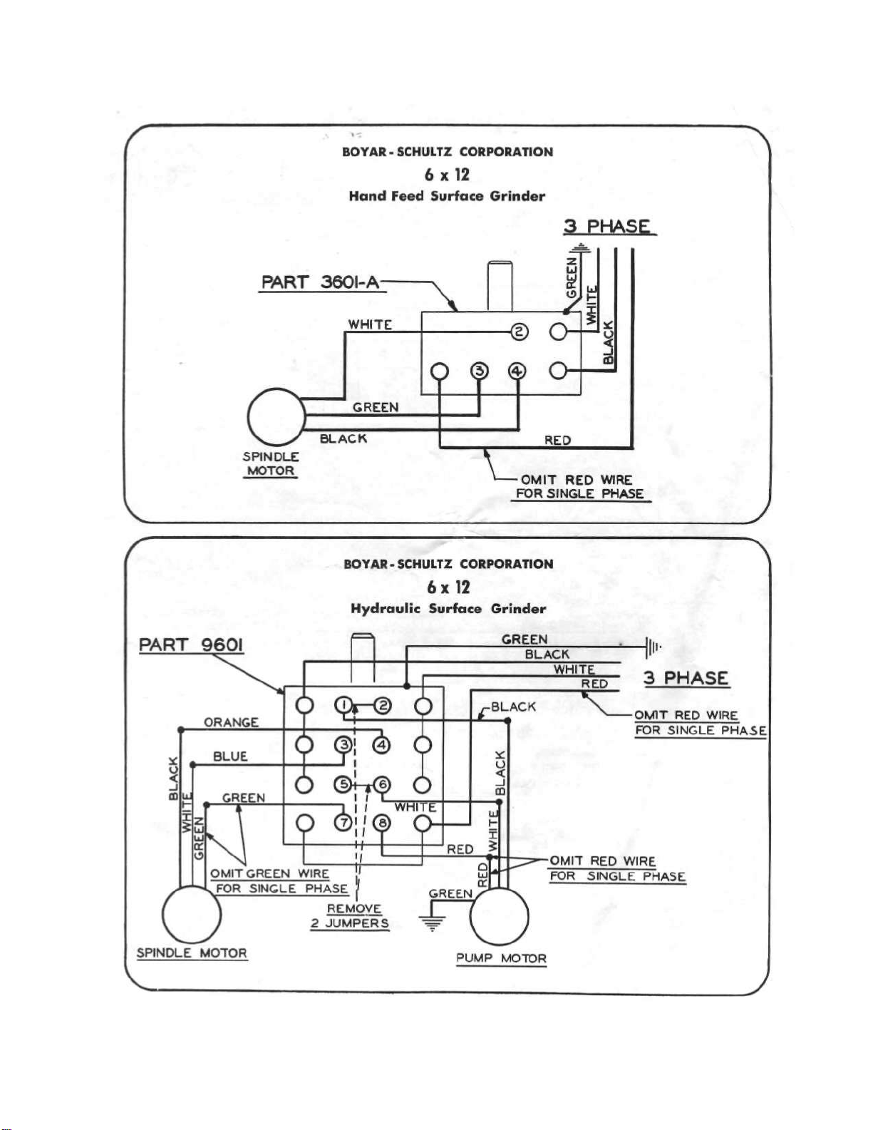
ELECTRICALEQUIPMENT
Themotorfurnishedwiththismachineisa ½
H.P.,220volt,3 phase,60cycle,3450RPM,open
roundframe,sleevetypebearingmotor,precision
balanceddynamicallyforsmoothandvibration-
freeoperation.Witha minimumamountofcare,
motorshouldlastthelifeofthegrinder.Follow
lubricationchartexplicitlyforlubricatingthisunit.
Machinescanbewiredfor110V - 60cycle- 1
phaseor220V - 60cycle- 3 phase.Theyare
equippedwith300Voltwire.Machineswiredfor
440V - 60cycle- 3 phase— have600Voltwire.
Themachineiswiredfor220volt,3 phase,60
cycleoperationunlessotherwisespecified.(See
Fig.2 andFig.3}
Ifthemachineisequippedwiththeadjustable
bracketlamp,thelampissuppliedwithextension
cordfor110voltcircuit.
OPTIONALACCESSORIES
1.Metalpedestalbase.
2.Adjustablelongitudinaltablestops.
3.Rapidtraverseleverarm.
4.Mountedadjustableelectriclight.
5.5"x 10"Walkerpermanentmagneticchuck.
6.6"x 12"Walkerpermanentmagneticchuck.
7.Hanchett5"x 10"Magna-Lockelectricmag-
neticchuckcompletewithrectifier.
8.Hanchett6"x 12"electricmagneticchuck
completewithrectifier.
9.Diamondholderforwheeldressing.
10.Mounteddiamondtofitholder.
11.Wetgrindingsplashguard.
12.Coolanttankandpump.
13.Motorsavailable:
110volt,60cycle,singlephase(standard)
220volt,60cycle,threephase(standard)
440volt,60cycle,threephase(special)
14.Dustcollectorcompletewithnozzle.

NOTE:AssemblePartsinRelationshipShown.
REPLACEMENTPARTSLIST
NotShownonValveAssembly
9600
96O0-A
9600-X
9601
9603
9603-A
9604
9606
9608-A
9609
9609-A
9613
9618
HydraulicPumpandMolarUnit— 3 Phase220/440Volt
HydraulicPumpandMalarUnit—1Phase115/230Vail
HydraulicPumponly
DrumSwitch
HydraulicCylinder
HydraulicCylinderChevronPacking
HydraulicReiervoirFilter
IntakeHas*(LongHoiel
IntakeHoie(LongHose)forMath/notw/fftJ.I.C. EJecfricafControls
ExhaustHaie(ShortHose)
ExhaustHot*(ShortHotelforMachine*with J.I.C. ElectricalControls
HoseCoupling
FilterlineHose(5"Long)
Table of contents
Popular Grinder manuals by other brands

RODEX
RODEX RDX1031 instruction manual

Bosch
Bosch Professional GWX 18V-15 SC Original instructions

Ingersoll-Rand
Ingersoll-Rand Power Force PF450 instructions

Osaki Power Tools
Osaki Power Tools GB150-2 Operator's manual

SUHNER ABRASIVE
SUHNER ABRASIVE UWG 10-R125 Technical document

Expobar
Expobar PULSE 65 user manual


