Boyles Fitness 3 IN 1 ROWER User manual
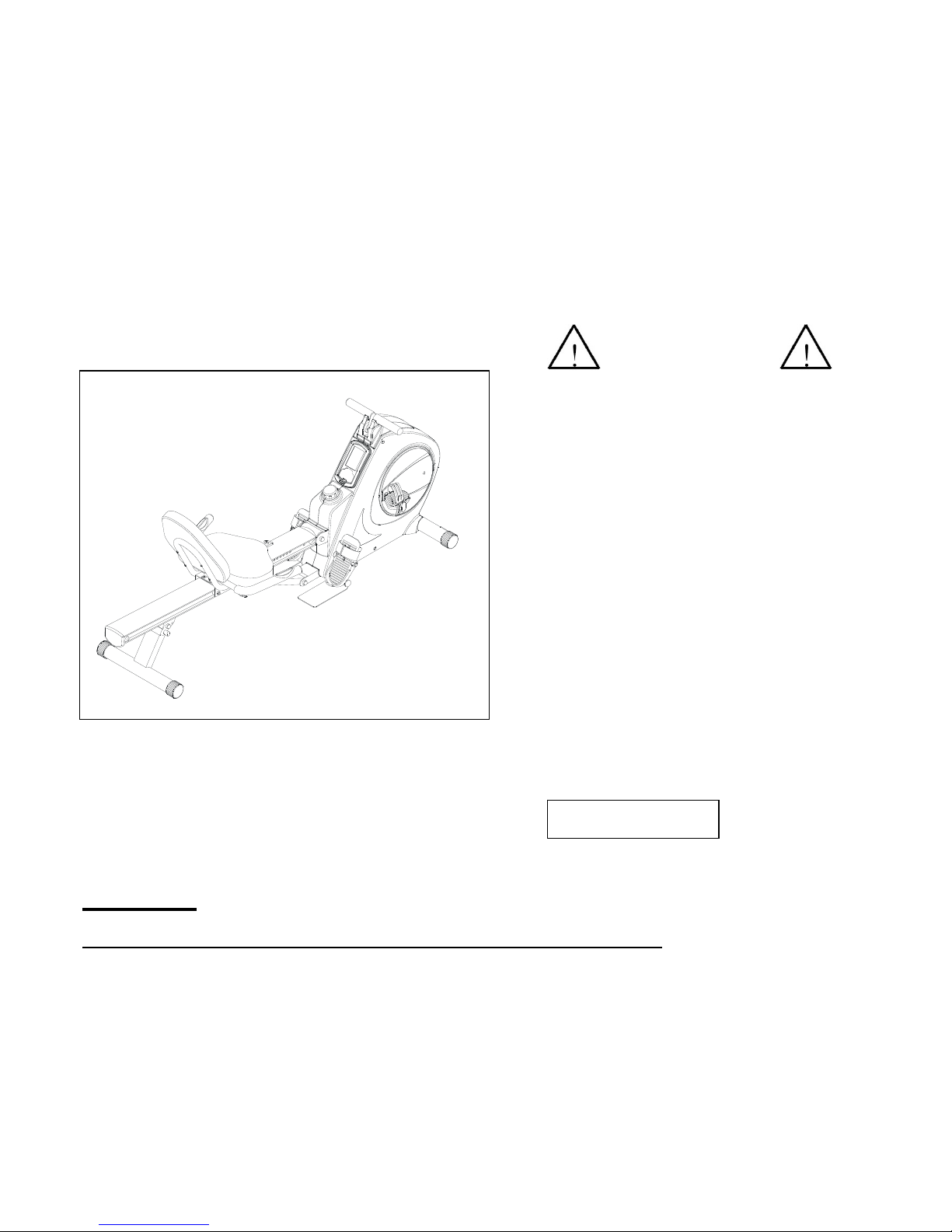
3 IN 1 ROWER / RECUMBENT BIKE
& STRENGTH TRAINER
OWNER’S MANUAL
CAUTION:
Max user weight on this product should not exceed 125kgs.
Product May Vary Slightly From Pictured.
v. IV
Exercise can present a health risk.
Consult a physician before beginning
any exercise program with this
equipment. If you feel faint or dizzy,
immediately discontinue use of this
equipment. Serious bodily injury can
occur if this equipment is not assembled
and used correctly. Serious bodily injury
can also occur if all instructions are not
followed. Keep others and pets away
from equipment when in use. Always
make sure all bolts and nuts are
tightened prior to each use. Follow all
safety instructions in this manual.
MADE IN TAIWAN
WARNING

2
SAFETY INSTRUCTIONS
WARNING: To reduce the risk of serious injury, read the following Safety Instructions before using
the 3 IN 1 Rower / Recumbent Bike & Strength Trainer.
1. Read all warnings posted on this product.
2. Read this Owner’s Manual and follow it carefully before using this machine. Make sure that it is properly
assembled and tightened before use.
Keep children away from the 3 IN 1 Rower / Recumbent Bike & Strength Trainer. Do not allow children to use
or play on the 3 IN 1 Rower / Recumbent Bike & Strength Trainer. Keep children and pets away from the
3 IN 1 Rower / Recumbent Bike & Strength Trainer when it is in use.
4. Set up and operate the 3 IN 1 Rower / Recumbent Bike & Strength Trainer on a solid level surface. Do not
position on loose rugs or uneven surfaces.
5. Inspect the 3 IN 1 Rower / Recumbent Bike & Strength Trainer for worn or loose components prior to use.
6. Tighten / replace any loose or worn components prior to using this machine.
Make sure the Rear Support (62) is locked properly with the Pull Pin (63) before using 3 IN 1 Rower /
Recumbent Bike & Strength Trainer.
8. Make sure the Rail (52) is locked properly by the Release Knob (59) located on the Support Tube(56) when
in storage.
9. Keep fingers clear of all pinch points when folding and unfolding the 3 IN 1 Rower / Recumbent Bike &
Strength Trainer.
10. Lock seat in position with at least one adjustment hole visible in front of the seat before lifting rail to
storage position. This will prevent the seat from damaging the covers.
11. Consult a physician prior to commencing an exercise program. If, at any time during exercise, you feel faint,
dizzy, or experience pain, stop and consult your physician.
12. Follow your physician’s recommendations in developing your own personal fitness program.
13. Always choose the workout which best fits your physical strength and flexibility level. Know your limits and
train within them. Always use common sense when exercise.
14. Do not wear loose or dangling clothing while using this 3 IN 1 Rower / Recumbent Bike & Strength Trainer.
15. Never exercise in bare feet or socks; always wear correct footwear, such as running, walking, or
cross-training shoes. Be sure that they fit well, provide foot support and feature non-skid rubber soles.
16. Be careful to maintain your balance while using, mounting, dismounting, or assembling the 3 IN 1 Rower /
Recumbent Bike & Strength Trainer, loss of balance may result in a fall and serious bodily injury.
17. The 3 IN 1 Rower / Recumbent Bike & Strength Trainer should not be used by persons weighing over 125kgs.
18. The 3 IN 1 Rower / Recumbent Bike & Strength Trainer should be used by only one person at a time.
19. The 3 IN 1 Rower / Recumbent Bike & Strength Trainer is for domestic consumer use only. It is not for use in
public or semipublic facilities.
WARNING: Before starting any exercise or conditioning program you should consult with your personal
physician to see if you require a complete physical exam. This is especially important if you are over the age of
35, have never exercised before, are pregnant, or suffer from any illness. READ AND FOLLOW THE SAFETY
PRECAUTIONS. FAILURE TO FOLLOW THESE INSTRUCTIONS CAN RESULT IN SERIOUS BODILY
INJURY.
3
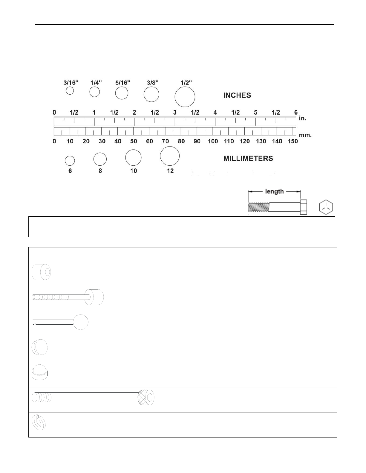
HAREWARE INDETIFICATION CHART
This chart is provided to help identify the hardware used in the assembly process. Place the washers, the end of the bolts,
or screws on the circles to check for the correct diameter. Use the small scale to check the length of the bolts and screws.
NOTICE: The length of all bolts and screws except those with flat heads is measured from
below the head to the end of the bolt or screw. Flat head bolts and screws
are measured from the top of the head to the end of the bolt or screw.
After unpacking the unit, open the hardware bag and make sure that you have all the following items. Some hardware
may be already attached to the part.
Part No. and Description Qty
53 Stopper 1
54 Stopper Bolt 1
63 Pull Pin 1
78 Round Plug 25mm 2
79 Nut Cap (M10) 8
81 Bolt, Socket Head (M8x1.25x70mm) 2
89 spring washer 2

4
HAREWARE INDETIFICATION CHART
Part No. and Description Qty
94 Bolt, Button Head (M8x 1.25x 15mm) 3
95 Bolt, Hex Head (M6x 1 x 15mm) 4
96 Bolt, Hex Head (M6x1x30mm) 4
97 Bolt, Hex Head (M8x1.25x16mm) 4
101 Bolt, Hex Head(M10x1.5x85mm) 1
102 Bolt, Hex Head(M10x1.5x95mm) 1
103 Bolt, Hex Head(M10x1.5x125mm) 1
105 Nylock Nut(M10x1.5) 3
109 Large Washer (M8xφ23) 2
114 Bolt, Button Head(M8x1.25x12mm) 4

5
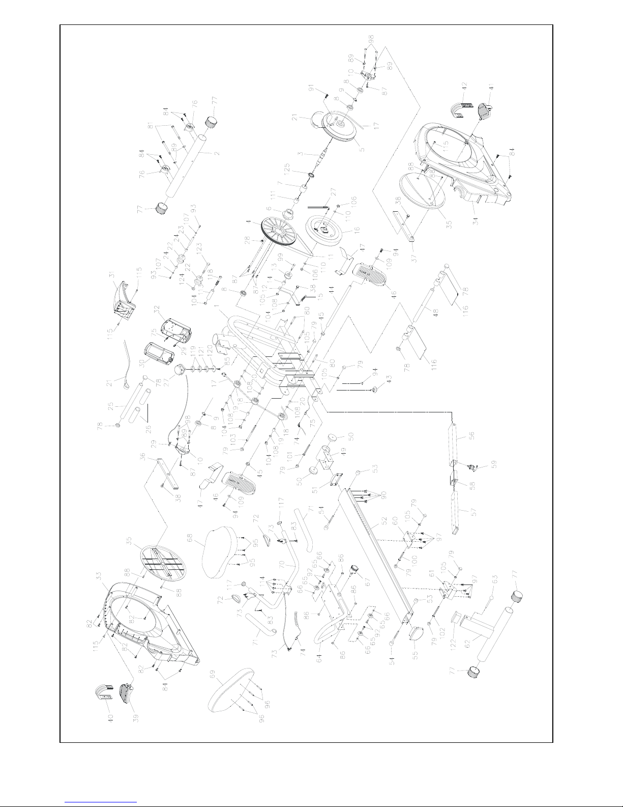
ASSEMBLY INSTRUCTIONS
Place all parts form the box in a cleared area and position them on the floor in front of you. Remove all packing
materials from your area and place them back into the box. Do not dispose of the packing materials until
assembly is completed.
STEP 1: There is an “R” decal on one end of the FRONT STABILIZER (2). Attach the FRONT
STABILIZER (2) onto the MAIN FRAME(1) with the “R” decal end at right side and secure
with the Bolt, Socket Head (M8x70mm) (81) and the SPRING WASHER M8 (89).
STEP 2: Insert the STOPPER TUBE (48) through the MAIN FRAME (1) and secure with the BOLT,
BUTTON HEAD (M8x15mm) (94).
STEP3: Place the RIGHT PILATES PEDAL (116R) onto the STOPPER TUBE (48). Press the Round
Plug 25mm (78) into the end of STOPPER TUBE (48); repeat the same step in the left side.
NOTE: The PEDAL STRAPS (47) are pre-assembled to the FOOT PEDALS (46). The pedal and
strap assembly for the left side has an “L” decal. The pedal and strap assembly for the right
side has an “R” decal.
STEP 4: Insert the PEDAL SHAFT (44) through the MAIN FRAME (1). Place the RIGHT FOOT
PEDAL ASSEMBLY (46R) onto the right end of the PEDAL SHAFT (44) and place the LEFT
FOOT PEDAL ASSEMBLY (46L) onto the left end. Secure the FOOT PEDALS with BUTTON
HEAD BOLTS (M8x15mm) (94) and LARGE WASHERS (M8)(109) at both ends of the
PEDAL SHAFT (44).
NOTE: You need to use two Allen Wrenches to tighten the BUTTON HEAD BOLTS (M8x15mm)(94)
at both ends of the PEDAL SHAFT(44) at the same time.
6
ASSEMBLY INSTRUCTIONS
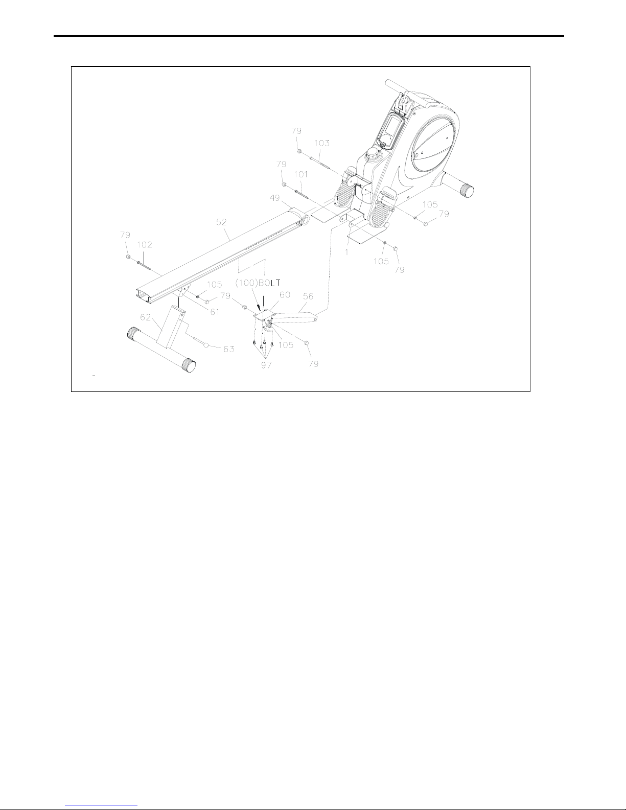
STEP 5: Attach the SUPPORT BRACKET (60) onto the RAIL (52) with HEX BOLTS (M8x16mm) (97).
Press the NUT CAPS (79) onto the NYLOCK NUT (M10) (105) and the HEX BOLT
(M10x75mm) (100).
STEP 6: Attach the RAIL (52) onto the MAIN FRAME (1) by sliding the RAIL PIVOT (49) into the
bracket on the MAIN FRAME (1) and securing with the HEX BOLT (M10x125mm) (103) and
the NYLOCK NUT (M10) (105). Press the NUT CAPS (79) onto the HEX BOLT
(M10x125mm) (103) and NYLOCK NUT (M10) (105).
STEP 7: Connect the lower end of the SUPPORT TUBE (56) to the MAIN FRAME (1) with HEX BOLT
(M10x85mm)(101) and NYLOCK NUT(M10)(105). Press the NUT CAPS (79) onto the HEX
BOLT (M10x85mm) (101) and the NYLOCK NUT (M10)(105).
STEP 8: Attach the REAR SUPPORT (62) into the REAR SUPPORT BRACKET (61) located on the
RAIL(52) with the BOLT, HEX HEAD (M10x95mm) (102) and the NYLOCK NUT (M10) (105).
Lock the REAR SUPPORT (62) in position with the PULL PIN (63). Press the NUT CAPS (79)
onto the BOLT, HEX HEAD (M10x95mm) (102) and the NULOCK NUT (M10) (105).
7
ASSEMBLY INSTRUCTIONS
NOTE: Be careful not to damage the PULSE SENSOR WIRES (73,74) while doing assembly
STEP 8 to STEP 10.
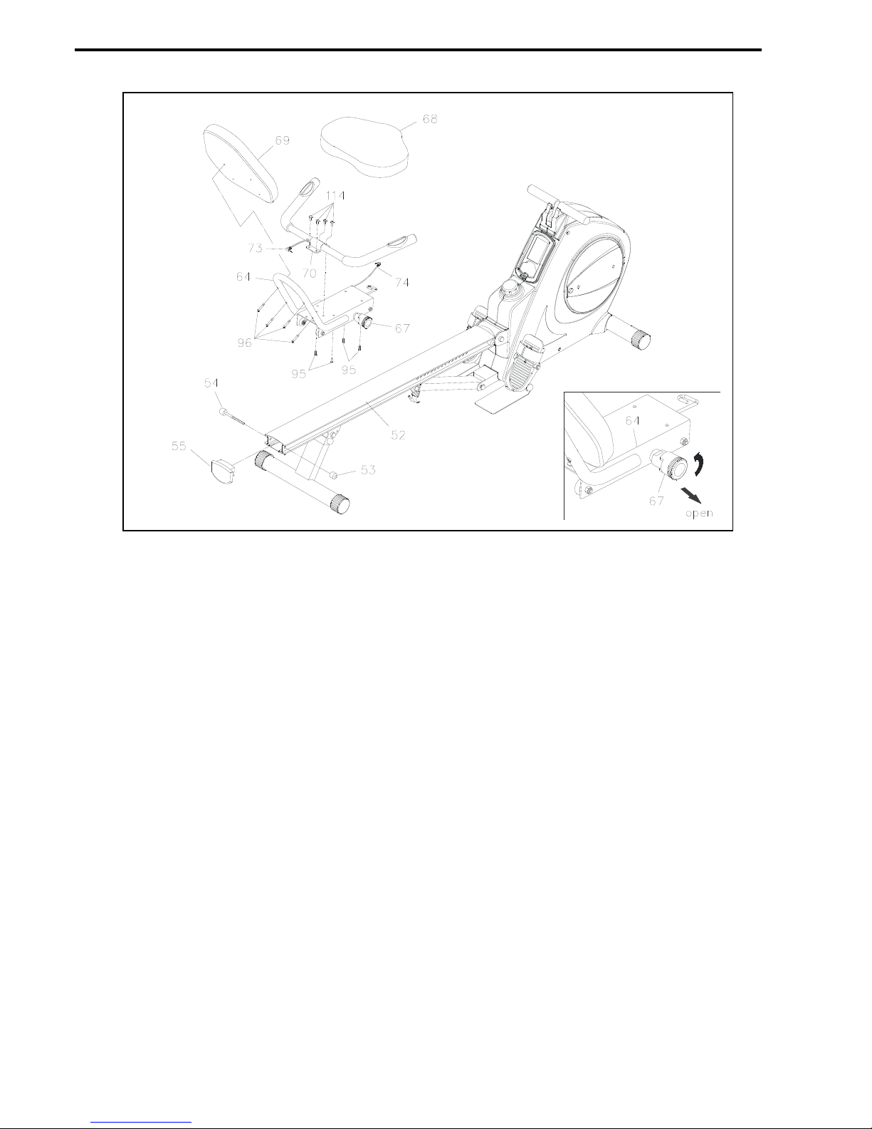
STEP 9: Attach the HANDRAIL (70) onto the SEAT CARRIAGE (64) with BUTTON HEAD BOLTS
(M8x12mm) (114).
STEP 10: Attach the SEAT (68) onto the SEAT CARRIAGE (64) with the BOLT, HEX HEAD
(M6x1x15mm) (95). Attach the BACK CUSHION (69) onto the SEAT CARRIAGE (64) with
HEX HEAD BOLTS (M6x1x30mm) (96).
STEP 11: Turn the knob of the SPRING PIN (67) counter-clockwise and lock the knob in the release
position, refer to the inset drawing. Slide the SEAT CARRIAGE ASSEMBLY (64) onto the
RAIL (52). Press the RAIL CAP (55) into the back end of the RAIL (52). Insert the
STOPPER BOLT (54) through the RAIL (52) and RAIL CAP (55) to bolt them together with
the STOPPER (53). Please verify that the other STOPPER BOLT (54) at the front end of
RAIL (52) was assembled at the factory.

8
ASSEMBLY INSTRUCTIONS
STEP 12: Thread the RIGHT PEDAL (41) onto the RIGHT CRANK (37) located at inside of the
CRANK COVER (35) as the photo shown. Tighten the pedal securely. Select the RIGHT
PEDAL STRAP (42) which has R decal marked on the bottom side of the strap. Snap the
three hole end onto the inside edge of the RIGHT PEDAL (41). Snap the other end onto the
outside edge of the RIGHT PEDAL (41) with the R decal mark on the bottom of the RIGHT
PEDAL STRAP (42). Select adjustment holes which allow your foot to be easily removed
from the pedals. Do the same way on the left side.
STEP 13: Refer to the inset drawing. Plug the PULSE SENSOR WIRE (73) into the preset socket of
the PULSE COIL WIRE (74) located on the SEAT CARRIAGE (64). Plug the PULSE COIL
WIRE (74) into the preset socket of PULSE CONNECTION WIRE (75) located on the
bracket on the MAIN FRAME (1).
STEP 14:
a. A bottle of silicone is packed together with user’s manual.
b. Gently apply the silicone to the rollers sliding path
(inner upper side and inner bottom side) on the aluminum rail.
Note: Apply liberally but be cautious not to spill the lubricant as
applied surfaces will become very slippery. To clean spills use
warm soapy water, repeat if necessary.
c. Then slowly slide the Seat forward and backward for a few seconds
allowing the lubricant spread evenly on the rollers sliding path on
aluminum rail.
NOTE:
The RIGHT PEDAL (41)
has Rdecal stamped on
the end of the right pedal
shaft. The RIGHT
PEDAL (41) has right hand
threads and is tightened by
turning clockwise. The LEFT
PEDAL (39) has Ldecal
stamped on the end of the left
pedal shaft. The LEFT
PEDAL (39) has
left hand threads and is
tightened by turning
counter-clockwise.
Lubricate the silicone to
the rollers sliding path on
the aluminum rail.
9
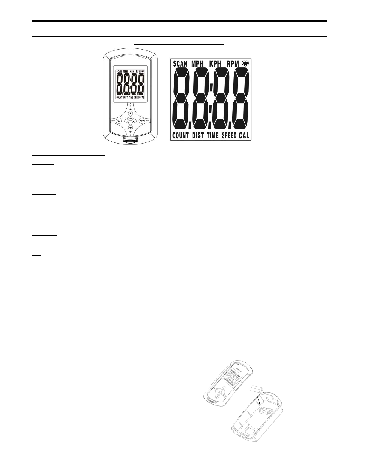
USING THE ELCETRONIC METER- 81338
USING THE ELECTRONIC METER
KEY GUIDE:
MODE:
1.Select function to be preset. DIST, TIME, SPEED, CAL, PULSE.
2.Select function to display on the screen. TIME-SPEED-CAL-PULSE-DIST.
RESET:
1.Hold two seconds to reset all of the values to zero.
2.During the setting mode, press this button to clear the setting values to zero.
3.During the stop mode, press this button to clear the values on the display to zero.
ENTER:
Press this button to enter setting mode.
UP
Increase the setting value of the following functions: TIME-CAL-PULSE-DIST.
DOWN
Decrease the setting value of the following functions: TIME-CAL-PULSE-DIST.
HOW TO INSTALL BATTERIES:
1. Take off the top cover of meter.
2. Place two pieces of SIZE-AA or UM-3 batteries into the battery housing.
3.Insure batteries are correctly positioned and battery springs are in proper contact with batteries.
4.If the batteries power is insufficient, please change batteries immediately.
5.If the display is illegible or only partial segments appear, please remove the batteries and wait
for 15 seconds before reinstalling.
6.Removing the batteries will erase monitor's memory.
NOTE:
1. Do not mix a new battery with an old battery.
2. Use the same type of battery. Do not mix an alkaline
battery with another type of battery.
3. Rechargeable batteries are not recommended.

10
USING THE ELCETRONIC METER- 81338
FUNCTION AND OPERATION:
AUTO ON/OFF
The monitor will start up automatically if the exercise machine is in motion. If stop exercising for
over 4 minutes, monitor will turn off and reset all function values to zero.
KPH
The unit for the speed is kilometer per hour. The unit for distance is kilometer.
MPH
The unit for the speed is mile per hour. The unit for distance is mile.
SCAN
Press the MODE button until SCAN display on the screen. Automatically scans TIME-SPEED
-CAL-PULSE-DIST in sequence with a change every six seconds.
TIME
Press the MODE button until TIME display on the screen. Monitor will display the time values on
the screen.
Count up: Counts upward to 99:59 in one second increments once the meter is turned on.
Count down: Setting the exercise time from 0:00-99:00, the monitor will count down from preset
values. Once reach setting value, monitor will alarm.
SPEED
Press the MODE button until SPEED displays on the screen. Monitor will display the current
speed values from 0.0 to 99.9 km or mile on the screen.
CALORIE
Press MODE button until CAL display on the screen. Monitor will display the calorie consumption
values on the screen.
Count up: Without setting the calorie value, the monitor will count up the values from 0.0 to 999.9
kcal.
Count down: Setting the calorie value from 0.0 to 999.0 kcal, the monitor will count down from
preset values, Once reach setting value, monitor will alarm.
The calorie readout is an estimate for an average user. It should be used only as a comparison
between workouts on this unit.
DISTANCE
Press MODE button until DIST display on the screen. Monitor will display the distance values on
the screen.
Count up: Without setting the distance value, the monitor will count up the values from 0.0
to 999.9 km or mile.
Count down: Setting the distance values from 0.0 to 999.9 km or mile, the monitor will count
down from preset values. Once reach setting value, monitor will alarm.
PULSE
Press MODE button until display on the screen.
The monitor will display your current pulse rate in beats per minute.

11
USING THE ELCETRONIC METER- 81338
To display pulse, select the PULSE MODE and grasp the pulse sensors on the handrail, one
in each hand. The heart icon will flash when the meter senses your pulse. Your pulse will be
displayed approximately five seconds after the heart icon is displayed. If the heart icon does
not appear, relax your grip or change your grip on the pulse sensors.
If you preset the PULSE value, the meter will warn you with an audible alarm when your
pulse exceeds the set value. Stop exercising until your pulse comes down.

12
OPERATIONAL INSTRUCTIONS
RECUMBENT BIKE MODE AND ROWER MODE
Your 3 IN 1 Rower/Recumbent Bike & Strength Trainer can be used in the Recumbent Bike mode or
the Rower mode. When the SPRING PIN (67) locks the SEATASSEMBLY to the RAIL (52), the Rower,
Recumbent Bike & Strength Trainer is in the Recumbent Bike mode. When the SPRING PIN (67) is in
the Release position, the SEAT ASSEMBLY
is not locked to the RAIL (52) and the
Rower, Recumbent Bike & Strength Trainer
is in the Rower mode.
RECUMBENT BIKE MODE: Pull the knob
on the SPRING PIN (67), turn it clockwise
and release the knob to allow it to lock the
seat in position. Sit on the seat and pedal
with the PEDALS (39,41).
ROWER MODE: Pull the knob on the
SPRING PIN (67) and turn it counter-clockwise to lock it in the release position. Refer to the inset
drawing. This will allow the SEATASSEMBLY to slide freely on the RAIL (52). To workout, sit on the
seat, place your feet on the fixed FOOT PEDALS (46) and pull on the HANDLEBAR (25).
NOTE: If the FRONT STABILIZER(2) raises off the floor during use, adjust the STAND(43) to a higher
position.
CAUTION: Always verify that the SPRING PIN (67) is in the correct position before you begin your
workout.
SEAT ADJUSTMENT
Proper seat adjustment is important for Recumbent Bike mode.
1. Pull the knob on the SPRING PIN (67) and slide the SEATASSEMBLY forward or backward to
adjust the seat. Release the knob on the SPRING PIN (67) and make sure it is inserted into one of
the adjustment holes in the RAIL (52).
2. Sit on the seat and place your feet on the
pedals. You should be able to move through a
complete pedal stroke without locking your
knees or shifting your hips on the seat. The
seat is too close to the pedals if you have
more than a slight bend in your knees at the
bottom of the pedal stroke. The seat is too far
from the pedals if you have to completely
straighten your knees at the bottom of the pedal stroke. Refer to the illustrations below.
WARNING: Do not attempt to adjust the seat while you are on the 3 IN 1 Rower/Recumbent Bike & Strength
Trainer.

13
BODY MOVEMENT EXERCISE
RECUMBENT EXERCISE BUTTOCKS EXERCISE
BICEPS CURL EXERCISE
ABDOMINAL EXERCISE
ROWER EXERCISE
SINGLE ARM BICEP CURL
LEG EXTENSION EXERCISE LEG STRETCH EXERCISE
Be sure to step on the Steel PEDAL
Be sure to step on the Steel PEDAL
Be sure to step on the Steel PEDAL
Be sure to step on the Steel PEDAL

14
OPERATIONAL INSTRUCTIONS
LOAD ADJUSTMENT
To increase the load, turn the TENSION KNOB (27)
clockwise.
To decrease the load, turn the TENSION KNOB (27)
counterclockwise. There are eight levels for the load
adjustment.
MAINTENANCE
The safety and integrity designed into the 3 IN 1 Rower / Recumbent Bike & Strength Trainer can only
be maintained when the 3 IN 1 Rower / Recumbent Bike & Strength Trainer is regularly examined for
damage and wear. Special attention should be given to the following:
1. Adjust the TENSION KNOB (27) and verify that the Magnetic System provides tension. The
Magnetic System should provide many years of use.
2. Clean the roller tracks in the RAIL (52) with an absorbent cloth.
3. It is the sole responsibility of the user / owner to ensure that regular maintenance is performed.
4. Verify that all nuts and bolts are present and properly tightened. Replace missing nuts and bolts.
Tighten loose nuts and bolts.
5. Worn or damaged components shall be replaced immediately or the 3 IN 1 Rower / Recumbent
Bike & Strength Trainer should be removed from service until repair is made.
6. Keep your 3 IN 1 Rower / Recumbent Bike & Strength Trainer clean by wiping with an absorbent
cloth after use.

15
STORAGE
1. To store the 3 IN 1 Rower/Recumbent Bike & Strength Trainer simply keep it in a clean dry place.
2. To avoid damage to the electronics meter, remove the batteries before storing the 3 IN 1 Rower/
Recumbent Bike & Strength Trainer for one year or more.
3. Move the 3 IN 1 Rower/Recumbent Bike & Strength Trainer with the moving wheels on the Front
Stand. Grasp the Rail Cap to move the 3 IN 1 Rower/Recumbent Bike & Strength Trainer. Do not
use the Seat to move the 3 IN 1 Rower/Recumbent Bike & Strength Trainer. The Seat will move
and the Seat Carriage may pinch your hand or fingers.
4. Follow the following process to fold the 3 IN 1 Rower/Recumbent Bike & Strength Trainer as
illustrated for easy storage.
a. Adjust and lock the seat in position with at least one adjustment hole visible in front of the seat.
NOTE: This will prevent the seat from damaging the covers.
b. Remove the PULL PIN (63) and swing the REAR SUPPORT (62) toward the front.
NOTE: This will allow you to pull out the RELEASE KNOB (59) easily.
c. Pull out the RELEASE KNOB (59) and fold up the RAIL (52). Make sure the RAIL (52) is locked
securely in folded position by using RELEASE KNOB (59).
d. Lock the REAR SUPPORT (62) in folded position with the PULL PIN (63).
UNFOLD THE ROWER, RECUMBENT BIKE & STRENGTH TRAINER
a. Pull out the RELEASE KNOB(59) and unfold the RAIL(52). Make sure the RAIL (52) is locked
securely in the unfolded position by using RELEASE KNOB (59).
b. Remove the PULL PIN (63) and swing the REAR SUPPORT (62) backward, then lock the
REAR SUPPORT(62) in position with the PULL PIN (63).
A
B
C D
A
B

16
TROUBLE SHOOTING
Symptom Possible Cause Solution
The LCD Screen does
NOT Display anything.
You have the wrong Adaptor or the
wrong Batteries?
Check that the Batteries or the Adaptor Specifications
coincide With Instruction Manual Specifications.
The Mains Power switch is turned
off?
Check that the Mains Power is switched on and is indeed
supplying Power.
The Adaptor is not plugged in? Check that the Adaptor is correctly connected to the Mains
Power Socket and is correctly connected to the Computer.
The Batteries are missing? Check to make sure there and Batteries installed.
The Batteries are inserted the
wrong way around?
Check that the Batteries are inserted the correct way around
and that they are in the correct series (i.e.-+)
The Computer is faulty. Replace the Computer by contacting your dealer.
The Speed Display
shows 0.
The Screen is faulty.
The Computer is faulty.
1)Check that the Sensor Magnet is correctly fitted and passes
in front of the Sensor.
2)Check the gap between Speed Sensor and the Magnet is
correct 5mm or less.
3)Check that all the Computer Plugs and Sockets are FIRMLY
and correctly connected.
4)Check that the Computer Wires are not damaged.
The Computer isn't receiving a
signal from the Speed Sensor?
If all these Checks fail, then replace the Sensor.
Replace the Computer by contacting your dealer.
The LCD Screen Partially
Displays.
The connection between the Circuit
Board and the LCD Screen
Membrane is loose, gently press
down on the LCD Screen, if the
LCD Screen Partial Display
disappears then it is a connection
problem.
Check that the Circuit Board is securely fastened to the
Computer Case, retighten the Screw. Take care NOT to over
tighten them as this may destroy the Circuit Board. Firm is
good when you meet resistance STOP.
The connection between the Circuit
Board and the LCD Screen
Membrane is misaligned. If this is
the problem you might be able to
see that the LCD Screen is on a
slight angle and NOT inline or
parallel with the Computer Case.
Open the Computer Case, remove the Circuit Board Screws,
gently remove the Circuit Board, realign the LCD Screen
and/or the Membrane, reassemble the LCD Screen and/or the
Membrane taking care not to bump or knock the Membrane
out of alignment before the Circuit Board Screws are tight.
Reinsert the Circuit Board Screws and tighten them taking
care NOT to over tighten them as this may destroy the Circuit
Board. Firm is good when you meet resistance STOP.
The Computer is faulty Replace the Computer by contacting your dealer.

17
TROUBLE SHOOTING
Symptom Possible Cause Solution
No Ear Pulse Signal or
incorrect Ear Pulse Signal.
The Computer is NOT receiving
a Pulse Signal.
Check that the Ear Clip Plug is FIRMLY inserted into
the Computer.
The Computer is receiving a
faint Pulse Signal.
1) The Ear Clip Pulse Sensors will NOT operate
correctly if your skin is extremely dry, dab a little water
onto your earlobe and try again
2) Check that the Ear Clip is firmly connected to your
earlobe.
3) Clean the Ear Clip Sensor Pads to ensure a good
contact between your body and the Sensor Pads.
The Ear Clip is faulty. After completing all of the above Checks, if the problem
still exists then replace the Ear Clip by contacting your
dealer.
The Computer is faulty. Replace the Computer by contacting your dealer.
No Hand Pulse Signal or
Incorrect Hand Pulse
Signal.
The Computer is NOT receiving
a Pulse Signal.
Check that the Hand Pulse Plugs are FIRMLY inserted
into the Sockets.
The Computer is receiving a
faint of Intermittent Pulse
Signal.
(1)The Hand Pulse Sensors will NOT operate correctly
if your skin is extremely dry moisten your hands with a
little water and try again.
2) The Hand Pulse Sensors are designed to be held
firmly, if you move your hands while exercising then the
Computer may receive an intermittent Pulse Signal.
Avoid moving your hands while exercising and hold the
Hand Pulse Sensors firmly while exercising. If you do
move your hands while exercising give the Computer a
few seconds to resample and display your correct Pulse
Heart Rate.
3)Clean the Hand Pulse Sensors to ensure a good
contact between your body and the Pulse Sensors.
4)Remove the Hand Pulse Sensors in order to check
that the Spade Terminals are correctly attached.
The Computer is faulty. After completing all of the above Checks, if the problem
still exists then please contact your dealer.
Replace the Computer by contacting your dealer.

18
CONDITIONING GUIDELINES
How you begin your exercise program depends on your physical condition. If you have been inactive
for several years, or are severely overweight, you must slowly and increase your time on the 3 IN 1
Rower/Recumbent Bike & Strength Trainer gradually: a few minutes per workout.
Initially, you may be able to exercise only for a few minutes in your target zone, however, your aerobic
fitness will improve over the next six to eight weeks. Don’t be discouraged if it takes longer. It’s
important to work at your own pace. Ultimately, you’ll be able to exercise continuously for 30 minutes.
The better your aerobic fitness, the harder you will have to work to stay in your target zone. Please
remember these essentials:
․Have your doctor review your training and diet programs to advise you of a workout routine you
should adopt.
․Begin your training program slowly with realistic goals that have been set by you and your doctor.
․Monitor your pulse frequently. Establish your target heart rate base on your age and condition.
․Set up your 3 IN 1 Rower/Recumbent Bike & Strength Trainer on a flat, even surface at least 3 feet
from walls and furniture.
EXERCISE INTENSITY
To maximize the benefits of exercising, it is important to exercise with the proper intensity. The proper
intensity level can be found by using your heart rate as a guide. For effective aerobic exercise, your
heart rate should be maintained at a level between 70% and 85% of your maximum heart rate as you
exercise. This is known as your target zone. You can find your target zone in the table below. Target
zones are listed for both unconditioned and conditioned persons according to age.
During the first few months of your exercise program, keep your
heart rate near the low end of your target zone as you exercise.
After a few months, your heart rate can be increased gradually
until it is near the middle of your target zone as you exercise.
To measure your heart rate manually,
stop exercising but continue moving
your legs or walking around and place
two fingers on your wrist. Take a
six-second heartbeat count and
multiply the results by 10 to find your
heart rate. For example, if your six-second heartbeat count is 14,
your heart rate is 140 beats per minute. (A six-second count is
used because your heart rate will drop rapidly when you stop
exercising.) Adjust the intensity of your exercise until your heart
rate is at the proper level.
19
WARM-UP and COOL-DOWN
Warm-up The purpose of warming up is to prepare your body for exercise and to minimize injuries.
Warm up for two to five minutes before strength-training or aerobic exercising. Perform activities that
raise your heart rate and warm the working muscles. Activities may include brisk walking, jogging,
jumping jacks, jump rope, and running in place.
Stretching Stretching while your muscles are warm after a proper warm-up and again after your
strength or aerobic training session is very important. Muscles stretch more easily at these times
because of their elevated temperature, which greatly reduces the risk of injury. Stretches should be held
for 15 to 30 seconds. Do not bounce.
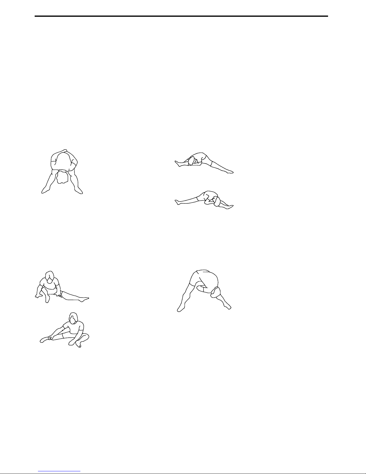
Suggested Stretching Exercises
Lower Body Stretch
Place feet shoulder-width
apart and lean forward. Keep
this position for 30 seconds
using the body as a natural
weight to stretch the backs of
the legs.
DO NOT BOUNCE!
When the pull on the back of
the legs lessen, try a lower
position gradually.
h
Floor Stretch
While sitting on the floor, open
the legs as wide as possible.
Stretch the upper body toward
the knee on the right leg by
using your arms to pull your
chest to your thighs. Hold this
stretch 10 to 30 seconds.
DO NOT BOUNCE!
Do this stretch 10 times.
Repeat the stretch with the left
leg.
Bent Torso Pulls
While sitting on the floor,
have legs apart one leg
straight and one knee bent.
Pull the chest down to touch
the thigh on the leg that is
bent and twist at the waist.
Hold this position at least 10
seconds. Repeat 10 times
on each side.
Bent Over Leg Stretch
Stand with feet shoulder-width
apart and lean forward as
illustrated. Using the arms,
gently pull the upper body
towards the right leg. Let the
head hand down. DO NOT
BOUNCE! Hold the position a
minimum of 10 seconds.
Repeat pulling the upper body
to the left leg. Do this stretch
several times slowly.
Remember always to check with your physician before starting any exercise program.
Cool-Down The purpose of cooling down is to return the body to its normal, or near normal, resting state
at the end of each exercise session. A proper cool-down lowers your heart rate and allows blood to
return to the heart. Your cool-down should include the stretches listed above and should be completed
after each strength-training session.
20
Table of contents
Popular Fitness Equipment manuals by other brands


Pro-Form
Pro-Form Wellness PFICVU26907.0 user manual

Nike
Nike STRENGTH Assembly instructions

DarwinFitness
DarwinFitness RM 50 Assembly and operating instructions

Concept2
Concept2 Dynamic quick start guide

Life Fitness
Life Fitness 95X Cross-Trainer - Inspire Console Operation manual

CARDIOSTRONG
CARDIOSTRONG EX70 Assembly and operating instructions


