7
Installation Guide
Installation Guide
Connect the RED WIRE from the Camera to the REVERSE LIGHT
Reverse wire
from vehicle
vehicle chassis gound
12V+
Permanent Supply
Camera
Red Wire
Not
connected
85 86
30
87
87a
VTC1743M
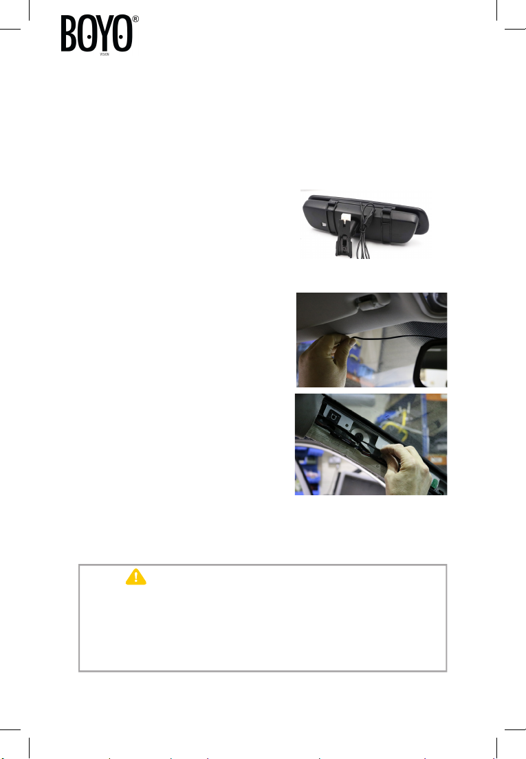
Installing the Camera & Bracket
Once the cable is routed to the rear light you will need to make the
following wiring connections for the camera.
This wire will show 12V+ on a multimeter only when the vehicle is in reverse. Connect
this wire with the supplied blue butt connector.
Connect the BLACK WIRE from the Camera to the VEHICLE CHASSIS
GOUND OR EXISTING GOUND POINT
Connect using the supplied ring terminals.
Connect the YELLOW VIDEO RCA CONNECTOR to the corresponding
YELLOW VIDEO RCA CONNECTOR on the Mirror Monitor Harness.
This should be run down the passenger side of the vehicle to connect up to the
mirror harness previously installed.
Please note:
Many modern vehicles will have a
bulb warning system that can cause
this camera system to function
incorrectly. If this is the case you
will need a 12volt changeover relay
You will need to configure the
wiring as per the drawing
(opposite) to prevent any false
warning or poor operation of this
system.
In some vehicles you will not be
able to find a 12V switched reverse
wire. In this case, you will need to
use a CAN-bus adaptor (available
separately) to generate a reverse
trigger for the camera.
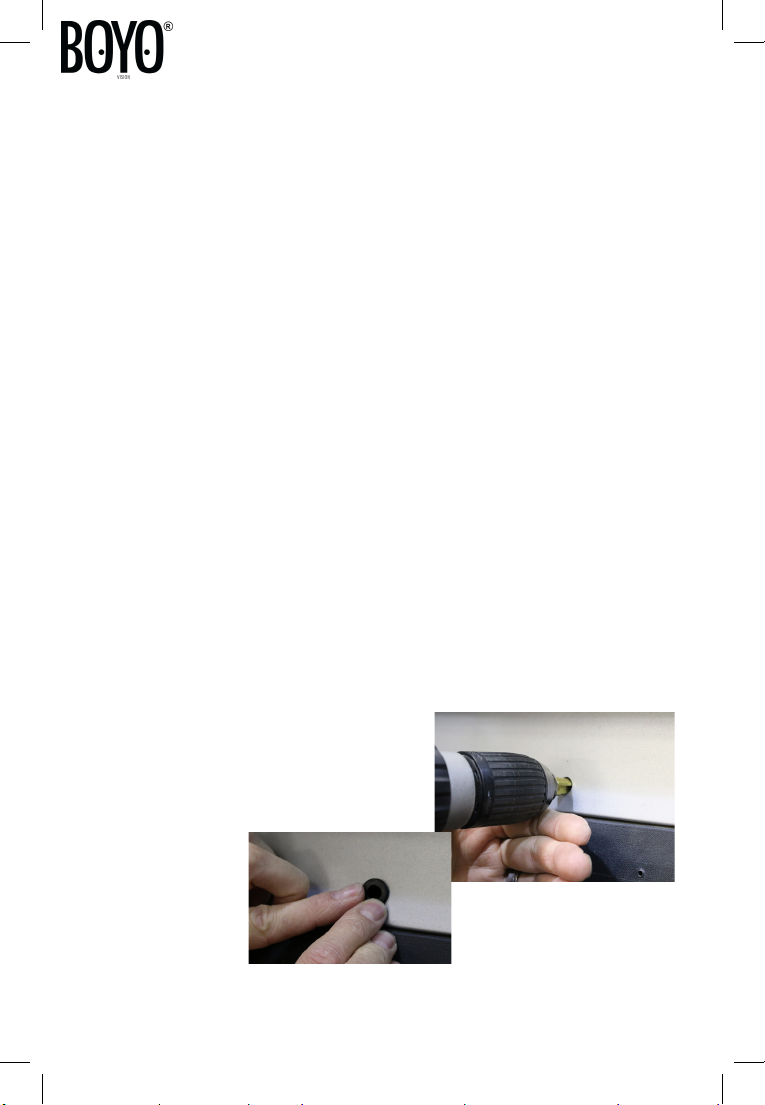
Step 12
Refit the license plate either using
the existing screw holes or with the
3M tape supplied.