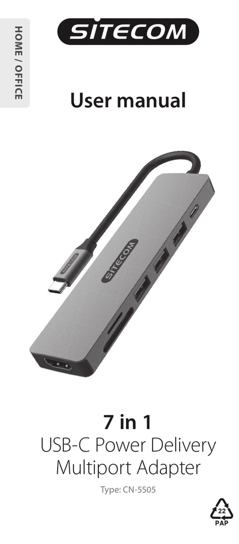
B+B Sensors USB-ADA-12C User manual

OPERATION MANUAL
Technical changes reserved
0141 0316-25 08.02.2021
USB-I²C-adapter
for B+B Temperature-module with I²C-output
DescriptionDescription
Description
Description
In order to support the user for integration of own ASIC module with I²C-
Interface, we have developed this easy to handle PC interface. The probe
can be operated with a PC to test the functionality and capture the measured
values of sensors.
In principle it is an USB on a I²C-converter, which is addressed by a simple
ASCII sequence. The USB-driver software emulates a serial COMinterface.
The ASCII protocol of data communication is well documented. Hence,
integration into own programs through standard communication routines of all
the modern programming languages is possible.
The interface adapter is also suitable for accessing the ASIC, for example, to
program another I²C address.
Further information on ASIC and programming can be obtained on request.
Characteristic features
• Universal USB on I²C Adapter
• For all B+B Temperature modules with I²C-output
• Simple serial ASCII-protocol
• Operation possible over terminal
Areas of application
• Probe testing, product development
• Interface for own PC-based products
• Conguring I²C-Bus address
• Calibration of ASICs
Technical data
PC-USB adapter for I²C
Interface USB-interface, 1.1 and 2.0 compatible
Dimensions (B x H x T)
79 x 21 x 39 mm
Sensor connection Over RJ11/RJ12 plug, 6-pin
Serial communication 19200 Baud, 8N1, ASCII protocol
Voltage source Over USB-interface, 5 V DC
Operating current
max. 80 mA
CC-conformance
EMV-noise emission:
EMV-noise withstanding
2014/30/EU
EN 61000-6-3:2011
EN 61000-6-2:2007
Scope of supply USB-I²C-adapter, consisting of adapter-cable,
USB-adapter, USB-connection cable and software
on Download-Center
Articleno. USB-I2C-KAB
Attention
Please avoid extreme mechanical and inappropriate exposure.
The device/product is not suitable for potential explosive areas and medical-
technical applications.
USB-I2C-KAB adapter consisting of adapter-cable for B+B temperature/
humidity modules, USB-connection cable and software package on
Download-Center
B+B Thermo-Technik GmbH | Heinrich-Hertz-Straße 4 | D-78166 Donaueschingen
1 / 4

OPERATION MANUAL
Technical changes reserved
0141 0316-25 08.02.2021
USB-I²C-adapter
for B+B Temperature-module with I²C-output
Connection layout of plug module
Quick start with ‚TERATERM‘
TERATERM is an universal, efcient terminal program which you can nd in the
installationversion on the Download-Center. Download-Center: https://down-
load.bb-sensors.com/index.php/login → Login Name: bb-shop, Password: BB-
shop#2017. TERATERM is a free ware; you can nd the license requirements
and copyright note in the installation directory.
Connect the sensor module to the USB adapter. If necessary, use the adapter
cable supplied with the adapter.
Now connect the USB adapter to the PC. The installation of the driver should
automatically take place in Windows. If driver les are required, these are
available on the ZIP in the directory „Driver“ for different operating systems.
In rare cases, when the installation of hardware does not work at the rst att-
empt, you can intervene in the control panel. Further hints on this can be found
in the FAQs on the CD. After th hardware is operational, the message „The new
hardware can now be used“ appears on the screen.
Now install the terminal program TERATERM from the enclosed CD and start
the program. Select the interface under „Serial port“ where the device is con-
nected and set the following communication parameters:
Then carry out the following settings under „Terminal settings“:
After this, the system should be operational.
Reading the values
Note: <CR> means “pressing the carriage return key”.
First test the connection with the hardware: For each character sent, the red
LED on the USBAdapter shortly blinks. If the device answers a
telegram, the green LED also blinks. First send the character V <CR>. In res-
ponse, the USB adapter should reply back the version string:
As per the revision status of the software the contents can vary, if needed, but
a response must come.
If you can not establish the connection here, then check the hardware in Win-
dows control panel and also all other settings mentioned before.After the con-
nection to the module is functional, rst you must initialise the adapter:
T11200 <CR>
To start the reading, the operating voltage to the sensor must be switched on:
IRT78004 <CR>
After this command, the LED near the probe connection glows red and it shows
that the operating voltage is present at the measuring probe.The sensor replies
with 8 characters, in the example it is :3F3944C1. These are the rst set of
measured values.
6-pole multi-pin connector
1 VDD Supply voltage 6...12 V
2 GND Ground
3 SDA Serial Data I²C
4SCL Serial Clock I²C
5 VRH/OWI RH Voltage Output/OWI
6 --- Not used
B+B Thermo-Technik GmbH | Heinrich-Hertz-Straße 4 | D-78166 Donaueschingen
2 / 4

OPERATION MANUAL
Technical changes reserved
0141 0316-25 08.02.2021
USB-I²C-adapter
for B+B Temperature-module with I²C-output
Now, in order to fetch further measured values, every time you will have to
enter:
IR_78004 <CR>
Each time the USB-module replies with the current measured values.
Interpretation of values
The left four hex numbers are the rst channel (e.g. humidity or pressure) and
the following four hex numbers are the values of second channel, usually for
the temperature of the module, if used.
Conversion of measured values
The following example refers to the Humidity-Temperature module and the
transmitted string ‚3EEF4499 ‚ in the answer:
The front four digits ‚3EEF‘ are the humidity value, the following digits ‚4499‘
are for the temperature value in hexadecimal format.
Now, rst the Humidity value is converted from HEX to decimal (in example
16111) and then divided by 327,68 as per the data sheet. On
rounding the two post comma places, the humidity value in decimal format
comes out as 49.17 % RH.
The Temperature value is also rst converted into decimal (17561) and then
divided by 256 as per data sheet and 32 is subtracted from the result.
After rounding off the two post comma places, it results in the temperature
value of 36.60 °C.
With the other modules under consideration. One has to proceed in the same
way as per data sheet. For further information, visit our website:
www.bb-sensors.com
Module Channel 1 Channel 2
Humidity module rel. humidity un-calibrated
Feuchte-
Humidity-Temp. module rel. humidity Temperature
PT1000
PT1000 Temp. module
PT1000
Temperature un-calibrated
Thermoelemente
Thermo element
Temp. module Thermovoltage
Temperature
calibration point
Pressure module Pressure un-calibrated
Command overview for examples
The USB-adapter has a very extensive command set. Detailed description is
available on the enclosed CD. The following explanations are only related to
the commands used in the above examples:
‚V‘ Statement of version string
This command responds back with the version string of the controller Firm-
ware.
‚T11200‘ Initialising
Denition of operating voltage and the time delay before the rst communi-
cation. This command must be sent before the rst I²C communication takes
place. The last 3 digits are for the time delay after switching on the operating
voltage and before the rst reading of measured value.
‚IRT78004‘ I²C Read with on-timing
This command switches on the operating voltage, waits for the time delay as
dened in the initialising sequence and then nishes reading over I²C at the
address stated in the ASIC.
The rst two digits (78) are the 7-bit I²C address of the ASIC. The following 3
digits (in example 004) determines the number of digits to be read.
The ASIC always responds to the address 78, however it can also be program-
med at another address, so that it is possible to operate several ASICs at the
same I²C-Bus.
The time delay enables the ASIC to carry out a measurement after feeding the
operating voltage,
before the measured values are read out rst time.
The operating voltage remains switched on even afterwards. Hence, the IRT
command is required only for the rst time to switch on the operating voltage.
‚IR_78004‘ I²C read
This command is identical to the previous one, however without switch on of
the operating voltage and without time delay.
This I²C-read command is used for all further read operations in response.
B+B Thermo-Technik GmbH | Heinrich-Hertz-Straße 4 | D-78166 Donaueschingen
3 / 4

OPERATION MANUAL
Technical changes reserved
0141 0316-25 08.02.2021
USB-I²C-adapter
for B+B Temperature-module with I²C-output
Accessories
Temperature-module Thermocouple, Scope of delivery: Module + Thermocouple type K
Article Article number
Measuring range -270...+300 °C THMOD-I2C-300
Measuring range -270...+800 °C THMOD-I2C-800
Measuring range -270...+1370 °C THMOD-I2C-1370
Temperature-module Pt1000 with voltage output 0...5 V and I²C-bus
Article Article number
Measuring range -32...+95,9961 °C TEMOD-I2C-R1
Measuring range -32...+223,992 °C TEMOD-I2C-R2
Measuring range -32...+479,984 °C TEMOD-I2C-R3
B+B Thermo-Technik GmbH | Heinrich-Hertz-Straße 4 | D-78166 Donaueschingen
4 / 4
Popular Adapter manuals by other brands
Intel
Intel ETHEREXPRESS PRO/100 Quick installation guide and Modem Information Guide
Cal Test Electronics
Cal Test Electronics CT4140A user guide
Renkforce
Renkforce 1516102 operating instructions
Anritsu
Anritsu K220 Series Operation and maintenance manual
TDK-Lambda
TDK-Lambda DTM70 Series instruction manual

3idee
3idee hp-32f Assembly instructions
