manuals.online logo
Brands
  1. Home
  2. •
  3. Brands
  4. •
  5. Honeywell
  6. •
  7. Adapter
  8. •
  9. Honeywell Q7800F Series User manual

Honeywell Q7800F Series User manual

1 65-0093—1
G.R. • 5-93 • ©Honeywell Inc. 1993 • Form Number 65-0146
Fig. 1—Approximate dimensions of Q7800F Adapter Subbase in in. [mm].
Installation
WHEN INSTALLING THIS PRODUCT…
1. Read these instructions carefully. Failure to follow
them could damage the control or cause a hazardous
condition.
2. Check the ratings in the instructions and on the
control to make sure the control is suitable for your
application.
3. Installer must be a trained, experienced Flame
Safeguard service technician.
4. After installation is complete, check out control
operation as provided in these instructions.
12
13
14
15
16
17
18
19
20
21
22
G
L2(N)
3
4
5
6
7
8
9
10
F (11)
5 [127]
5
[127]
1 [44]
3
4
M5648
1
4[6]
Q7800FAdapter Subbase for
Connecting 7800 SERIES
to Q270 Subbase
Application
The Q7800F Adapter Subbase is used for connecting
the 7800 SERIES Relay Module to the Q270 Subbase.
ThisallowsreplacementoftheRA890orR4795Primary
Controls with the 7800 SERIES Burner Control System
without a complete system rewiring.
Specifications
MODEL:Q7800F1004(RA890)andQ7800F1012(R4795)
Adapter Subbase connects to the Q270 Subbase and
allows replacement of the RA890 or R4795 Primary
Controls with the 7800 SERIES Burner Control System
without a complete rewiring of the system.
WEIGHT: 15 oz.
DIMENSIONS: See Fig. 1.
ENCLOSURE: NEMA 1.
APPROVAL BODIES:
UnderwritersLaboratoriesInc.:ComponentRecognized.
Canadian Standards Association: Certified.
2
CAUTION
Disconnect power supply before beginning in-
stallation to prevent electrical shock and equip-
ment damage. More than one disconnect may
be involved.
INSTALLATION
NOTE: For installation dimensions, see Fig. 1. The sub-
base will mount on the existing Q270A Subbase.
1. Disconnect the power supply before beginning the
installation to prevent electrical shock and equipment dam-
age.Morethanonedisconnectmay be involved, depending
on the system being replaced.
2. Loosen the thumbscrew and remove the cover from
the RA890 or R4795.
3. LoosenalltenmountingscrewstoremovetheRA890
or R4795.
4. On the Q7800F Subbase, loosen but do not remove
thefourscrewsin thekeyhole slots.Lifttheblackportion of
the Q7800F Subbase off the four screws.
5. Slide the black portion of the Q7800F Subbase to the
left to expose the five mounting screws on the right-hand
side.
6. Position the Q7800F over the Q270A Subbase, and
align the right-hand screws of the Q7800F with the match-
ing holes in the Q270A (marked 1 through 5).
7. Tighten the five screws on the right-hand side of the
Q7800F to form part of the electrical connection between
the Q270 and the 7800 SERIES control.
8. Slide the black portion of the Q7800F to the right to
expose the five mounting screws on the left-hand side.
9. Tighten the five screws on the left-hand side of the
Q7800F to form part of the electrical connection between
the Q270 and the 7800 SERIES control.
10. Makesurethatalltenmounting screws are tightened.
11. Slide the black portion of the Q7800F Subbase back
over the keyhole screws and tighten the screws to complete
the installation.
12. Install the 7800 SERIES Relay Module.
13. Restore power to the system.
Wiring
No additional wiring is normally required. If the device
being replaced is an RA890F,H, or J, an additional wiring
change is required. In the Q7800F1004, bring L1 power
from the power source to the Q7800F Subbase terminal 3
(Fig. 2). In the Q7800F1012, bring L1 power from the
power source to Q7800F Subbase terminal 5 (Fig. 3). See
the wiring diagrams inside the Q7800F.
Fig. 2—Q7800F1004 internal wiring diagram.
M5647
WIRING DIAGRAM FOR Q7800F1004
(FOR REPLACEMENT OF RA890)
120V, 50/60 Hz
USE COPPER
CONDUCTORS ONLY.
IF DEVICE BEING REPLACED IS RA890F, H, OR J, BRING L1 POWER
FROM POWER SOURCE TO THE Q7800F SUBBASE TERMINAL 3.
GE
L2
3
4
5
6
7
8
9
10
F(11)
12
13
14
15
16
17
18
19
20
21
22
G
F
T
T
6
2
1
3
4
5
1
1
Fig. 3—Q7800F1012 internal wiring diagram.
Home and Building Control Home and Building Control Helping You Control Your World
Honeywell Inc. Honeywell Limited—Honeywell Limitée
1985 Douglas Drive North 740 Ellesmere Road
Golden Valley, MN 55422 Scarborough, Ontario
M1P 2V9
Printed in U.S.A. QUALITY IS KEY
M5646
WIRING DIAGRAM FOR Q7800F1012
(FOR REPLACEMENTOF R4795)
120V, 50/60 Hz
USE COPPER
CONDUCTORS ONLY.
IF DEVICE BEING REPLACED IS R4795, BRING L1 POWER FROM
POWER SOURCE TO THE Q7800F SUBBASE TERMINAL 5.
GE
L2
3
4
5
6
7
8
9
10
F(11)
12
13
14
15
16
17
18
19
20
21
22
G
F
6
7
8
2
1
3
4
5
1
1
Checkout
After installation, perform a complete system checkout.
Follow procedures supplied by the equipment manufac-
turer and instructions furnished with the 7800 SERIES
Relay Module.
This manual suits for next models

2

Other Honeywell Adapter manuals

Honeywell DEX-BLE-1 User manual

Honeywell

Honeywell DEX-BLE-1 User manual

Honeywell UC530 User manual

Honeywell

Honeywell UC530 User manual

Honeywell Limitless WLS Series User manual

Honeywell

Honeywell Limitless WLS Series User manual

Honeywell DC515 P2/BS Series User manual

Honeywell

Honeywell DC515 P2/BS Series User manual

Honeywell OWA 100 OneWireless User manual

Honeywell

Honeywell OWA 100 OneWireless User manual

Honeywell OWA 100 OneWireless User manual

Honeywell

Honeywell OWA 100 OneWireless User manual

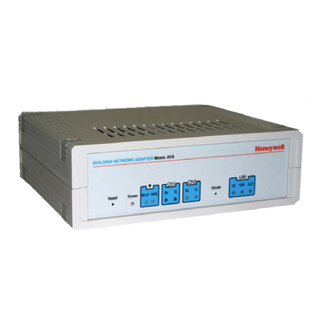
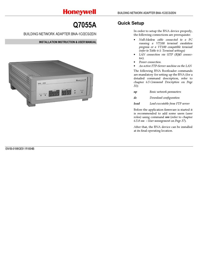
Honeywell Q7055A User manual

Honeywell

Honeywell Q7055A User manual

Honeywell TC-RPFM01 User manual

Honeywell

Honeywell TC-RPFM01 User manual

Honeywell Home C-Wire Adapter User manual

Honeywell

Honeywell Home C-Wire Adapter User manual

Honeywell Q7055A Manual

Honeywell

Honeywell Q7055A Manual

Honeywell Q7055C Series User manual

Honeywell

Honeywell Q7055C Series User manual

Honeywell OWA 100 OneWireless User manual

Honeywell

Honeywell OWA 100 OneWireless User manual

Honeywell DEX-BLE-10 User manual

Honeywell

Honeywell DEX-BLE-10 User manual

Honeywell ComfortPoint Open XFL5 User manual

Honeywell

Honeywell ComfortPoint Open XFL5 User manual

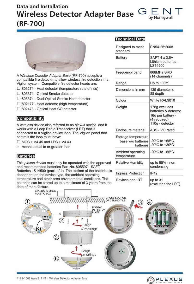
Honeywell GENT RF-700 Instruction manual

Honeywell

Honeywell GENT RF-700 Instruction manual

Honeywell Home C-Wire Adapter User manual

Honeywell

Honeywell Home C-Wire Adapter User manual

Honeywell OneWireless Adapter User manual

Honeywell

Honeywell OneWireless Adapter User manual

Popular Adapter manuals by other brands

Channel Master CM-6000 user guide

Channel Master

Channel Master CM-6000 user guide

Gigafast EE102-DLX user manual

Gigafast

Gigafast EE102-DLX user manual

D-Link AirPro DWL-A650 reference guide

D-Link

D-Link AirPro DWL-A650 reference guide

D-Link DWA-182 Quick installation guide

D-Link

D-Link DWA-182 Quick installation guide

Quatech QSC-100 user manual

Quatech

Quatech QSC-100 user manual

Hamlet HNWU254G Quick installation guide

Hamlet

Hamlet HNWU254G Quick installation guide

Front Runner ECOM195 quick start guide

Front Runner

Front Runner ECOM195 quick start guide

NewerTech Power2U manual

NewerTech

NewerTech Power2U manual

D-Link AirPlus G DWL-G510 Quick installaion guide

D-Link

D-Link AirPlus G DWL-G510 Quick installaion guide

Panasonic BL-PA100KT Brochure & specs

Panasonic

Panasonic BL-PA100KT Brochure & specs

Toa NF-CS1 Read me first

Toa

Toa NF-CS1 Read me first

Nortech CRC220 installation guide

Nortech

Nortech CRC220 installation guide

Bosch CDR 500 Kit Getting Started Guide & Warranty

Bosch

Bosch CDR 500 Kit Getting Started Guide & Warranty

HP FlexFabric 650FLB Quickspecs

HP

HP FlexFabric 650FLB Quickspecs

Sennheiser CEHS-SH 01 quick start guide

Sennheiser

Sennheiser CEHS-SH 01 quick start guide

NETGEAR POE101 Specifications

NETGEAR

NETGEAR POE101 Specifications

GridConnect CAN232 FD user manual

GridConnect

GridConnect CAN232 FD user manual

Siemens BAAP installation instructions

Siemens

Siemens BAAP installation instructions

manuals.online logo
manuals.online logoBrands
  • About & Mission
  • Contact us
  • Privacy Policy
  • Terms and Conditions

Copyright 2025 Manuals.Online. All Rights Reserved.