manuals.online logo
Brands
  1. Home
  2. •
  3. Brands
  4. •
  5. B+K precision
  6. •
  7. Multimeter
  8. •
  9. B+K precision 114B User manual

B+K precision 114B User manual

H(PBECiligffi'I' H(PBECilJ#gd'
lnstruction
Manual
PN:
481400'9-00'l
Printed
inChlna
@2002
8&KPrecision
CorP
22820
Savi
Ranch
ParkwaY
Yorba
Linda,CA92887
USA
TEL:
(714)921-9095
FAx.
(714J9216422
w.DKpreclslon com 1148 Analog
Multimeter
SAFETY ^r wanNthrc
An electricalshock
causing 1
0 mA of current
tc pass
through
theheart
will strtpmosthttnan lrcarlbeats.\/oltageas /owas 35
volts
dc or ac rms
shouldbe considered
dangerottsand hazardotts
since
it canproducaa lethalcurrcntunderceftain conditions.
Highercurrentsare evenrnore
dangerotts.
Observethefollowing
safety precautions:
1. Nevorapplyinput
voltages
ltreater
thanthoselistedin
the
"SPECIFICA-
TIONS"section.
Personalinjury
ordamage
to
thcinstrumentmay
occLlr.
2. Thismeteris
notrecommended
for
high
rroltage
indr-rstrial
rrse;
for
example.
notformeasurements
of440
\1
ACor600
\/ AC industrial
powe!.
mains.
The
unitisintended
forusewith
lowenergyoircttits
to /50 V ACor l0fl0 V DC
or
highenergy
circuits
to250V DCorAC.Accidental
misusebyconnection
acrossa highvoltage,
highenergy
power
sotlrce
whenlhe meterisset
rrp
for
mAmeasurement
maybe
very
hazardous.
3. Turn
equipment
offbeforemaking
rest
connections
inhighvoltage
circuits
Dischargehlgh
voltage
capacitorsaftg!"remDVinq
power.
4. Whenmaking
voltageor
currentmeasurements
inhighvoltageeqtlipment,
nevertouchequipment,
meter,
ortest
leads
urhilepower
isapplied.
5. lf
possible,
familiarize
yotlrselfwith
the
eqLripment
boinqtestedand
ihe
location
ofits
high
voltage
points.
Flowever.
remenlbor
thalhiqh
voliage
mav
appear
atunexpected
points
indefectiveeqrlipmer]l.
6. Be
careful
to
avoid
touchingahiqh
voltage
point.
Remember
tllatacline
volf-
agemav
bepresent
inequipmentunder
test
(for
example,aton-nIf
switch'
fuses,lransformer.
etc.).anytimetheeqllipment
isconnercted
toanacotitlet,
evenifitis
turnedoff.
7. Whenremoving
thecover
forservicingorbattery
replacernent,
removetest
leadsand
makesurethat
theinpLtt
isdisconnected
fromanyhigh
voltage.
8. Use
thetime
proven
"one
hand
in
lhe
pocket"
technique
whilehandlingan
instrument
probe.
Beparticularly
careful
toavoid
contactinga nearbymetal
objectthat
could
provide
a good
ground
return
path.
10,
When
usinga probe,
only
touchtheinsulated
ponion.
Nevertouchthe
exposed
tipponion.
Useaninsula.tedfloormaterial
ora large,insulated
floormatto stand
on,and
aninsulatedworksurfaceon
whichtoplace
equipment;
makecertainsuch
surfacesarenotdamp
or
wet.
Whentestingacpowered
equipment,rememberthat
aclinevoltageisusually
present
onsome
power
input
circuitssuchason-off
swilches,
fuses,
power
transformers,
etc.,anytimetheequipment
isconnectedtoan acout-let.This
istrueevenifthe
eouiomentisturnedoff.
Someequipmentwithatwo-wire
acpower
cord.including
some
witha polar-
ized
powerplug,
isthe
"hot
chassis"type.
Thisincludesmostrecenttele-
vision
receiversandaudio
equipment.A plastic
orwoodencabinetinsulates
thechassis
toprotect
thecustomer.When
thecabinetisremovedforservic-
ing,a serious
shockhazardexistsif
thechassisistouched.Tomake
measurementsin"hot
chassis'equipmenl.
alwaysconnectan isolationtrans-
former
betweentheacoutletand
theequipmentundertest.The
BK PrecisionModelTR-11
0or 1604lsolationTransformer,
orModel1653or
1655AC PowerSupply
issuitableformost
applications.Tobeonthesafe
side,treat
alltwo-wireacpowered
equipmentas"hot
chassis"unless
you
are
sureithasan isolated
oreanh
ground
chassis.
Oninslruments
oranyequipmentwith
athree-wire
acpowerplug,
only
usea
3-wire
outlet.Thisisasafetyfeature
tokeepthehousing
orotherexposed
elementsateanh
ground.
Never
workalone.Someone
shouldbenearby
torenderaidifnecessary.
Training
inCPR
(cardio-pulmonary
resuscitation)first
aidishighly
recommended.
SPECIFICATIONS
Accuracy
specifications
apply
from
+
DC
VOLTS
Ranges:
SensitivitY:
AccuracY:
AC
VOLTS
Ranges:
SensitivitY:
i Accuracy@50/60H2:
: FrequencY
ResPonse:
(t1 dB)
bc
cuRnelt
j
, Ranges:
' Accuracy:
Burden
Voltage
hrstsratce
Ranges:
AccuracY:
Maximum
OPen
Circuit
Voltage:
Maximum
Short
Circuit
Current:
18
"C
to
+28
"C
0-300mV,
3V,
12V'
30
V' '120
V'
300
v, 1200
v
20,000
ohms
Per
volt
t 3olo
offullscale
0-12V,
120V,
300v,
1200v
9,000
ohms
Per
volt
t 4%
of
fullscale
12
V range: 40Hz
to100
kHz
120
V range: 40Hz
to
10kHz
300
Vrange: 40
Hzto
5kHz
1200
V range: 40Hz
to1
kHz
0-50pA,
3mA.
30mA,
300mA,12A
t 3%
of
full
scale
Less
than
600
mV
RX1,
0to
2kohms,
mid
scale
20
ohms
RXl0,
0to
20
kohms,
mid
scale
200
ohms
RX 1k,
0to2 Mohms,
midscale
20
kohms
RX 10k,0to20
Mohms,
midscale
200
kohms
I 3%
of
full
scale
RXl,Xl0,Xlkranges:3V
RX 10k
range:
9
V
RX 1
rangei
150
mA
RX
10
range:
15mA
RXlkrange:150PA
RX 10K
range:
100
UA
11.
12
13
BATTERYTEST
(good- badscale)
Range: 1.5V rangefor batteryteslonly
Load: 7.5ohms
BatteryDrain: 200mA
TRANSISTORLEAKAGETEST
(lceo
scale)
Ranges: 0to
150
pA
onRXlk range
0to
15
mAon
RX 10
range
0to 150mAon RX 1 range
Accuracy: t 5%of scalearc
MaximumAppliedVoltage: 3V,voltagemeasuredon LVscale
TRANSISTOR
GAINMEASUREMENT
Range: 0 to 1,000measured
onhFEscalewilh
range
switchset
toRX 10
dBMEASUREMENT
(dB
scale)
Ranges..
0dB Reference:
Accuracy:
TestLeads:
GENERALSPECIFICATIONS
Movement:
ScaleLength:
Polarity:
PowerSource:
OverloadProtection:
Operating
Temperature:
Dimensions:
(HxWxD).
Weight:
AccessoriesSupplied:
OptionalAccessories:
-10
dB
to
+23
dBon
12VAC
range
+10
dBto43dBon120VACrange
+18
dBto51dBon300
VAC
range
+30
dBon
+63
dBon
1200VACrange
1mWacross600ohms
t 3%of scalearc
Special,supplied
Jeweled
pivots,
50pAfullscale
3-112
inches,mirroredscale
+or-,
polarity
reversalswitch
Batteries:Two 1.5V AAandone9V
250voltceramicfuse.Notforhigh
energy
powpr
measurements
above250volts.
0to+40"C
5-314"x3-718"
x 1-318"
(147
x 99x 35mm)
11oz.(308g)withbatteries
Batteries
Test
leads,1redand1black
Transistortestleads
lnstructionmanual.
Carrying
case,LC-298
CONTROLS
and INDICATORS
Fig. 1 Controls and indlcators
5.
ScaleMirror
Helps
eliminatemeasurementerrors
causedbyparallax
whenviewingscale
Q Scale
Measurement
scale
forresistancereadings.
DCV,A&ACVScale
Measurement
scaleforDCvolts,
DCamperesandACvolts.
BATT.1.5V
Scale
Scaleformeasuring
condition
(good/?/bad)
of 1.5
voltbatteries.
hrr Scale
Scale
formeasuring
transistor
gain.
lceo,
LVandLlScale
Measurement
scale
for
transistorleakage.
dBScale
Measurementscalefordecibels
(dB).
Function/Range
Selector
Rotaryswitch
toselectmeasurementrange
andfunction.
DC+,
DC-(Polarity)
Switch
Polarity
selectorforDCvoltage
andcurrent.
0Q.ADJust
Zeroohms
adjustbeforetakingresistance
measuremenls
(leads
shorted).
11.COM
Jack
Inputforblack,
negative
polarity
(common
orreference)testlead.
12. VQmA
Jack
Inputforred,
positive
polarity,
testlead
formostmeasurementsexcept
12A range.
13. DC12AJack
Red,
positive
polarity
test
leadinputforcurrentmeasurementsup to 12A.
14.
MeterZero
Mechanical
adjustmentto set
pointer
of meter
to exact
zeroposition
when
power isoff. 6
OPERATING
INSTRUGTIONS
A
Awnnltuc
Be suretoreadthoroughty
undersland
and
followthe
practics
given
inthe SAFEW section
ol this
manual
toreducethe riskof
electrical
shock.
GENERAL
CARE
and
OPERATING
TIPS
Mako
surebatteries
arein
good
condition;
seethe
MAINTENANCE
saction
ofthis
manual
forbattery
replacement
instructions
Always
viewthemeter
pointer
sothatits
reflection
inthescalo
minorls
directly
behind
it.This
eliminates
parallax
errors
Whenthe
meter
leads
are
ramovod,
the
pointer
should
beal
exactzerolf
needed.
adjust
the
pointer
to
readzero
bytapping
themeter
face
gently
whlle
adjusting
tha
mechanical
zero
screw.
The
greatest
accuracy
is
achieved
when
readings
areinthe
upper
part
ofthe
meler
scale.Asa
general
rule,
select
thenext
lower
rangewhenrsadlngs
areless
thanhalf
scale.
After
completing
your
measurements,
setthe
Functlon/Range
swltch
to
ACV
and
remove
leads
fromthe
meter.
Never
leavetheFunctlon/Range
switch
intheQ Dosition
toconserve
battery
power.
v.
10. DC
VOLTAGE
MEASUREMENTS
N tout'o*
Nevdr try to measure voltages greater than 120o v. Higher voltages
coulddamage the meter and/or increase the riskof electical shock
Toprevent instrument damage. always setthe Function/Range
selectorto a rango highor than the maximum voltage you expect
to measure. ff the voltage is unknown. staft with the highest range'
Plugblack
testleadinto
the COM jack and redtest lead intothe VQmA jack
Set Polarity selector to DC+ or DC - as determined by polarity of voltago
vou intend
to measure.
1
3 Set Function/Range switchto desiredV: range. lf range is unknown,
select
1200V.
4. Connectblacktest lead
to pointof reference(common),redtest leadto
desiredmeasuring point.
The common should neverexceed 600 V
(DC + AC peak)with respect
to earth ground.
5. Read voltageat related
scale.For best accuracy,
tryto get a readingof al
least 1/3 scaledeflection.
AC VOLTAGE MEASUREMENTS
CAUTION
Never try to measure voltages greater than 12OOV. Higher volt-
ages could damage the meter and/or increase the riskof electrical
shock.
Toprevent instrument damage, always set the Function/Range
selector to a range higher than the maximum voltage you expect
to measure. lf the voltage is unknown, staft with the highest range.
1. Plugblacktest lead intothe COM iack and red test lead intothe VCImA
jack.
2. Set Function/Range switchto desiredV- range. lf range is unkndwn,
select1200V.
3. Connectblacktest lead to pointof reference(common),redtest lead to
desiredmeasuring point.
The common should neverexceed 600 V
(DC + RC peak)with respect
to earth ground.
4. Readvoltage at related
scale.For best results,
tryto get a reading of at
least1/3scaledeflection.
RESISTANCEMEASUREMENTS
CAUTION
Never apply a voltage to the input terminals when the reslslance
function is selected to avoid damage to the meter. Before taking a
resisfance measurement, make sure circuit under test is elect-
rically "cold",power off and any capacitors discharged.
Plug blacktest lead intothe COM jack and red testlead intothe VOmA jack,
Sel FunctionlRange
switch
to desiredohms/resistance
range.
3. Shonleadstogetherfirmlyand verifythat pointer
restson exactzelo ohms
lf needed, adjustthe 0c, ADJ controlto assure poinlerrestson zero Repeal
this check eachtime range is changed. lf pointer
cannot be zeroed,one or
both batteriesmay be weak See the MAINTENANCEsectionof this manual
to check and/orreplacethe batteries.
4. Connect test leadsacrosscomponentor circuit
beingmeasured.Obtain
correctresistancevalue by multiplyingscalereadingby X lactor
(X1/X1o/etc)
of rangeselected For besl accuracy,select a range thatgives
a readingas closeas possible
to the zero end of the scale.
NOTE
, When
makingresistancemeasurements,
beawarethattheopen
circuit
voltage
betweenthe
-COMand
+terminalsishighenough
toforuard-bias
typicalsemiconductors.
Thisvoltageisabout3Vin
theX1,X10,Xl KrangesandaboutI V intheX10Krange.
I OUT-OF-CIRGUITDIODETESTS
i||I fh" resistancefunction
of this metercan be used to checkthe forward/reverse
i resistanceratio
of diodedevices.
This is not a " fool-proof
" test,but it'sreason-
I abtyreliablein mostcasesAlso,see TransistorTests for more semiconductor
' checks.
'l
. Remove diode or similardevice beinqtestedfrom circuit.
2. Selectdesiredresistancerange,typicallyXl K.
*
)1
3. Connecttestleads
acrossdiode,thenreverse
connectionsResistanceratio
shorrld
beat
least
10,000:1.
nearinfinl$in
onedirectionandlowresistance
inother
direction.
.lfmeterreadingis
nearinfinitv
in
both
directions,the
diode
deviceis
probably
open.
.lfmeter
readingisverylow
in
bothdirections,the
diode
devicois
probably
shorted
TRANSISTOR
MEASUREMENTS
This
meter
providos
threetransistor
measurement:leakage.
amplificationfactorand
had/good
condition.Thesemeasurements
aremadewith
the
useoftransistor
test
socl<bi,i6distanco
functionandtrensistor
scalesofthismeterBothNPN
andPNP
transistors
can
be
testsd.
Translstor
hFEtest
1. SqitheFunctlon/Range
selector
toR X 10,
withtwotest
probeplugod
in
COMand
VQmAjack,
shorttheleadsand maks0 ohm adjustment
with0OADJ knob.
2. IfyouaretestinganNPNtransistorinsertthetransistortolowerthreeholesofthe
socket
withblackmarklngNPN.
asthe
fig.2
shown,
and
get
reading
onblus
hre
scale:
lt
readslc/le
=hrr
TranslstorlcEo
test
1
. SetthoFunction/Rango
selectortoaappropriato
O range,
makezeroohnrn
ad.justment,insertthe
CandEleads
tothetransistortestsocket,
asshown
in
Fig,3,
read
the
leakage
current
value
on
Llscale
accordingtotheshortcircuit
currentof
various
resistance
range.
2. Thelceo
couldalsobemeasurcdbyusing
testleadsin-qtead
oftostsockol.Contacl
Black
probe
to
ClaadofNPNtransistor
orE
of
PNPtransistor,
andconneclRed
probe
toE
of
NPI'l
or
CofPNP
transistor,alsoread
lceoonLlscare.
Fig.
2 hretest Fig.3
lceotest
Bad/good
Judgment
.Transislor
bad,open:
Zero
(0)
reading
inbothstates,
withbase
openorclosed.
.Transistor
bad,collector-to-emitter
short:Highreading
inboth
stales,withbase
oDen
orclosed.
Note
Germanium
Transistors
Note:
Theleakagecurrentin
thesetranslstors
always
flows
lothecollector.
This
causesanerror
intheamplification
factorreading.
To
compensate
forthis
error,subtract
thereadingonthe
ICEOscale
fromthereading
onthehFE
scale.
DC
CURRENT
MEASUREMENTS
lNwrnuue
.Always
connect
meterin seieswithloadwhen
measuingcumnt.
lf youincorrectlyconnectit in parallelwiththeload. it providesa low
impedance
path,
almost
a short.shunting
tho
load.This
high
cunent
path
coulddamage
themetor
and/orequipment
under
tost.
.Always
select
arangehigh
enoughto pass
thecunent
youplanto
measure.
lf current
valueisunknown,orindoubt.staftwith
the
+ 1
2Vrange.
Neverexceed
thecurrentrange
selected
orrange
of
therelated
jack.
. Only
usethis
metertomeasure
dccunents:
nevertryto useitto
measure
accurent.
Plug
blacktest
leadinto
the COM
jack.
Plug
restlestlead
intoappropriate
jack
forcurrent
levelthat
you
intend
to
measure.Use
theDC+'l2A
jack
forcurrbntlevels
greater
than
0.3A
(300
mA)butnot
exceeding12
A.
SettheFunctionlRange
switchto
appropriaterange.
Remove
power
from
circuitunder
test.itmust
beelectrically
"cold".
Open
circuit
atapoint
thatdoes
not
exceed
600V (DC
+AC
peak)
from
earth
ground,
orchassis
ofthe
equipmentunder
test.
1'!
,1
q :2
I 13,
4
10
5. Connect
meterinserieswithline
opened;redtestleadtopositive
(+)
side,
blacktestleadto
negative
(-)
sideofthisline.
6 Apply
power
tocircuit
andobtaincurrentvaluebyreadingrelatedscale
al
meter.
Forbestaccuracy,make
surerangeselected
gives
a readingofat
least1/3scaledeflection.
7.Turn
power
offandrestorecircuittoits
originalcondition.
dB MEASUREMENTS
ThedBfunction
of
this
meterisactuallyanacvoltage
measurementscaled
to
read
indB.Zero
dBm,
labeled
as0 dBatthismeter,equals07746V rms
(1
mWinto600ohms).lflhemeasurement
istakenacrossanimpedanceother
than
600ohms,usethefollowing
tabletodeterminethemetercorreclionfactor.
Algebraicallyaddthe
correctionfactor
(in
dB)to
the
meter
reading
(in
dB)for
the
correctvalueindBm.
1. Connect
blacktestleadtoCOM
iackand
redtest
leadto
+iack.0
MAINTENANCE zN
wanrurrue
To avoid personal harm and/or damage to the equipment. remove test
leads before changing batteries, or fuse,or servicina meter.
BATTERY REPLACEMENT
This meterusesthreebatteries:
two .l
.5V"AA,'
batteries
forthe Xi , X10,X1 K
ranges
and one I V bailery
for the Xl
0K range.
The Fig.4
belowsnows
the location
of the batteries
and two prolective
fuses.
Test batteries
when you are near the full
adjustment
limit
of 0e ADJ in any of the
resistance
ranges.
Be sureto replace
low or discharged
batteriesprompfly.
Low batteries
leak
corrosive
acid.
2. Selectthe desked ACV
range.The dB scale is calibrated
for a
directreadingon the 12VAC range.Other
rangescan be used by adding an
appropriatefactor as shown in the following
chart.
3.
Read
valueshownondB
scaleand
addany
compensationfactors
as
determinedby
your
operating
rangeand/or
impedanceifits
value
isnot600
ohms.
ACVRANGE 1) 120 300 120(
ADDdB 020 28 40
ACV/dBRangeCompensation
o20
.E
c ln
a
on
O,rn
o
o -?o
6F22
9V
F0.5A,/250V
Fig.4
Battery
and
fuse
reptacement
-30
F't2N250V
t.)
12
1. Remove
rearcase,
heldbytwo
Phillips
screws
2. Note
polarity
and
arrangement
ofbatteries,
then remove
batteries
and
replace
cover.
3. Plugblack
test
leadintocoM jack,
redtestlead
intoVCImA
jack.
4, Set
Function/Range
to
BATT.
1.5V totest "AA"
batterias
Discard
and
replaceif
pointer
rests
inBADor
?areaofscale.
When
replacing,be sure
toreplaceboth
batteries
ofset.Set
Functioni
RangetoDCV,
12Vto
test9V battery'
Discardand
replaceif
pointer
readslesslhan
I V.
5.Afterseruicing,
replacecoverand
securingscrews.
FUSEREPLACEMENT
Thismeter
is
protected
byaFast
0.5A,/250V
anda 12N250V
5x20mm fuse.
lfthe
meterisinoperative,
thefuse
is
probably
blown.
Toreplace
the
fuse'
removerear
cover
whichisheldby
twoPhillips
screws.
Onlyreplace
fusewiththe
original
type
TESTLEADS
Periodically
examine
thetestleads
loensure
theyarenot
intermittent
orbroken
Also,make
sure
that
good
contact
pressure
exists
between
the
jack
and
recep-
tacles.Keeo
contactareas
cleanand
freefromdirt.
H(PffiCisffFg'
B&KPrecision
Corp.warrants
totheoriginal
purchaser
that
its
product
andlhecomponent
parts
thereof,will
befreefromdefects
inworkmanship
and
materialsfor
aperiod
ofone
year
fromthedate
ofpurchase.
B&KPrecision
Corp.will,
without
charge,repairorreplace,
atits
option,
defeclive
product
orcomponent
parts.
Returned
product
mustb€
accompanied
by
proof
of
the
purchase
date
intheforma sales
receipt.
Toobtainwarranty
coveragein
theU.S.A.,this
product
mustbe
registered
bycompleling
andmailing
theenclosedwarranty
cardto:
B&KPrecision
Cory.,
22820SaviRanch
P'arkwayYorba
Linda,CA92887
withinfifteen
(1
5)days
from
proof
ofpurchase
date.
Exclusions:
Thls
warrantydoes
notapplyinthe
eventof misuse
or abuse
oftheproduct
or asa result
of unauthorized
alternaflons
or repairs.
lt isvold lfthe serialnumber
lsalternated,
defaced
or
removed.
B&KPrecision
Corp.shall
notbeliablefor
anyconsequential
damages,
includingwithout
limitation
damagesresulting
fromloss
ofuse.Some
statesdonol
allowlimitation
ofincidentalorconsequential
damages,
sotheabove
limitation
orexclusionmaynot
applyto
you.
Thiswarranty
gives
you
speciflcrights
and
you
mayhaveotherrights,
whichvary
fromstate{o-state.
ModelNumber DatePurchased:
15
14
H(PffiCiffi'
Service
Information
Warranty
Servlce:
Pleaso
returnthe
product
in
theorlglnal
packeglng
wlthproof
ofpurchese
tothobelowaddressClearly
state
Inwritlng
the
parformanc€
probl6m
and
returnany
l6ads,
connectors
andaccessories
that
you
ara
uslng
wlththedevlce,
Non-Warranty
Servlce:
Raturn
tha
product
Intheorlglnal
packaglng
to
thabelow
addi6s9.
Cloerly
state
Inwrltlng
ih€ perfolmanca
problem
and
return
enyl6ads,
connectors
endaccessorlos
that
you
areuslng
wlththe
devlce.
CuEtomers
noton
opan
accountmust
Includ€
paymont
Inth€
formofamon6y
ord6forcredlt
card.For
themost
cunent
repair
chargeB
contact
thefactory
boforeshipping
theproduct.
Return
allmerchandlse
toB&K
PreclslonCorp
wlth
pre'pald
shlpplng.
Thoflat-rets
repalr
chargeIncludes
relurnshlpping
to
locatlons
lnNorth
Amerlca,For
overnlght
shlpments
andnon-North
America
shlpping
fees
contact
B&KProclslon
CorP..
B&KPreclBlon
Gorp.
2282O
SaviRanchParkway
Yorba
Linda,CA92887
Phone: 714-921-9095
Facsimile:
71
4-521
-6422
Email:
[email protected]
Include
wlththeInstrument
yourcomplete
return
shlpplng
address,
contact
namo,
phone
numberand
descrlptlon
of problem.
22820SaviRanchParkwaY
Yorba
Linda,CA92887
Tel: 714-921
-9095
Fax:714-921-6422
16

Other B+K precision Multimeter manuals

B+K precision 2712 User manual

B+K precision

B+K precision 2712 User manual

B+K precision 2860A User manual

B+K precision

B+K precision 2860A User manual

B+K precision 2703A User manual

B+K precision

B+K precision 2703A User manual

B+K precision 2408 User manual

B+K precision

B+K precision 2408 User manual

B+K precision 2706B User manual

B+K precision

B+K precision 2706B User manual

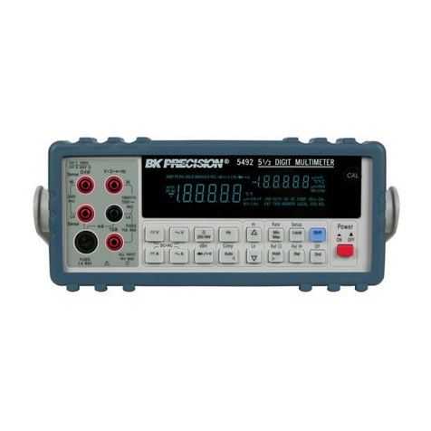
B+K precision 5492 User manual

B+K precision

B+K precision 5492 User manual

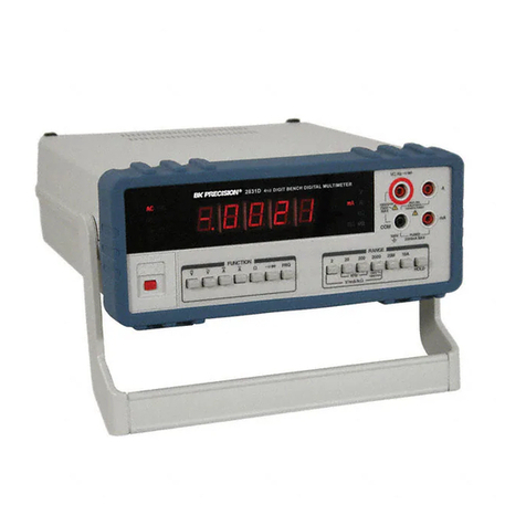
B+K precision 2831D User manual

B+K precision

B+K precision 2831D User manual

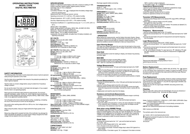
B+K precision 2707B User manual

B+K precision

B+K precision 2707B User manual

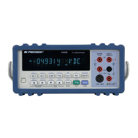
B+K precision 5492B User manual

B+K precision

B+K precision 5492B User manual

B+K precision 5360 User manual

B+K precision

B+K precision 5360 User manual

B+K precision 2831D User manual

B+K precision

B+K precision 2831D User manual

B+K precision 5490C Series User manual

B+K precision

B+K precision 5490C Series User manual

B+K precision 2712 Manual

B+K precision

B+K precision 2712 Manual

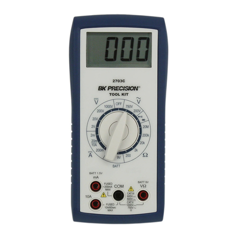
B+K precision 2703C User manual

B+K precision

B+K precision 2703C User manual

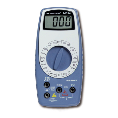
B+K precision 2405A Mini-Pro User manual

B+K precision

B+K precision 2405A Mini-Pro User manual

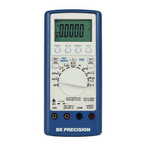
B+K precision 392 User manual

B+K precision

B+K precision 392 User manual

B+K precision 878A User manual

B+K precision

B+K precision 878A User manual

B+K precision 390A User manual

B+K precision

B+K precision 390A User manual

B+K precision 5492B User manual

B+K precision

B+K precision 5492B User manual

B+K precision Survivor 2870 User manual

B+K precision

B+K precision Survivor 2870 User manual

B+K precision 2705B User manual

B+K precision

B+K precision 2705B User manual

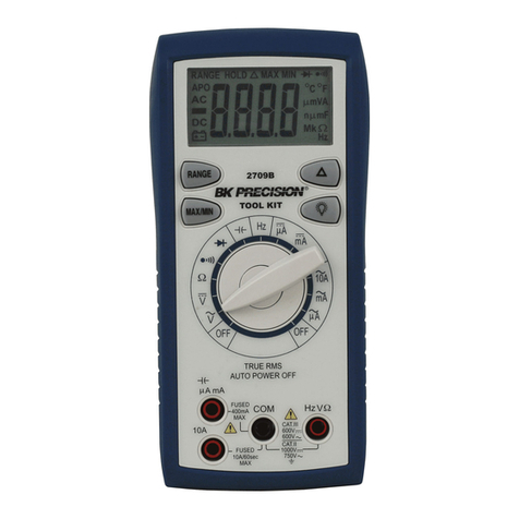
B+K precision 2709B User manual

B+K precision

B+K precision 2709B User manual

B+K precision 390B Series User manual

B+K precision

B+K precision 390B Series User manual

B+K precision 2703B User manual

B+K precision

B+K precision 2703B User manual

Popular Multimeter manuals by other brands

Unit UT-33D+ user manual

Unit

Unit UT-33D+ user manual

Unit UT204A operating manual

Unit

Unit UT204A operating manual

Unit UT71A operating manual

Unit

Unit UT71A operating manual

Unit UT501 operating manual

Unit

Unit UT501 operating manual

Pro's Kit MT-2017 user manual

Pro's Kit

Pro's Kit MT-2017 user manual

Unit UT2000 series operating manual

Unit

Unit UT2000 series operating manual

Unit UT 61+ Series user manual

Unit

Unit UT 61+ Series user manual

Huayi H782 instructions

Huayi

Huayi H782 instructions

HoldPeak 39K Operator's manual

HoldPeak

HoldPeak 39K Operator's manual

Actron SunPro CP7678 operating instructions

Actron

Actron SunPro CP7678 operating instructions

Steinberg Systems SBS-DMB-1000TR user manual

Steinberg Systems

Steinberg Systems SBS-DMB-1000TR user manual

Sanwa PC500 instruction manual

Sanwa

Sanwa PC500 instruction manual

MARTINDALE MM35 Instructions for use

MARTINDALE

MARTINDALE MM35 Instructions for use

Mastech MS8229 Operation manual

Mastech

Mastech MS8229 Operation manual

ELECTRO SYSTEMS DT9205A introduction

ELECTRO SYSTEMS

ELECTRO SYSTEMS DT9205A introduction

GW Instek GDM-8261 quick start guide

GW Instek

GW Instek GDM-8261 quick start guide

Maxwell MX-25 302 user guide

Maxwell

Maxwell MX-25 302 user guide

ZOTEK ZT219 user manual

ZOTEK

ZOTEK ZT219 user manual

manuals.online logo
manuals.online logoBrands
  • About & Mission
  • Contact us
  • Privacy Policy
  • Terms and Conditions

Copyright 2025 Manuals.Online. All Rights Reserved.