manuals.online logo
Brands
  1. Home
  2. •
  3. Brands
  4. •
  5. Maxwell
  6. •
  7. Multimeter
  8. •
  9. Maxwell MX-25 302 User manual

Maxwell MX-25 302 User manual

MX-25 302
User’s guide for 3 1/2 digits multimeter
Description:
1.1 General description
2Display: ½ digits liquid crystal display, with 26 mm characters max. displayable …1999
Polarity: Automatic negative polarity display
Null: Automatic
Measuring method: A/D converter
Measurement rate: 3/seconds
Overload Display: only the “1/-1” symbol is shown
Low Battery : the battery symbol is shown on the display
Security requirements: CE EMC/ LVD. The instrument corresponds to the IEC1010 standard.
Designed to Protection Class II requirement : Double insulation
Operating environment:0°...40 C°, relative humidity :<80%
Storage Temperature: Temperature: -10 C°…+50 C°. relative humidity :<80%
Battery: 9 V, IEC6F22 type battery
Dimensions: 189mm×92,5mm×35mm
Weight: 375g (with battery)
Accessories: Users guide, instrument cable (red and black, 1 pair), Plastic case,K type Thermo sensor,
2
2.1 Electronic characteristics
Punctuality +/- (displayed value’s rate(%) + the number of the digits) 23 +/-5 C°, if the humidity is lower than 75%.
DC Voltage
Measuring range Accuracy Resolution
200 mV 0,1 mV
2 V 1 mV
20 V 10 mV
200 V
+/- (0,5%+3)
100 mV
1000 V +/-(1,0%+5) 1 V
Input Impedance: 10 M
Overload Protection: 200 mV range : 250V DC/AC RMS
2-1000 V range : 1000 V DC/AC RMS
AC Voltage
Measuring range Accuracy Resolution
2 V 1 mV
20 V 10 mV
200 V
+/- (0,8%+5)
100 mV
750 V +/-(1,2%+5) 1 V
Input impedance: 2 V range:10 M
20-700 V range :10M
Overload protection: 1000V DC/AC RMS
Frequency range: 2-200 V range :40-400 Hz
750 V range :40-200 Hz
Shown value : average rate (in case of RMS sinus sign)
3
Resistance
Measuring range Accuracy Resolution
200+/- (0,8%+5) 0,1 
21 
20 10 
200 100 
2 M 
+/- (0,8% + 3)
1 k 
200 M +/-(5,0%(rdg-10) + 20) 100 k 
output voltage : <3V
Overload protection: 250 V DC/AC RMS
DC Current
Measuring range Accuracy Resolution
20 mA +/- (0,8% + 3d) 10 uA
200 mA +/- (1,2% + 4d) 100 uA
20 A +/- (2,0% + 5d) 10 mA
Max : 200 mV
Max input current: 20A (maximum 10 seconds)
Overload protection: 0,2 A/250 V “F” fusion
20A measuring range not ensured!
4
AC current
Measuring range Accuracy Resolution
20 mA +/- (1,0% +5) 10 uA
200 mA +/- (2,0% +5) 100 uA
20 A +/- (3,0% +10) 10 mA
Max. max measuring voltage:200 mV
Max input current: 20 A (max: 10 seconds)
Overload protection: 0,2 A/250 V “F”fusion
20 A measuring range not ensured!
Frequency range :40-200 Hz
Displayed value: general value (in case of RMS sinus signal)
Capacity
Measuring range Accuracy Resolution
20 nF 10 pF
20 uF 1 nF
200 uF
+/- (2,5% + 20)
100 nF
Measuring frequency: 150 Hz
Overload protection: 36 V DC/AC RMS
5
Temperature
Measuring range Accuracy Resolution
+/- (1,0%+3) < 400 C°-40 C° – 1000 C°
+/- (1,5%+15) > 400 C°
1 C°
With K type temperature sensor
Diode Test
Function Description Test mode
Open circuit voltage measurement Open circuit DC current approx. : 1mA
Close circuit DC voltage 3V
A Sound indicates, if resistance between the
V/Ohm and the COM is lower than 70
Output voltage 3 V
Overload protection: 250 V DC/AC RMS
Warning: Don’t connect other power sources to the inputs !
Frequancy
Measuring range Accuracy Resolution
2 kHz 1 Hz
200 kHz
+/- (3,0%+15) 100 Hz
Input sensibility: 1V RMS
Overload Protection: 250 V DC/AC RMS (maximum for 15 seconds)
6
Transistor hfe” test
Function Description Test mode
hfe … the transistors electric power (0-1000)
(All the types)
Basis current around 10 uA
V ce around 3V
2. Use of the device
1. Check the 9 V battery, turn Power On position. If the battery exhausted, the symbol appears on the display.
2. The signs next to the wires are showing, that the input voltage or current shouldn’t be higher than the correct value. In this way you can
protect the internal circuits from the damages.
3. Please, turn the Function switch in to the right position(function).
4. If you don’t know the range of the measuring value, choose the largest range and do it backwards till you find the right one.
2.1 DC and AC voltage measurement
1. Connect the black wire to the “COM”, and the red wire to the “V//Hz plug.
2. Turn the Function switch in to the right V position and connect the wires parallel with the voltage source for the measuring time.
2.1.1 Phase searching function
1. Turn the Function switch to the “TEST” position, connect the red wire to the “V//Hz” socket. A sound and a(flash)light will indicate if
there is phase.
Note:
a. If you don’t know the measured current range, turn the Function button in to choose the largest range and do it backwards till you find
the right one by switching it down .If the “1” or the “-1” appear on the display, that means overload. In this case turn the Function
switch into a higher measure range.
b. Don’t connect higher then DC1000V/AC7000V RMS voltage to the input .
c. Don’t touch the high voltage current during the measure.
7
2.2 Measure of DC and AC current
1. connect the black wire in to the “COM”, the red in to the “mA” (max . 200mA) or the “20A” wire for measuring 200mA – 20A.
2. Switch the Function button in to the right measure range.
3. Connect the wires tightly to the (DC/AC) source for the measure.
4. Between the measuring range of 200 mA and 10A ( current) connect the red wire to the “20A” to measure it.
Note:
a. If you don’t know the measured current range, turn the button to choose the largest range and do it backwards till you find the right
one by switching down .
b. If the “1” or the “-1” appear on the display, that means overload. In this case turn the Function button into a higher measure range.
c. The max. input current is 200mA or 20A depends on the chosen input( the max. time for the test is 15 sec). If the current is higher, it
can blow out the fusion. The 20A measure range is not ensured.
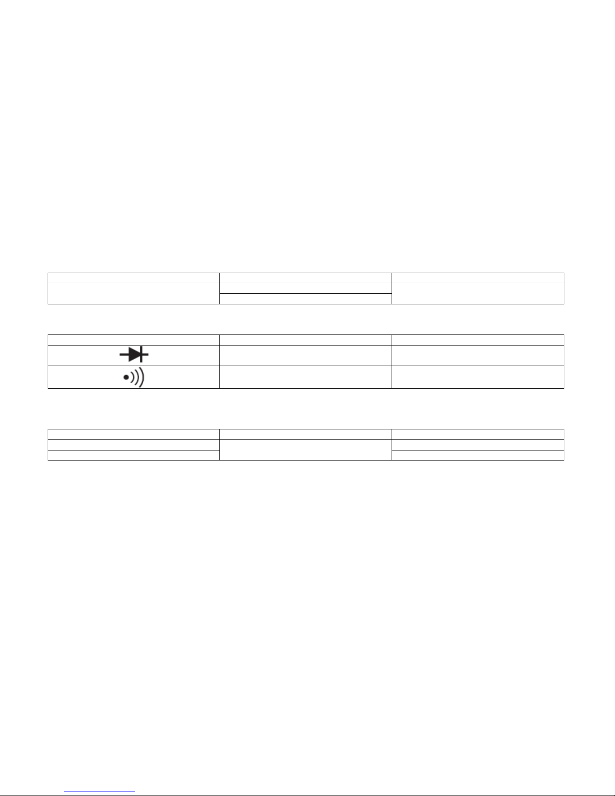
2.3 Resistance measure
1. Connect the black wire to the “COM”, and the red wire to the “V//Hz/C”port.
2. Switch the Function button to the desired resistance’s measure range.
3. Connect the wires parallel with the measurable circuit.
Warning: make sure all the power of the circuit to be measured is off.
Note:
a. If the value of the measurable resistance over helming the value of the maximum measurable level, and if the instrument overloaded, (“-
1” or”1”) choose a higher measure range. Over 1Mresistances the instrument is stabilising the value of the resistor in a few seconds.
This is absolutely normal in high value resistance measures.
b. If you don’t connect resistance to the input (for ex. the circuit is splited ), the “1” or “-1” will appear because the over helming of the
measure limit.
If you are examining a resistance in a circuit, be sure that the circuit has all power removed and all capacitor are fully discharged. Don’t
c. Don’t connect to the instrument any input voltage , because it can damage the integrated circuits.
8
2.4 Capacity measure
1. Set the function switch to the F position.
2. Connect the black test lead to the (-) jack „COM” and red lead to the (+) jack „mA”.
3. Connect test leads across the capacitor under measurement and be sure that the polarity of connection is observed.
Note:
1. If the value of the measurable resistance over helming the value of the maximum measurable level, and if the instrument overloaded, (“-
1” or”1”) choose a higher measure range.
2. Unit: 1uF=103nF 1nF=103pF
3. When checking in-circuit capacitance, be sure that the circuit has all power removed and all capacitor are fully discharged(the electrolite
capacitor shuold be discharged several times).
2.5 Diode and continuity check
1. Connect the black test lead to the COM and the red one to the V//Hz/C port (Note: the polarity of the red wire is +)
2. Turn the Function switch to mode.
3. Connect the leads to the outlet of the diode. Now you can see the open voltage of the diode on the display.
4. Touch two point of the circuit with the wires, a buzzer sounds when the resistance of the circuit to be measured is less than approx.70 Ω.
Note:
1. If you don’t connect any unit to the ports the display will show “1” or “-1”
2. The current flowing through the diode during the test is 1 mA.
3. The display will show the open voltage in mV or “overload” if you switched the polarities.
2.6 Measuring Temperature
1. Set the Function switch to °C or to °F.
2. Put the sensor of the probe into the socket (pay attention to the polarity, it should be -) and put the other to the place of which the
temperature you want to measure. On the display you will see the measured temperature in °C or °F.
9
Note:
1. This unit uses a special temperature measuring sensor.
2.7 Transistor hfe Test
Turn the switch to hfe.
1. Connect the sensor to the COM and mA ports.
2. Put the transistor into the appropriate socket, depending on the transistor being NPN or PNP.
3. The display shows the current amplifying factor of the transistor IB= 10uA, VCE =3V.
2.8 Frequency measurement
1. Connect the instrument cable or shielded wire to the COM and to the V//Hz/C port.
2. Set the switch to “200kHz” and touch the source of the signal with the leads.
Note:
1. Do not try to measure the frequency when the voltage is more than 250V (RMS)
2. In noisy environment use shielded cable when measuring low signals
3. Do not touch the circuit when measuring high voltage
2.9 Freezing the display
1. Press the HOLD button to freeze the display with the current data, press the hold again to turn it back to measurement mode.
3. Automatic stand-by mode
1. 15 minutes after the latest measurement the unit will switch to stand-by mode
2. To turn it on again press the POWER button
10
4. Warning
1. When measuring 32 V DC / 25 V AC be sure that no cables are connected to the current measuring socket and the main switch is not in
diode or resistor testing mode.Always make sure that you connected the cable to the right socket for its voltage.
2. Be cautious when measuring voltage higher than 50V, especially in the case of high current.
3. Do not connect the unit to “live” circuits.
4. When measuring current, turn off the voltage before you connect the multimeter. Do not try to measure current that is higher than 20A.
5. When testing the diode or the resistor, turn off the voltage before you start the test.
6. Always select the function and measuring range appropriate for the task. If you are unsure choose the largest range and do it backwards
till you find the right one.
7. Make sure that the instrument wire and the insulation is intact.
8. Be cautious, do not exceed the overload range found in this manual.
9. When switching a fuse replace it with ratings specified.
10. When switching the fuse or changing the battery turn off the multimeter and disconnect every circuit before opening the case of the
device
5. maintenance of the multiemter
1. Keep the multimeter dry, if it gets wet switch it off and dry it immediately. Liquids could corrode the circuits inside the unit.
2. Use the multimeter only in normal temperature, if the temperature gets too high it could shorten the lifetime of the device and can damage
batteries and melt plastic parts.
3. Be careful with the unit. If you drop it, it can damage the multimeter and the case which can cause malfunction.
4. Keep the device away from dust, it can significantly shorten the lifetime of the multimeter.
5. You can clean the unit with a clean wet towel, do not use any cleaning liquids or acids.
11
12
4.2 Servicing the device
1. Changing the battery (one 9V battery is required)
a. Switch off the unit and disconnect every external circuit. Disconnect the instrument cable from the socket.
b. Remove the screws then the cover on the bottom side.
c. Remove the flat battery and insert a new one from of same type ( Standard 9V battery).
2. Switching a fuse (5x20 mm ,200 mA / 250 V “F” labeled fused are used)
a. Switch off the unit and disconnect every external circuit. Disconnect the instrument cable from the socket.
b. Remove the screws then the cover on the bottom side.
c. Replace the melted fuse with a new one from the same level and type .

Other Maxwell Multimeter manuals

Maxwell 25107 User manual

Maxwell

Maxwell 25107 User manual

Maxwell 25521 User manual

Maxwell

Maxwell 25521 User manual

Maxwell 25301 User manual

Maxwell

Maxwell 25301 User manual

Maxwell 25303 User manual

Maxwell

Maxwell 25303 User manual

Maxwell 25401 User manual

Maxwell

Maxwell 25401 User manual

Maxwell 25201 User manual

Maxwell

Maxwell 25201 User manual

Maxwell MX-25 401 User manual

Maxwell

Maxwell MX-25 401 User manual

Maxwell 25303 User manual

Maxwell

Maxwell 25303 User manual

Maxwell 25201 User manual

Maxwell

Maxwell 25201 User manual

Maxwell 25304 User manual

Maxwell

Maxwell 25304 User manual

Maxwell 25301 User manual

Maxwell

Maxwell 25301 User manual

Maxwell 25700 User manual

Maxwell

Maxwell 25700 User manual

Maxwell 25201 User manual

Maxwell

Maxwell 25201 User manual

Maxwell 25304 User manual

Maxwell

Maxwell 25304 User manual

Popular Multimeter manuals by other brands

Duratool D03046 Operator's instruction manual

Duratool

Duratool D03046 Operator's instruction manual

Maxwell Digital Multimeters 25331 user manual

Maxwell Digital Multimeters

Maxwell Digital Multimeters 25331 user manual

Mastech MS8302F manual

Mastech

Mastech MS8302F manual

Fluke 8062A instruction manual

Fluke

Fluke 8062A instruction manual

Keithley 165 instruction manual

Keithley

Keithley 165 instruction manual

Rain Bird TI-DSA500 operating instructions

Rain Bird

Rain Bird TI-DSA500 operating instructions

RCS MS8216 owner's manual

RCS

RCS MS8216 owner's manual

Velleman DVM4 00 Series user manual

Velleman

Velleman DVM4 00 Series user manual

Simpson Electric 303 Operator's manual

Simpson Electric

Simpson Electric 303 Operator's manual

GB GDT-311 owner's manual

GB

GB GDT-311 owner's manual

Fluke 114 user manual

Fluke

Fluke 114 user manual

Metrix MX 21 user manual

Metrix

Metrix MX 21 user manual

Pro's Kit MT-7602 user guide

Pro's Kit

Pro's Kit MT-7602 user guide

B+K precision 389A Test Bench instruction manual

B+K precision

B+K precision 389A Test Bench instruction manual

Unit UT30B operating manual

Unit

Unit UT30B operating manual

Axio MET AX-102 Operation manual

Axio MET

Axio MET AX-102 Operation manual

Unit UT60H operating manual

Unit

Unit UT60H operating manual

Dilog DL9308 operating manual

Dilog

Dilog DL9308 operating manual

manuals.online logo
manuals.online logoBrands
  • About & Mission
  • Contact us
  • Privacy Policy
  • Terms and Conditions

Copyright 2025 Manuals.Online. All Rights Reserved.