manuals.online logo
Brands
  1. Home
  2. •
  3. Brands
  4. •
  5. Bpt
  6. •
  7. Stereo System
  8. •
  9. Bpt XC/220 User manual

Bpt XC/220 User manual

1
IISTRUZIONI PER
L’INSTALLAZIONE
AVVERTENZE PER L’INSTALLATORE
Queste istruzioni devono essere allegate al deri-
vato interno.
MODULO CITOFONO A VIVA-VOCE XC/220
Citofono a viva-voce da utilizzare negli impianti
citofonici serie 200.
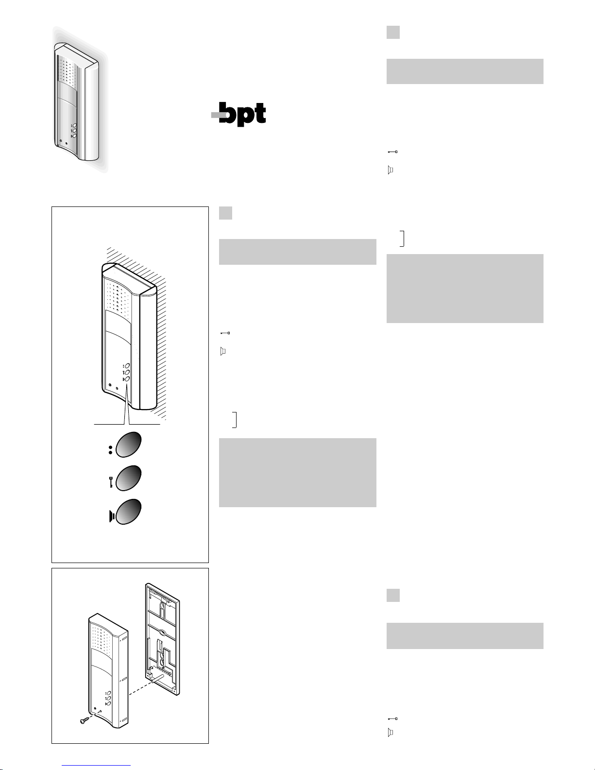
È munito dei seguenti comandi (fig. 1):
•Servizi ausiliari
•
Apriporta
Audio (il pulsante deve essere mantenuto
premuto durante tutta la conversazione)
Funzione dei morsetti
5– alimentazione (comune)
7chiamata
8audio al derivato interno
9audio al posto esterno
• pulsante per servizi
• ausiliari (24 V 50 mA max)
AVVERTENZE PER L’UTENTE
- Non aprire o manomettere l’apparecchio.
- L’apparecchio funziona a bassissima tensione di
sicurezza (24Vca): non deve essere collegato a ten-
sioni superiori.
- In caso di guasto, modifica o intervento sugli appa-
recchi dell’impianto (alimentatore, ecc.) avvalersi di
personale specializzato.
Funzione del ponticello SW1
Normalmente viene fornito inserito. Togliere il ponti-
cello qualora si voglia attenuare il volume della nota
di chiamata (fig. 4).
Caratteristiche tecniche
• Potenza massima commutabile del pulsante ser-
vizi ausiliari: max. 24V 50 mA.
• Temperatura di funzionamento: da 0 °C a +35 °C.
NOTA. Nello stesso impianto non si possono instal-
lare apparecchi a cornetta (C/200 o XC/200) assie-
me ad apparecchi a viva-voce XC/220.
Se si utilizza la centralina di controllo GVV/200 può
funzionare assieme a derivati NC/220.
Installazione del modulo citofono XC/220
Dopo aver tolto il mobile (vite frontale di fig. 2, in
basso), fissare la base direttamente al muro (fig.
3A), oppure alla scatola incasso (fig. 3B o 3C).
Su pareti non perfettamente piane evitare il serrag-
gio eccessivo delle viti.
Effettuare i collegamenti e montare il mobile del
modulo citofono (fig. 4).
Applicare i due fianchi (fig. 5 e 6).
XC/220
01.2001/2405-3800
BPT S.p.A.
30020 Cinto Caomaggiore
Venezia/Italy
1
2
WARNING FOR THE INSTALLER
These instructions should be attached to the
handset.
XC/220 HANDS-FREE MODULE
Hands-free audio module for use in series 200
audio entry installations.
It features the following controls (fig. 1):
•Auxiliary services
•
Door-lock release
Audio (the button must be kept pressed for
the entire duration of the conversation)
Function of each terminal
5– power supply (common)
7call
8audio to receiver
9audio to entry panel
• button for auxiliary
• services (24V 50 mA max.)
WARNINGS FOR THE USER
- Please do not open or tamper the device.
- The device is operating with a very low voltage
(24V AC) and cannot be connected to higher volta-
ges.
- In the case of breakdown or modification of the
apparatus of the system (such as power supplier…)
please contact a specialized maintenance service.
Function of jumper SW1
Normally supplied ready inserted. Remove the jum-
per in the event the volume of the call note is to be
attenuated (fig. 4).
Technical features
• Maximum switching power of the auxiliary servi-
ces button: max. 24V 50 mA.
• Working temperature range: from 0 °C to +35 °C.
NOTE. Handsets (C/200 or XC/200) cannot be
installed together with XC/220 hands-free modules
in the same installation.
When using the GVV/200 control unit, the module
can work together with NC/220 receivers.
Installing the XC/220 receiver module
Having removed the casing (front screw in fig. 2,
bottom), fasten the housing directly to the wall (fig.
3A) or to the embedding box (fig. 3B or 3C).
If walls are not perfectly flat, take care not to overti-
ghten screws.
Wire the receiver module and refit its casing (fig. 4).
Apply the two sides (fig. 5 and 6).
GB INSTALLATION
INSTRUCTIONS
DINSTALLATIONS-
ANLEITUNG
ACHTUNG! NUR FÜR INSTALLATEUR
Diese Anleitungen müßen jede der Sprechgar-
nitur begleiten.
MODUL MIT FREISPRECHFUNKTION XC/220
Der Audiomodul mit Freisprechfunktion ist in den
Haussprechanlagen Serie 200 zu verwenden.
Ist mit den folgenden Steuerfunktionen ausgestattet
(Abb. 1):
•Zusatzdienste
•Türöffner
Audio (Taste während des Gesprächs
gedrückt halten)
2
Funktion der Klemmleisten
5– Stromversorgung (gemeinsam)
7Anruf
8Audio zur Sprechgarnitur
9Audio zur Außenstation
• Taste für Zusatzsteuerung
• (max. 24V 50 mA)
HINWEISE FÜR DEN NUTZER
- Bitte Geräte nicht öffnen oder aufbrechen.
- Das Gerät funktioniert bei niedrigster
Sicherheitsspannung (24V Wechselstrom) bitte
keine höhere Spannung anschliessen.
- Bei Störungen, Änderungen oder Reparaturen
an den Geräten (Netzgerät, usw.) nur an
Spezialisten wenden.
Belegung der Überbrückungsklemme SW1
Wird gewöhnlich schon eingefügt geliefert. Falls
man die Lautstärke des Ruftons herabsetzen
möchte ist die Überbrückungsklemme abzuneh-
men (Abb. 4).
Technische Daten
• Maximale Umschaltleistung der Taste für
Zusatzdienste: max. 24V 50 mA.
• Betriebstemperatur: von 0 °C bis +35 °C.
ANMERKUNG. Die Installation von Geräten mit
Hörer (C/200 oder XC/200) ist in derselben Anlage
mit Geräten mit Freisprechfunktion XC/220 nicht
möglich.
Bei der Verwendung des Steuergehäuses
GVV/200, ist ein Betrieb mit den Sprechstellen
NC/220 möglich.
Einbau des Sprechmoduls XC/220
Gehäuse (Vorderschraube der Abb. 2, unten)
abnehmen, Basis direkt an der Wand (Abb. 3A)
oder am UP-Kasten (Abb. 3B oder 3C) befestigen.
Bei ungeraden Wänden ist ein zu starkes Anziehen
der Schrauben zu vermeiden.
Anschlüsse vornehmen und Sprechmodul-
Gehäuse montieren (Abb. 4). Seitenteile anbringen
(Abb. 5 und 6).
FINSTRUCTIONS
POUR L’INSTALLATION
PRECAUTIONS POUR L’INSTALLATEUR
Cettes instructions doivent accompagner cha-
que poste intérieur.
MODULE VIVE-VOIX XC/220
Module audio à vive-voix à utiliser dans des instal-
lations de portier électronique série 200.
Il est muni des fonctions suivantes (fig.1):
•Services auxiliaires
•Minuterie
Audio (le bouton doit être maintenu enfoncé
pendant toute la durée de la conversation)
Fonction des bornes
5– alimentation (commun)
7appel
8audio au poste intérieur
9audio au poste extérieur
• bouton-poussoir pour services
• auxiliaires (24V 50 mA maxi)
PRECAUTIONS POUR L’USAGER
- Ne pas ouvrir l’appareil.
- L’appareil fonctionne en basse tension de sécurité
(24Vca): il ne doit pas être raccordé à une tension
supérieure.
- En cas de défaut, de modification ou d’interven-
tion sur les appareils de l’installation (alimentation,
etc.), s’adresser exclusivement au personnel spé-
cialisé.
2
3
SW1
1
4
ADVERTENCIA AL INSTALADOR
Estas instrucciones se deben anexar al deriva-
do interno.
MÓDULO MANOS LIBRES XC/220
Módulo audio manos libres a utilizar en las instala-
ciones de portero electrónico serie 200.
Dispone de los siguientes comandos (fig. 1):
•Servicios auxiliares
•
Abrepuerta
Audio (el pulsador debe ser mantenido apre-
tado durante toda la conversación)
Función de los bornes
5– alimentación (común)
7llamada
8audio desde el derivado interno
9audio hacia la placa externa
• pulsador para servicios
• auxiliares (24V 50 mA máx.)
ADVERTENCIAS PARA EL USUARIO
- No abrir ni manipular el aparato.
- El aparato funciona con tensión de seguridad
(24Vca) no debe ser conectado a tensiones supe-
riores.
- En caso de avería o necesidad de modificación o
intervención sobre los aparatos de la instalación
(alimentador, etc.) dirigirse al personal especializa-
do.
Función del puente SW1
Normalmente es entregado conectado.
Quitar el puente en el caso de que se desee ate-
nuar el volumen de la nota de llamada (fig. 4).
Características técnicas
• Potencia máxima conmutable del pulsador servi-
cios auxiliares: máx. 24V 50 mA
• Temperatura de funcionamiento: entre 0 °C y
+35 °C.
NOTA. En la misma instalación no se pueden insta-
lar aparatos con teléfono (C/200 o XC/200) junto con
aparatos manos libres XC/220.
Si se utiliza la centralita de control GVV/220 puede
funcionar con derivados NC/220.
Instalación del módulo manos libres XC/220
Tras haber quitado el envoltorio (tornillo frontal de
EINSTRUCCIONES
PARA LA INSTALACION
Fonction du pontet SW1
Normalement il est fourni inseré. Déplacer le pon-
tet si vous désirez atténuer le volume de la note
d’appel (fig. 4).
Caractéristiques techniques
• Puissance maximale commutable du bouton ser-
vices auxiliaires: 24V 50 mA maxi.
• Température de fonctionnement: de 0 °C à +35 °C.
NOTA. Il n’est pas possible d’utiliser ensemble des
combinés (C/200 ou XC/200) et des appareils à
vive-voix XC/220 dans une même installation.
En cas d’utilisation de la centrale de contrôle
GVV/200, il peut fonctionner avec les appareils à
vive-voix NC/220.
Installation du module vive-voix XC/220
Après avoir enlevé le meuble (vis frontale de la fig.
2, en bas), fixer la base directement au mur (fig.
3A) ou au boîtier à encastrement (fig. 3B ou 3C).
Si le mur n’est pas parfaitement plat, éviter de ser-
rer excessivement les vis.
Effectuer les raccordements et monter le meuble
du module vive-voix (fig. 4). Appliquer les deux
côtés (fig. 5 et 6).
A
83,5 mm
B
60 mm
C3
3
1
2
5
6
la fig. 2, abajo), fijar la base directamente en la
pared (fig. 3A) o bien en la caja empotrada (fig. 3B
ó 3C).
En paredes no perfectamente planas cabe evitar
un apriete excesivo de los tornillos.
Efectuar las conexiones y montar el envoltorio del
módulo manos libres (fig. 4). Aplicar los dos lados
(figs. 5 y 6).
PINSTRUÇÕES
PARA A INSTALAÇÃO
AVISO PARA O INSTALADOR
Estas instruções devem acompanhar cada deri-
vado interno.
MODULO VIVA-VOZ XC/220
Módulo áudio com viva-voz para utilizar nas insta-
lações de telefones porteiros série 200.
Está munido dos seguintes comandos (fig. 1):
•Serviços auxiliares
•Abertura da porta
Áudio (o botão deve ser mentido pressiona-
do durante toda a conversação)
Função dos bornes
5– alimentação (comum)
7chamada
8áudio ao derivado interno
9áudio à placa botoneira
• botão para serviços
• auxiliares (24V 50 mA máx.)
PRECAUÇÕES PARA O UTENTE
-Não abrir os aparelhos.
- O aparelho funciona a baixa tensão de segurança
(24 Vca) e não deve ser ligada a tensão superior.
- Em caso de avaria, necessidade de modificação
ou intervenção nos aparelhos (alimentador, etc. ),
dirigir-se ao pessoal especializado.
Função da ponte SW1
Normalmente é fornecida inserida. Tirar a ponte se
por acaso se deseja atenuar o volume do toque de
chamada (fig. 4).
Características técnicas
• Potência máxima comutável do botão de ser-
viços auxiliares: máx 24V 50 mA.
• Temperatura de funcionamento: desde 0 °C até
+35 °C.
NOTA. Na mesma instalação não se podem insta-
lar aparelhos com auscultador (C/200 ou XC/200)
juntamente com aparelhos a viva-voz XC/220.
Se vocês utilizarem a central de controlo GVV/200
pode funcionar juntamente com derivados NC/220.
Instalação do módulo a viva-voz XC/220
Depois de ter tirado o móvel (parafuso frontal da
fig. 2, em baixo), fixar a base directamente ao
muro (fig. 3A), ou então com caixa de encastre (fig.
3B ou 3C).
Sobre paredes não perfeitamente faceadas, evitar
o aperto excessivo dos parafusos.
Efectuar as ligações e montar o móvel do módulo
a viva-voz (fig. 4). Aplicar as duas partes laterais
(fig. 5 e 6).
4

Popular Stereo System manuals by other brands

Nikkei NMD370 user manual

Nikkei

Nikkei NMD370 user manual

Panasonic SH-FX80 operating instructions

Panasonic

Panasonic SH-FX80 operating instructions

Sony RDP-XF300iPN operating instructions

Sony

Sony RDP-XF300iPN operating instructions

Sharp CD-SW300H Operation manual

Sharp

Sharp CD-SW300H Operation manual

Panasonic SC-PM500 operating instructions

Panasonic

Panasonic SC-PM500 operating instructions

Kenwood HM-382MD instruction manual

Kenwood

Kenwood HM-382MD instruction manual

Samsung MM-ZB9 instruction manual

Samsung

Samsung MM-ZB9 instruction manual

Sony ZS-BTG905 operating instructions

Sony

Sony ZS-BTG905 operating instructions

Philips DCD8000/12 user manual

Philips

Philips DCD8000/12 user manual

JVC MX-J555V instructions

JVC

JVC MX-J555V instructions

Sony HCD-MD5 Service manual

Sony

Sony HCD-MD5 Service manual

Samsung MAX-DB630 instruction manual

Samsung

Samsung MAX-DB630 instruction manual

LEGRAND AU7008 Series user guide

LEGRAND

LEGRAND AU7008 Series user guide

Sharp CD-BP1200W Service manual

Sharp

Sharp CD-BP1200W Service manual

Korg GEC3 user manual

Korg

Korg GEC3 user manual

Sylvania SKCR2826BT instruction manual

Sylvania

Sylvania SKCR2826BT instruction manual

Kenwood M-718BT operating manual

Kenwood

Kenwood M-718BT operating manual

LG FB165DAB owner's manual

LG

LG FB165DAB owner's manual

manuals.online logo
manuals.online logoBrands
  • About & Mission
  • Contact us
  • Privacy Policy
  • Terms and Conditions

Copyright 2025 Manuals.Online. All Rights Reserved.