BRÖTJE SIS 3 SGB User manual

de Montageanleitung
Sicherheitsset SIS 3 SGB
en Assembly Instructions
Safety set SIS 3 SGB
fr Notice de montage
Kit de sécurité SIS 3 SGB
it Istruzioni di montaggio
Set di sicurezza SIS 3 SGB
es Instrucciones de montaje
Safety set SIS 3 SGB
pl Instrukcje montażu
Zestaw zabezpieczający SIS 3 SGB
cs Montážní návod
Bezpečnostní sada SIS 3 SGB
ru Инструкции по сборке
Блок безопасности SIS 3 SGB
lt Surinkimo instrukcijos
Saugumo komplektas SIS 3 SGB

Sehr geehrter Kunde,
Vielen Dank für den Kauf dieses Gerätes.
Bitte lesen Sie dieses Handbuch vor der Verwendung des
Produkts sorgfältig durch und heben Sie es zum späteren
Nachlesen an einem sicheren Ort auf. Um langfristig einen
sicheren und effizienten Betrieb sicherzustellen, empfehlen
wir die regelmäßige Wartung des Produktes. Unsere Service-
und Kundendienst-Organisation kann Ihnen dabei behilflich
sein.
Wir hoffen, dass Sie viele Jahre Freude an dem Produkt
haben.
Dear Customer,
Thank you very much for buying this appliance.
Please read through the manual carefully before using the
product, and keep it in a safe place for later reference. In
order to ensure continued safe and efficient operation we
recommend that the product is serviced regularly. Our service
and customer service organisation can assist with this.
We hope you enjoy years of problem-free operation with the
product.
Cher client,
Merci d'avoir fait l'acquisition de cet appareil.
Nous vous invitons à lire attentivement la présente notice
avant d'utiliser votre appareil. Conservez ce document dans
un endroit adapté afin de pouvoir vous y référer
ultérieurement. Pour garantir un fonctionnement sûr et
efficace, nous vous recommandons de procéder
régulièrement aux opérations d'entretien nécessaires. Notre
service Après-Vente et notre équipe technique peuvent vous
apporter leur aide dans ces opérations.
Nous espérons que vous profiterez de votre produit pendant
de longues années.
Gentile cliente,
grazie per aver acquistato questo apparecchio.
Legga attentamente il presente manuale prima di utilizzare il
prodotto e lo riponga in un luogo sicuro per consultazioni
successive. Per garantire un costante funzionamento
efficiente e sicuro, consigliamo di eseguire regolarmente la
manutenzione del prodotto. La nostra organizzazione di
assistenza e post vendita può fornire sostegno a riguardo.
Ci auguriamo possa usufruire per anni di un funzionamento
privo di inconvenienti di questo prodotto.
Estimado/a cliente:
Gracias por adquirir este aparato.
Lea con atención este manual antes de usar el producto y
guárdelo en un lugar seguro para poder consultarlo más
tarde. Para garantizar un funcionamiento seguro y eficiente,
recomendamos realizar una revisión y un mantenimiento
periódicos. Nuestro servicio posventa y de mantenimiento
pueden prestarle asistencia para ello.
Esperamos que disfrute de un funcionamiento impecable del
producto durante años.
Szanowny Kliencie,
Dziękujemy za zakup urządzenia.
Przed rozpoczęciem korzystania z naszego produktu prosimy
o uważne zapoznanie się z niniejszą instrukcją i zachowanie
jej w bezpiecznym miejscu, aby można było korzystać z niej w
przyszłości. Aby zapewnić bezpieczne i wydajne działanie
urządzenia zalecamy jego regularne serwisowanie. Pomóc w
tym może nasz serwis oraz dział obsługi klienta.
Mamy nadzieję, że będą Państwo z zadowoleniem użytkować
nasze urządzenie przez wiele lat.
Vážený zákazníku,
děkujeme Vám, že jste si zakoupil/a toto zařízení.
Před použitím výrobku si prosím pozorně přečtěte tento
návod a uschovejte jej na bezpečném místě pro budoucí
potřebu. Pro zajištění trvalé bezpečnosti a účinného provozu
výrobku doporučujeme pravidelně provádět předepsanou
údržbu. Naše servisní a prodejní oddělení vám budou k
dispozici.
Přejeme Vám bezzávadový provoz tohoto zařízení po dobu
mnoha let.
Уважаемый клиент,
Мы благодарим Вас за покупку этого оборудования.
Пожалуйста, внимательно прочтите это руководство
перед использованием оборудования и сохраните его в
безопасном месте для дальнейшего использования. Для
обеспечения продолжительной безопасной и
эффективной работы мы рекомендуем регулярно
обслуживать данное изделие. Наши службы сервиса и
поддержки клиентов могут помочь в этом.
Мы надеемся, Вы будете наслаждаться годами
беспроблемной работы оборудования.
Gerb. Kliente,
dėkojame, kad įsigijote šį įrenginį.
Prieš naudodami įrenginį atidžiai perskaitykite šį vadovą ir
padėkite jį į saugią vietą ateičiai. Kad įrenginys veiktų ilgai,
saugiai ir našiai, rekomenduojame reguliariai atlikti jo
techninės priežiūros darbus. Šiais klausimais jums padės
mūsų techninės priežiūros ir klientų aptarnavimo skyrius.
Tikimės, kad šį įrenginį naudosite ilgai ir nepatirdami
problemų.

Inhaltsverzeichnis
1 Sicherheit . . . . . . . . . . . . . . . . . . . . . . . . . . . . . . . . . . . . . . . . . . . . . . . . . . . . . . . . . . . . . . . . . . . . . . . . . . . . . . . . . . . . . . . . . 4
1.1 Allgemeine Sicherheitshinweise . . . . . . . . . . . . . . . . . . . . . . . . . . . . . . . . . . . . . . . . . . . . . . . . . . . . . . . . . . . . . . . . . . . 4
1.2 Bestimmungsgemäße Verwendung . . . . . . . . . . . . . . . . . . . . . . . . . . . . . . . . . . . . . . . . . . . . . . . . . . . . . . . . . . . . . . . . 4
2 Über dieses Handbuch . . . . . . . . . . . . . . . . . . . . . . . . . . . . . . . . . . . . . . . . . . . . . . . . . . . . . . . . . . . . . . . . . . . . . . . . . . . . . . . 5
2.1 Allgemeines . . . . . . . . . . . . . . . . . . . . . . . . . . . . . . . . . . . . . . . . . . . . . . . . . . . . . . . . . . . . . . . . . . . . . . . . . . . . . . . . . . .5
2.2 Benutzte Symbole . . . . . . . . . . . . . . . . . . . . . . . . . . . . . . . . . . . . . . . . . . . . . . . . . . . . . . . . . . . . . . . . . . . . . . . . . . . . . .5
2.2.1 In der Anleitung verwendete Symbole . . . . . . . . . . . . . . . . . . . . . . . . . . . . . . . . . . . . . . . . . . . . . . . . . . . . . . .5
3 Technische Angaben . . . . . . . . . . . . . . . . . . . . . . . . . . . . . . . . . . . . . . . . . . . . . . . . . . . . . . . . . . . . . . . . . . . . . . . . . . . . . . . . .6
3.1 Anschlussplan Maximaldruckbegrenzer . . . . . . . . . . . . . . . . . . . . . . . . . . . . . . . . . . . . . . . . . . . . . . . . . . . . . . . . . . . . . 6
4 Produktbeschreibung . . . . . . . . . . . . . . . . . . . . . . . . . . . . . . . . . . . . . . . . . . . . . . . . . . . . . . . . . . . . . . . . . . . . . . . . . . . . . . . . 7
4.1 Überblick . . . . . . . . . . . . . . . . . . . . . . . . . . . . . . . . . . . . . . . . . . . . . . . . . . . . . . . . . . . . . . . . . . . . . . . . . . . . . . . . . . . . . 7
4.2 Lieferumfang SIS 3 SGB . . . . . . . . . . . . . . . . . . . . . . . . . . . . . . . . . . . . . . . . . . . . . . . . . . . . . . . . . . . . . . . . . . . . . . . . .7
5 Installation . . . . . . . . . . . . . . . . . . . . . . . . . . . . . . . . . . . . . . . . . . . . . . . . . . . . . . . . . . . . . . . . . . . . . . . . . . . . . . . . . . . . . . . . . 8
5.1 Montage . . . . . . . . . . . . . . . . . . . . . . . . . . . . . . . . . . . . . . . . . . . . . . . . . . . . . . . . . . . . . . . . . . . . . . . . . . . . . . . . . . . . . 8
5.1.1 Mounting the SIS 3 SGB . . . . . . . . . . . . . . . . . . . . . . . . . . . . . . . . . . . . . . . . . . . . . . . . . . . . . . . . . . . . . . . . . 8
5.2 Elektrische Anschlüsse . . . . . . . . . . . . . . . . . . . . . . . . . . . . . . . . . . . . . . . . . . . . . . . . . . . . . . . . . . . . . . . . . . . . . . . . . . 9
5.2.1 Elektroanschluss (allgemein) . . . . . . . . . . . . . . . . . . . . . . . . . . . . . . . . . . . . . . . . . . . . . . . . . . . . . . . . . . . . . .9
5.2.2 Anschluss der Maximaldruckbegrenzer . . . . . . . . . . . . . . . . . . . . . . . . . . . . . . . . . . . . . . . . . . . . . . . . . . . . . .9
Inhaltsverzeichnis de
7309871 - 03 - 20022020 3
1 Sicherheit
1.1 Allgemeine Sicherheitshinweise
Vorsicht!
Bei der Installation des Zubehörs besteht die
Gefahr erheblicher Sachschäden. Deshalb darf
das Zubehör nur durch Fachunternehmen
montiert und durch Sachkundige der
Erstellerfirmen erstmalig in Betrieb genommen
werden! Verwendetes Zubehör muss den
Technischen Regeln entsprechen und vom
Hersteller in Verbindung mit diesem Zubehör
zugelassen sein.
Vorsicht!
Es dürfen nur Original-Ersatzteile verwendet
werden.
Gefahr!
Lebensgefahr durch Umbauten am Kessel!
Eigenmächtige Umbauten und Veränderungen
am Kessel sind nicht gestattet, da sie Menschen
gefährden und zu Schäden an dem Kessel führen
können. Bei Nichtbeachtung erlischt die
Zulassung des Kessels!
1.2 Bestimmungsgemäße Verwendung
Das Sicherheitsset SIS 3 SGB dient zur Absicherung
von Heizungsanlagen mit Gas-Brennwertkesseln der
Serien SGB 400-610 gegen Überdruck bei einer
Kesselleistung über 300 kW entsprechend DIN 12828.
Wichtig:
Bei Verwendung des Sicherheitssets SIS 3 SG
kann auf die Installation eines Entspannungstopfs
bzw. auf die Installation einer
Wassermangelsicherung verzichtet werden, da
es zwei Maximaldruckbegrenzer beinhaltet.
Voraussetzung ist, dass ein Betriebsdruck von 3
bar nicht überschritten wird.
de 1 Sicherheit
4 7309871 - 03 - 20022020

2 Über dieses Handbuch
2.1 Allgemeines
Diese Montageanleitung wendet sich an den Heizungsfachmann, der das
Zubehör installiert.
2.2 Benutzte Symbole
2.2.1 In der Anleitung verwendete Symbole
In dieser Anleitung gibt es verschiedene Gefahrenstufen, um die
Aufmerksamkeit auf spezielle Anweisungen zu lenken. Damit möchten wir
die Sicherheit der Benutzer erhöhen, Probleme vermeiden und den
ordnungsgemäßen Betrieb des Gerätes sicherstellen.
Gefahr!
Gefährliche Situationen, die zu schweren Verletzungen führen
können.
Stromschlaggefahr!
Gefahr eines elektrischen Schlages.
Warnung!
Gefährliche Situationen, die zu leichten Verletzungen führen
können.
Vorsicht!
Gefahr von Sachschäden.
Wichtig:
Bitte beachten Sie diese wichtigen Informationen.
Verweis:
Bezugnahme auf andere Anleitungen oder Seiten in dieser
Dokumentation.
2 Über dieses Handbuch de
7309871 - 03 - 20022020 5
3 Technische Angaben
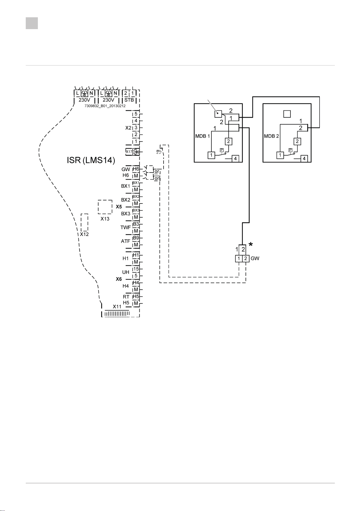
3.1 Anschlussplan Maximaldruckbegrenzer
Abb.1 Anschlussplan Maximaldruckbegrenzer
VP
GWI
RA-0001873
GWI Kesselinterner Gasdruckwächter
VP Verdrahtungspunkt
MDB 1/2 Maximaldruckbegrenzer 1/2
GW Klemme Gasdruckwächter
*Vorhandene Verdrahtungsbrücke entfernen und
Maximaldruckbegrenzer an Klemme GW
anschließen
de 3 Technische Angaben
6 7309871 - 03 - 20022020
4 Produktbeschreibung
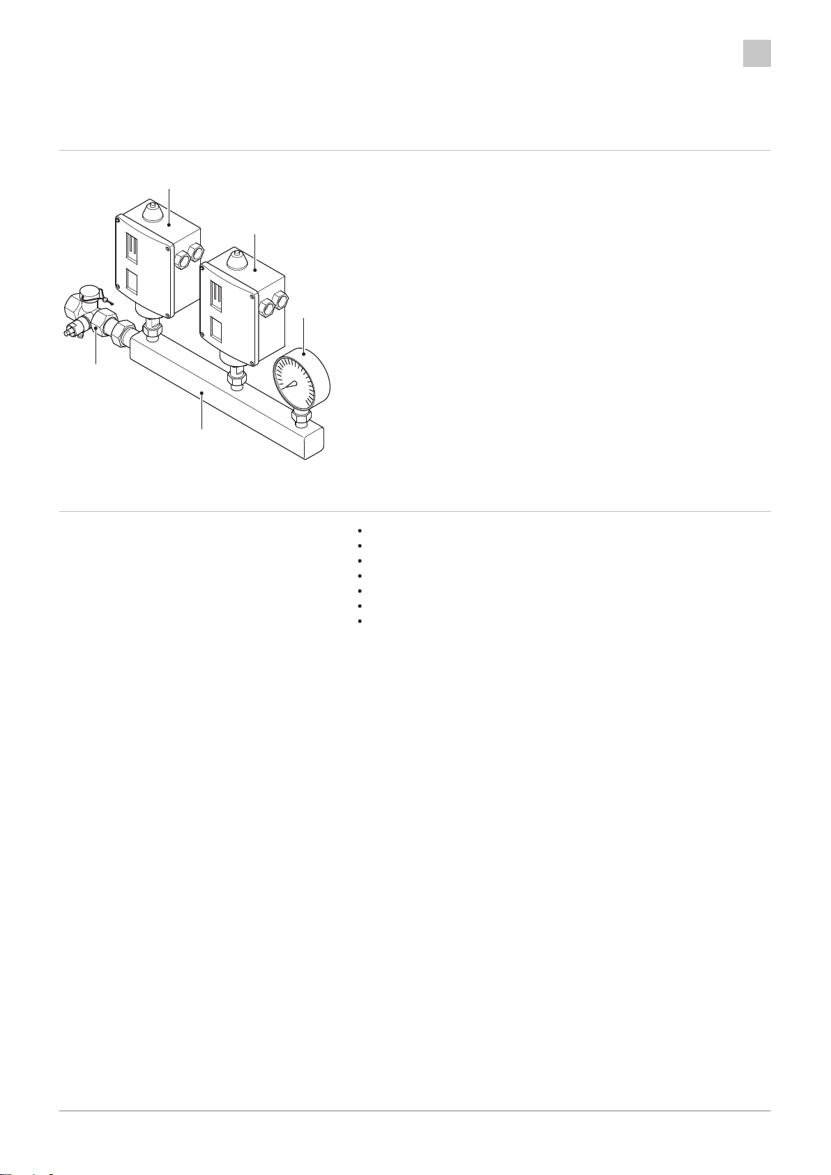
4.1 Überblick
1Maximaldruckbegrenzer
2Manometer
3Armaturenbalken
4Kappenventil
4.2 Lieferumfang SIS 3 SGB
1 Stck. Armaturenbalken
2 Stck. Maximaldruckbegrenzer Danfoss
1 Stck. Manometer
1 Stck. Kappenventil
3 Stck. Dichtung
1 Stck. Kabelset
1 Stck. Montageanleitung
MAX.
RESET
IP66
MAX.
RESET
IP66
RA-0001872
2
1
1
3
4
4 Produktbeschreibung de
7309871 - 03 - 20022020 7

5 Installation
5.1 Montage
5.1.1 Mounting the SIS 3 SGB
1. Kappenventil gemäß
Abb.
am Anschluss für die Sicherheitsgruppe
(SGB-Vorlauf) eindichten.
2. Armaturenbalken gemäß
Abb.
am zuvor installierten Kappenventil
eindichten.
3. Maximaldruckbegrenzer gemäß
Abb.
mit Dichtungen an den
Anschlüssen des Armaturenbalkens anschließen.
4. Manometer gemäß
Abb.
mit Dichtungen an den Anschlüssen des
Armaturenbalkens anschließen.
5. Elektrische Installation der Maximaldruckbegrenzer durchführen.
Abb.2 Eindichten des Kappenventils
1
RA-0001869
Abb.3 Eindichten des Armaturenbalkens
2
RA-0001870
3
RA-0001871
MAX.
RESET
IP66
MAX.
RESET
IP66
4
de 5 Installation
8 7309871 - 03 - 20022020
5.2 Elektrische Anschlüsse
5.2.1 Elektroanschluss (allgemein)
Stromschlaggefahr!
Lebensgefahr durch unsachgemäße Arbeiten!
Alle mit der Installation verbundenen Elektroarbeiten dürfen nur
von einer elektrotechnisch ausgebildeten Fachkraft durchgeführt
werden!
Stromschlaggefahr!
Vor allen Arbeiten den Kessel spannungslos schalten.
Vorsicht!
Alle Leitungen müssen innerhalb der Kesselverkleidung in den
vorgesehenen Kabelschellen verlegt und in den vorhandenen
Zugentlastungen des Schaltfeldes festgesetzt werden. Bei
bodenstehenden Kesseln müssen die Leitungen außerdem in den
Zugentlastungen an der Rückseite des Kessels festgesetzt
werden.
Wichtig:
Bei der Installation sind in Deutschland die VDE- und örtlichen
Bestimmungen, in allen anderen Ländern die einschlägigen
Vorschriften zu beachten.
5.2.2 Anschluss der Maximaldruckbegrenzer
Stromschlaggefahr!
Stromschlaggefahr! Vor der Durchführung von
Installationsarbeiten ist der Kessel spannungslos zu schalten und
gegen Wiedereinschalten zu sichern!
Nach erfolgter Montage sind die Maximaldruckbegrenzer gemäß
Anschlussplan
am integrierten Systemregler ISR LMS anzuschließen.
Weitere Informationen siehe
Anschlussplan Maximaldruckbegrenzer, Seite 6
5 Installation de
7309871 - 03 - 20022020 9

de 5 Installation
10 7309871 - 03 - 20022020
Table of contents
Languages:
Other BRÖTJE Relay manuals


