Bradco TS10 Product manual

800-456-7100 I www.paladinlcg.com 503 Gay Street, Delhi, IA 52223, United States of America
SERIALNUMBER:___________________ ManualNumber:OM757
PartNumber:75657
MODELNUMBER:___________________ Rev.
OPERATOR’SANDPARTS
MANUAL
TS10TREESHEAR
11272 1-25-10-2


TABLE OF CONTENTS
11287 8-20-08
PREFACE .......................................................................................................................................................... 3
SAFETY PRECAUTIONS
SAFETY STATEMENTS ...........................................................................................................................5
GENERAL SAFETY PRECAUTIONS....................................................................................................5-7
EQUIPMENT SAFETY PRECAUTIONS ...............................................................................................8-9
DECALS
DECAL PLACEMENT............................................................................................................................. 10
DECALS ................................................................................................................................................. 11
INSTALLATION..............................................................................................................................................12
OPERATINg INSTRUCTIONS
GENERAL INFORMATION.....................................................................................................................13
POTENTIAL HAZARDS..........................................................................................................................13
IDENTIFY THE APPROPRIATE FELLING DIRECTION ........................................................................14
DETERMINE TREE HEIGHT ................................................................................................................. 14
DETERMINE WORK AREA....................................................................................................................14
PUSH OVER BAR ADJUSTMENT ......................................................................................................... 15
OPERATION...........................................................................................................................................15
mAINTENANCE AND SERVICE
GENERAL MAINTENANCE & LUBRICATION .......................................................................................16
DAILY......................................................................................................................................................16
EVERY 40 HOURS.................................................................................................................................16
BLADE ADJUSTMENT...........................................................................................................................17
BLADE SHARPENING ........................................................................................................................... 17
TROUBLEShOOTINg................................................................................................................................. 18
SPECIFICATIONS
BOLT TORQUE SPECIFICATIONS........................................................................................................19
TREE SPADE SPECIFICATIONS ..........................................................................................................20
LImITED wARRANTY .................................................................................................................................21
PARTS
TS10 TREE SHEAR ASSEMBLY ......................................................................................................22-23
75657
1

THIS PAGE
IS INTENTIONALLY
BLANK
2
75657

PREFACE
10344 8-20-05
GENERAL COMMENTS
Congratulations on the purchase of your new BRADCO product! This product was care-
fully designed and manufactured to give you many years of dependable service. Only minor
maintenance (such as cleaning and lubricating) is required to keep it in top working condition.
Be sure to observe all maintenance procedures and safety precautions in this manual and on
any safety decals located on the product and on any equipment on which the attachment is
mounted.
This manual has been designed to help you do a better, safer job. Read this manual
carefully and become familiar with its contents.
WARNING! Never let anyone operate this unit without reading the "Safety Precautions"
and "Operating Instructions" sections of this manual.
Always choose hard, level ground to park the vehicle on and set the brake
so the unit cannot roll.
Unless noted otherwise, right and left sides are determined from the operator’s control
position when facing the attachment.
NOTE: The illustrations and data used in this manual were current (according to the
information available to us) at the time of printing, however, we reserve the right to rede-
sign and change the attachment as may be necessary without notication.
BEFORE OPERATION
The primary responsibility for safety with this equipment falls to the operator. Make
sure the equipment is operated only by trained individuals that have read and understand this
manual. If there is any portion of this manual or function you do not understand, contact your
local authorized dealer or the manufacturer.
SAFETY ALERT SYMBOL
This is the "Safety Alert Symbol" used by this industry. This symbol is used to
warn of possible injury. Be sure to read all warnings carefully. They are included
for your safety and for the safety of others working with you.
SERVICE
When servicing your product, remember to use only manufacturer replacement parts.
Substitute parts may not meet the standards required for safe, dependable operation.
To facilitate parts ordering, record the model and serial number of your unit in the space
provided on the cover of this manual. This information may be obtained from the identication
plate located on the product.
The parts department needs this information to insure that you receive the correct parts
for your specic model.
75657
3

THIS PAGE
IS INTENTIONALLY
BLANK
4
75657

10338 8-16-05
SAFETY STATEMENTS
DANGER
GENERAL SAFETY PRECAUTIONS
WARNING! READ MANUAL PRIOR TO INSTALLATION
Improper installation, operation, or maintenance of this equipment could result in
serious injury or death. Operators and maintenance personnel should read this man-
ual, as well as all manuals related to this equipment and the prime mover thoroughly
before beginning installation, operation, or maintenance. FOLLOW ALL SAFETY
INSTRUCTIONS IN THIS MANUAL AND THE PRIME MOVER’S MANUAL(S).
READ AND UNDERSTAND ALL SAFETY STATEMENTS
Read all safety decals and safety statements in all manuals prior to operating or
working on this equipment. Know and obey all OSHA regulations, local laws, and
other professional guidelines for your operation. Know and follow good work
practices when assembling, maintaining, repairing, mounting, removing, or operating
this equipment.
KNOW YOUR EQUIPMENT
Know your equipment’s capabilities, dimensions, and operations before operating.
Visually inspect your equipment before you start, and never operate equipment that
is not in proper working order with all safety devices intact. Check all hardware to
ensure it is tight. Make certain that all locking pins, latches, and connection devices
are properly installed and secured. Remove and replace any damaged, fatigued, or
excessively worn parts. Make certain all safety decals are in place and are legible.
Keep decals clean, and replace them if they become worn or hard to read.
WARNING
CAUTION
THIS SIGNAL WORD IS USED WHERE SERIOUS INJURY OR DEATH
WILL RESULT IF THE INSTRUCTIONS ARE NOT FOLLOWED PROPERLY.
THIS SIGNAL WORD IS USED WHERE SERIOUS INJURY OR DEATH
COULD RESULT IF THE INSTRUCTIONS ARE NOT FOLLOWED PROPERLY.
THIS SIGNAL WORD IS USED WHERE MINOR INJURY COULD RESULT IF
THE INSTRUCTIONS ARE NOT FOLLOWED PROPERLY.
NOTICE INDICATES A PROPERTY DAMAGE MESSAGE.
NOTICE
THIS SYMBOL BY ITSELF OR WITH A WARNING WORD THROUGHOUT THIS MAN-
UAL IS USED TO CALL YOUR ATTENTION TO INSTRUCTIONS INVOLVING YOUR
PERSONAL SAFETY OR THE SAFETY OF OTHERS. FAILURE TO FOLLOW THESE
INSTRUCTIONS CAN RESULT IN INJURY OR DEATH.
75657
5

GENERAL SAFETY PRECAUTIONS
WARNING! PROTECT AGAINST FLYING DEBRIS
Always wear proper safety glasses, goggles, or a face shield when driving pins in or
out, or when any operation causes dust, ying debris, or any other hazardous mate-
rial.
WARNING! LOWER OR SUPPORT RAISED EQUIPMENT
Do not work under raised booms without supporting them. Do not use support mate-
rial made of concrete blocks, logs, buckets, barrels, or any other material that could
suddenly collapse or shift positions. Make sure support material is solid, not de-
cayed, warped, twisted, or tapered. Lower booms to ground level or on blocks. Lower
booms and attachments to the ground before leaving the cab or operator’s station.
WARNING! USE CARE WITH HYDRAULIC FLUID PRESSURE
Hydraulic uid under pressure can penetrate the skin and cause serious injury or
death. Hydraulic leaks under pressure may not be visible. Before connecting or dis-
connecting hydraulic hoses, read your prime mover’s operator’s manual for detailed
instructions on connecting and disconnecting hydraulic hoses or ttings.
•Keep unprotected body parts, such as face, eyes, and arms as far away as
possible from a suspected leak. Flesh injected with hydraulic uid may develop
gangrene or other permanent disabilities.
• If injured by injected uid, see a doctor at once. If your doctor is not familiar with
this type of injury, ask him to research it immediately to determine proper treat-
ment.
• Wear safety glasses, protective clothing, and use a piece of cardboard or wood
when searching for hydraulic leaks. DO NOT USE YOUR HANDS!
SEE ILLUSTRATION.
CARDBOARD
HYDRAULIC HOSE
OR FITTING
MAGNIFYING GLASS
10339 8-16-05
6
75657

GENERAL SAFETY PRECAUTIONS
10340 8-16-05
WARNING! DO NOT MODIFY MACHINE OR ATTACHMENTS
Modications may weaken the integrity of the attachment and may impair the func-
tion, safety, life, and performance of the attachment. When making repairs, use only
the manufacturer’s genuine parts, following authorized instructions. Other parts may
be substandard in t and quality. Never modify any ROPS (Roll Over Protection
Structure) or FOPS (Falling Object Protective Structure) equipment or device. Any
modications must be authorized in writing by the manufacturer.
WARNING! SAFELY MAINTAIN AND REPAIR EQUIPMENT
•Do not wear loose clothing or any accessories that can catch in moving parts. If
you have long hair, cover or secure it so that it does not become entangled in the
equipment.
• Work on a level surface in a well-lit area.
• Use properly grounded electrical outlets and tools.
• Use the correct tools for the job at hand. Make sure they are in good condition for
the task required.
• Wear the protective equipment specied by the tool manufacturer.
SAFELY OPERATE EQUIPMENT
Do not operate equipment until you are completely trained by a qualied operator
in how to use the controls, know its capabilities, dimensions, and all safety require-
ments. See your machine’s manual for these instructions.
•Keep all step plates, grab bars, pedals, and controls free of dirt, grease, debris,
and oil.
• Never allow anyone to be around the equipment when it is operating.
• Do not allow riders on the attachment or the prime mover.
• Do not operate the equipment from anywhere other than the correct operator’s
position.
• Never leave equipment unattended with the engine running, or with this attach-
ment in a raised position.
• Do not alter or remove any safety feature from the prime mover or this attach-
ment.
• Know your work site safety rules as well as trafc rules and ow. When in doubt
on any safety issue, contact your supervisor or safety coordinator for an explana-
tion.
75657
7

11275 8-13-08
EQUIPMENT SAFETY PRECAUTIONS
WARNING! KNOW WHERE UTILITIES ARE
Observe overhead electrical and other utility lines. Be sure equipment and any trees
being sheared will clear them. Electrocution could occur if trees contact or damage
overhead electrical lines.
WARNING! EXPOSURE TO RESPIRABLE CRYSTALLINE SILICA DUST
ALONG WITH OTHER HAZARDOUS DUSTS MAY CAUSE SE-
RIOUS OR FATAL RESPIRATORY DISEASE.
It is recommended to use dust suppression, dust collection and if necessary person-
al protective equipment during the operation of any attachment that may cause high
levels of dust.
WARNING! REMOVE PAINT BEFORE WELDING OR HEATING
Hazardous fumes/dust can be generated when paint is heated by welding, soldering
or using a torch. Do all work outside or in a well ventilated area and dispose of paint
and solvent properly. Remove paint before welding or heating.
When sanding or grinding paint, avoid breathing the dust. Wear an approved respira-
tor. If you use solvent or paint stripper, remove stripper with soap and water before
welding. Remove solvent or paint stripper containers and other ammable material
from area. Allow fumes to disperse at least 15 minutes before welding or heating.
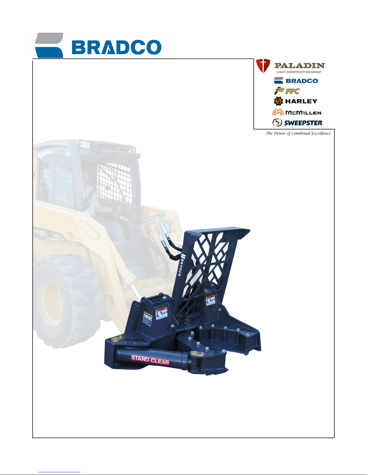
OPERATING THE TREE SHEAR
Block off work area from bystanders, livestock, etc. Do not operate if people are in
the felling area. Stop operation if bystanders or livestock enter the work area.
Operate only from the operator’s station.
Do not operate without adequate operator protection.
Operator enclosure must comply with regulations and provide a safe operating envi-
ronment for the risks associated with shearing trees.
Do not operate the tree shear with the push over bar removed.
Do not shear from the downhill side of a slope or hill.
Do not operate in high winds.
Do not shear trees with a diameter larger than the 10” stated capacity of the TS10
Tree Shear.
Do not fell (shear) a tree that is leaning across the line of machine travel.
An operator must not use drugs or alcohol, which can change his or her alertness or
coordination. An operator taking prescription or over-the-counter drugs should seek
medical advice on whether or not he or she can safely operate equipment.
Before exiting the prime mover, lower the unit to the ground, turn off the prime
mover’s engine, remove the key and apply the brakes.
Do not use the tree shear blades as a step when climbing in or out of the prime
mover.
Be alert to changes in the work area. Watch out for bystanders, changes in weather
and soil conditions.
•
•
•
•
•
•
•
•
•
•
•
•
•
8
75657

TRANSPORTING THE TREE SHEAR
When driving on public roads use safety lights, reectors, Slow Moving Vehicle signs
etc., to prevent accidents. Check local government regulations that may affect you.
Do not drive close to ditches, excavations, etc., cave in could result.
Do not smoke when refueling the prime mover. Allow room in the fuel tank for
expansion. Wipe up any spilled fuel. Secure cap tightly when done.
When transporting keep the tree shear as low as the terrain will allow.
MAINTAINING THE TREE SHEAR
Before performing maintenance, lower the attachment to the ground, apply the
brakes, turn off the engine, and remove the key.
Never perform any work on the attachment unless you are authorized and qualied
to do so. Always read the operator service manuals before any repair is made. After
completing maintenance or repair, check for correct functioning of the tree shear.
If not functioning properly, always tag “DO NOT OPERATE” until all problems are
corrected.
Worn, damaged, or illegible safety decals must be replaced. New safety decals can
be ordered from BRADCO.
Never make hydraulic repairs while the system is under pressure. Serious personal
injury or death could result.
Never work under a raised attachment.
Replace all safety shields and guards (including the push bar) when done performing
maintenance. Do not operate tree shear with protective equipment removed.
•
•
•
•
•
•
•
•
•
•
EQUIPMENT SAFETY PRECAUTIONS
11276 8-13-08
75657
9

DECALS
11273 8-12-08
DECAL PLACEMENT
GENERAL INFORMATION
The diagrams on this page show the location of all the decals used on the TS10 Tree
Shear. The decals are identied by their part numbers, with the reductions of the actual decals
located on the following pages. Use this information to order replacements for lost or damaged
decals. Be sure to read all decals before operating the tree shear. They contain information
you need to know for both safety and attachment longevity. All logo’s and model numbers can
be purchased from your local dealer.
IMPORTANT: Keep all safety decals clean and legible. Replace all missing, illegible or damaged safety decals. When replac-
ing parts with safety decals attached, the safety decals must also be replaced.
REPLACING SAFETY DECALS: Clean the area of application with a nonammable solvent, then wash the same area with
soap and water. Allow the surface to dry. Remove the backing from the safety decal, exposing the adhesive surface. Apply the
safety decal to the position shown in the diagram above, and smooth out any bubbles.
41119
LOGO
SERIAL TAG
LOCATION
4338
41118
41117
MODEL
NUMBER
LOGO
41119
40151
40161
40161
10
75657

DECALS
11274 8-12-08
PART #41119
WARNING! CUTTING OR SEVER DECAL
PART #41117
WARNING! READ MANUAL
PART #40151
WARNING! HIGH PRESSURE FLUID
PART #41118
DANGER! ELECTROCUTION OR CRUSHING DECAL
PART #40161
DANGER STAND CLEAR DECAL
PART #338
MADE IN U.S.A.
75657
11

INSTALLATION
11279 8-13-08
INSTALLATION
Your TS10 Tree Shear was shipped complete with the hydraulic hoses and couplers
installed.
Install the tree shear by following your power unit operator's manual for installing an at-
tachment.
WARNING! To Avoid Serious Personal Injury, make sure the tree shear is securely
latched to the attachment mechanism of your unit. Failure to do so could
result in separation of the shear from the unit.
WARNING! The prime mover must be equipped with an operator enclosure that will
comply with regulations and provide a safe operating environment for the
risks associated with shearing trees up to 10” in diameter.
Connect the hydraulic quick couplers to the auxiliary hydraulics and route the hoses in
such a fashion as to prevent chang and pinching.
Start engine and slowly cycle the shear cylinder several times to purge system of air,
and check for proper hydraulic connection, hose routing, and hose length.
Check the attachment for proper assembly, installation, and hydraulic leaks.
DETACHING
On rm level ground, close the blades and lower the boom arms completely down on
the frame until the shear is level and approximately 2" off the ground.
Turn off the engine. Move the control levers back and forth to relieve pressure in line.
Disconnect couplers.
NOTE: Connect couplers together or install caps to prevent contaminants from entering
the hydraulic system.
Follow your power unit operator's manual for detaching (removing) an attachment.
NOTE: Frequent lubrication of grease ttings at the ends of the cylinder and the pivot
point with a multi-purpose grease will greatly increase life of the product.
STORAGE
1. Clean the unit thoroughly, removing all mud, dirt, and grease.
2. Inspect for visible signs of wear, breakage, or damage. Order any parts required and
make the necessary repairs to avoid delays when starting next season.
3. Tighten loose nuts, capscrews, and hydraulic connections.
4. Cap hydraulic couplers to protect against contaminates.
5. Touch up all unpainted surfaces with paint, to prevent rust.
6. Coat the exposed portion of the cylinder rod with grease.
7. Store the unit in a dry and protected place. Leaving the unit outside will materially short-
en its life.
12
75657

OPERATION
11280 8-13-08
GENERAL INFORMATION
The BRADCO TS10 hydraulic actuated Tree Shear with push over bar is perfect for clear-
ing small trees and scrub brush (up to 10” in diameter) from pastures, building sites and wild
re fuel control operations. The TS10 attaches to the quick attach mechanism of your skid steer.
Due to this arrangement, thorough knowledge of the skid steer is necessary for machine opera-
tion. Read and understand your power units operator’s manual before attempting to use the tree
shear.
To “fell a tree” means more than just cutting it down. Felling means to cut the tree in a way
that it falls in the desired direction and results in the least damage to the tree. To safely fell any
tree you must rst eliminate or at least minimize exposure to potential hazards found in the tree
and in the surrounding area. Secondly determine the felling direction and work area and last but
not least, use the proper shearing technique to ensure the tree falls in the desired direction.
POTENTIAL HAZARDS: Determine the hazards that exist for the area and types of trees that
your are working with and eliminate or minimize your exposure to these hazards.
POTENTIAL HAZARD WAYS TO ELIMINATE, MINIMIZE OR AVOID
HAZARD
THROWBACK: As the tree falls through other trees
or lands on objects, those objects or branches may
get thrown back towards the operator.
If possible, avoid felling into other trees or onto
objects.
TERRAIN: If the tree falls onto stumps, rocks, or
uneven ground, a hazard may be created.
If possible, move the obstacle, or change the fell-
ing direction.
LODGED TREE: A tree that has not fallen com-
pletely to the ground because it is lodged or lean-
ing against another tree.
Do not work in the presence of a lodged tree.
Have these pushed or pulled down.
WIDOWMAKER: Broken off limbs that are hang-
ing freely in the trees to be felled or in the trees
close by.
Knock them down or pull them down. Avoid work-
ing underneath them.
SNAG: Standing dead tree, standing broken tree,
or a standing rotted tree.
Remove these with a “machine” such as the tree
shear, or avoid them by at least two tree lengths.
SPRING POLE: A tree, segment of a tree, limb,
or sapling which is under stress or tension due to
the pressure or weight of another tree or object.
Use a “machine” or possibly a chain saw to re-
lease the tension.
EXTREME WEATHER: Strong wind. Do not fell tress during high winds.
ENTANGLEMENT: Vines or limbs of other
trees intertwined with the limbs of the tree to
be felled.
Undo the entanglement if possible, or use a
“machine” such as the tree shear to fell the
tree.
RESOURCES: Other workers or machines in
the immediate area.
Request the workers or machines be moved
and block off the work area.
NOTE: Potential hazards and descriptions have been taken from OSHA standard 1910.266 (h)
75657
13

OPERATION
11281 8-13-08
IDENTIFY THE APPROPRIATE FELLING DIRECTION: Determining the desired direction that
the tree is to fall is an important step and there are numerous factors to consider. Visualize the
fall path and identify hazards. Finding a clear path will eliminate lodged trees and throwbacks.
When working with a leaning tree, it generally easier to fell the tree in the direction that it is al-
ready leaning and when working on a slope take into consideration the chance that the tree will
roll or slide. Whenever possible, fell the tree so the butt faces the direction of removal. This will
assist you in removing the tree after it is down.
DETERMINE TREE HEIGHT: There are numerous ways to check for tree height. We have listed
just a couple.
SHADOW METHOD:
a. Know your exact height (in the shoes you will be wearing when measuring the tree.
b. Stand next to the tree. (Bright sunny day works best.)
c. Measure your shadow from your feet to the tip of your shadow. NOTE: If you are alone, place a
rock on the ground and then position yourself so the tip of your shadow is at the rock then mea-
sure from where you are standing to the rock.
d. Measure the length of the tree’s shadow. From the base of the tree to the tip of the shadow.
e. Calculate to obtain the trees height. (Be sure to use the same units of measure, inches to inches
or feet to feet.) To calculate the height of the tree multiply the length of the tree shadow by your
height and then divide the resulting number by the length of your shadow.
(length of tree shadow) X (your height) divided by (your shadow length) = (tree height)
Example: your height @ 5’ tall, multiplied by the trees shadow @100’ and then divided by your shadow’s length of
8’ gives you a tree height of 62.5.
PENCIL METHOD: (This method requires an assistant.)
a. Stand far enough from the tree so you can view the whole tree, without moving your head and as
level with the tree as possible.
b. Have a friend stand near the tree.
c. Hold up a small pencil or straight stick in one hand and stretch your arm out so the pencil is at
arm’s length in front of you (between you and the tree).
d. Close one eye and adjust the pencil up/down so that you can sight the very top of the tree at
the tip of the pencil. Move your thumb up or down so the tip of your thumbnail is aligned with the
tree’s base.
e. Rotate your arm so that the pencil is horizontal (parallel to the ground). Keep your arm help
straight out and make sure your thumbnail is still aligned with the tree’s base.
f. Have your friend move so that you can sight his/her feet through the tip of your pencil. (You will
have to direct your friend left, right, backwards or sideways using the hand that is not holding the
pencil.
g. Measure the distance between your friend and the tree. This is the height of the tree.
DETERMINE THE WORK AREA: The work area shall be at least two tree lengths of the tree
being felled. A distance greater than two tree lengths shall be maintained on any slope where
rolling or sliding of trees or logs is reasonably foreseen. No one should enter the work area until
the machine operator has acknowledged that is it safe to do so.
14
75657

WARNING! Block off the work area from bystanders and livestock and etc. Do not oper-
ate the tree shear if people are in the felling area Stop operation immediately
if people or livestock enter the work area.
WARNING! Before exiting the prime mover, lower the attachment to the ground, apply
the parking brakes, turn off the engine and remove the key.
PUSH OVER BAR ADJUSTMENT
The push over bar is standard from the factory and installed in the back position. The front
position should be used when shearing trees on a hill to position the push bar back towards the
operator therefore allowing the blades to shear the tree without the push bar interfering.
WARNING! When shearing a tree on a slope always approach the tree from an uphill
direction. Never attempt to fell a tree from the side or from a downhill direc-
tion.
Do not operate the tree shear with the Push Over Bar removed.
OPERATION
Read and understand all warnings and precautions in this manual and on the machine
before operating the tree shear. The BRADCO tree shear is relatively simple to use and with
a little practice, you should become procient in its operation and able to develop procedures
suitable to your particular situation. Remember, the TS10 is designed for trees up to but not
exceeding 10” in diameter.
WARNING! The prime mover must be equipped with an operator enclosure that will
comply with regulations and provide a safe operating environment for the
risks associated with shearing trees up to 10” in diameter.
Do not operate the tree shear with the Push Over Bar removed.
1. Approach the tree with the blades completely open. Position the shear with the blades on
each side of the tree at the point where the cut is to be made.
2. Tilt the shear forward a little to provide a slight angle to the cutting blades which will as-
sist in the tree falling away from the machine and operator.
3. Activate the auxiliary hydraulic which will close the blades on the shear.
NOTE: As an extra precaution, as the blades come completely together tilt the shear
forward and use the push over bar to help direct the tree. Backing up the prime mover
slightly will also assist in ensuring the tree will fall forward.
OPERATION
11282 8-13-08
75657
15

MAINTENANCE & SERVICE
11283 8-18-08
GENERAL INFORMATION
Regular maintenance is the key to long equipment life and safe operation. Maintenance
requirements have been reduced to the absolute minimum. However, it is very important that
these maintenance functions be performed as described below.
DAILY
• Check all bolts and nuts for tightness.
• Replace any missing bolts or nuts with approved replacement parts.
• Check hydraulic system for hydraulic oil leaks. See procedure below.
• Visually inspect the machine for worn parts or cracked welds, and repair
as necessary.
• Visually inspect the machine for worn, blades. Repair or replace as necessary.
Lubricategreasettingsonbothendsofthecylinderandthearmatthemainpivot
point.
Clean rotor of any accumulated debris and dirt.
EVERY 40 HOURS
WARNING! Escapinguidunderpressurecanhavesufcientforcetopenetratethe
skin,causingseriouspersonalinjury.Fluidescapingfromaverysmall
holecanbealmostinvisible.Useapieceofcardboardorwood,ratherthan
hands,tosearchforsuspectedleaks.
Keepunprotectedbodyparts,suchasface,eyes,andarmsasfarawayas
possiblefromasuspectedleak.Fleshinjectedwithhydraulicuidmay
developgangreneorotherpermanentdisabilities.
Ifinjuredbyinjecteduid,seeadoctoratonce.Ifyourdoctorisnotfamil-
iarwiththistypeofinjury,askhimtoresearchitimmediatelytodetermine
propertreatment.
•
•
•
CARDBOARD
HYDRAULIC HOSE
OR FITTING MAGNIFYING GLASS
IMPORTANT:Whenreplacingparts,useonlyfactoryapprovedreplacementparts.Manu-
facturerwillnotclaimresponsibilityforuseofunapprovedpartsoraccessories,and/or
otherdamagesasaresultoftheiruse.
16
75657

MAINTENANCE & SERVICE
11284 8-19-08
BLADE ADJUSTMENT
The blade on the arm of the tree shear is adjustable and should be checked before
operation. The cutting edge on the blades should always be parallel to each other with as little
gap as possible.
If the blades have worn irregularly or shifted during operation and are not parallel, ad-
justing one adjuster wedge may be required to bring them into alignment.
1. Slightly loosen the 5 bolts on the arm blade.
2. With the shear arm completely closed, position the blade until the cutting edges are
parellel and just about touching. Tighten or loosen the .50” UNC X 4” sockethead cap-
screws on the adjusting wedges to maintain the correct positioning of the blades.
NOTE: Do not allow the blades to make contact during shearing.
3. Be sure the blade is tight against the adjusting wedges and then tighten the .75” UNC X
8” blade bolts. Torque bolts to 270-324 ft. lbs.
INCORRECT BLADE POSITION
(BLADES NOT PARELLEL AND HITTING ON
THE INSIDE.)
CORRECT PARELLEL BLADE POSITION
TO CORRECT BLADE POSITIONING:
TIGHTEN THE CAPSCREW ON THE OUTSIDE ADJUSTING WEDGE AND LOOSEN THE CAPSCREW ON
THE INSIDE ADJUSTING WEDGE UNTIL BLADES ARE PARELLEL WTH EACH OTHER.
ARM
ADJUSTING
WEDGE
BLADE ADJUSTING
WEDGE PARELLEL
ADJUSTING
WEDGE
.75” UNC X 8.00”
CAPSCREWS
.50” UNC X 4.00” SOCKETHEAD
CAPSCREWS
BLADE SHARPENING
The shear blades are sharpened at the factory to the most effective cutting angle. Main-
taining this angle is important for performance and efciency. Use the following diagram as a
guide when sharpening the blades.
1.37”
15°
30° MAINTAIN THIS CUTTING
ANGLE ON EACH SIDE
.50”
.50”
75657
17

TROUBLESHOOTING
11286 8-19-08
PROBLEM POSSIBLE CAUSE POSSIBLE REMEDY
Blades misaligned. Worn shear arm bushing.
Worn pivot pin.
Improper blade sharpening.
Irregular wearing of the blade.
Hardware or adjusting wedge loose.
Replace as necessary.
Refer to Blade Sharpening section in
manual and resharpen blade.
Sharpen if necessary and adjust
blade.
Tighten hardware and properly adjust
blade.
Blades will not stay adjusted. Maximum adjustment has already been
accomplished.
Replace blades.
insufcient power. Insufcient hydraulic ow from the
prime mover.
Loose or damaged hydraulic line.
Upper bearing failure.
O-Rings on ttings damaged.
Fittings loose or damaged.
Cylinder seals damaged.
Attempting to shear a tree larger than
recommend.
Refer to the prime mover owners
manual and verify hydraulic ow using
an inline ow meter or other attach-
ment.
Tighten or replace.
Replace as necessary
Replace if necessary.
Tighten or replace.
Replace cylinder seals.
Refer to specications.
Hydraulic cylinder not
operating
Insufcient hydraulic ow from the
prime mover.
Cylinder rod bend.
Cylinder seals damaged.
Obstruction in hydraulic lines.
Refer to the prime mover owners
manual and verify hydraulic ow using
an inline ow meter or other attach-
ment.
Replace cylinder.
Replace cylinder seals.
Remove obstruction and replace if
necessary.
18
75657
Table of contents