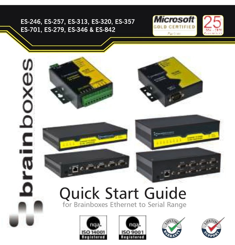
Brainboxes ES-357 User manual

Print Date: 25.06.2013
Brainboxes Limited, 18 Hurricane Drive, Liverpool International Business Park, Speke, Liverpool, Merseyside, L24 8RL
Tel: +44 (0)151 220 2500 Fax: +44 (0)151 252 0446 Web: www.Brainboxes.com Email: sales@Brainboxes.com
Brainboxes Ethernet to Serial
ES - Range Product Manual

ES Range Product Manual Version 2.9
© Copyright Brainboxes Limited 2013 Page 2 of 66
Contents
1. Introduction ............................................................................................................................................ 5
2. Before You Start..................................................................................................................................... 6
Box Contents Check list – ES-357/ES-020/ES-031/ES-042 .................................................................. 6
Box Contents Check list – ES-246/ES-257/ES-313/ES-320 .................................................................. 6
Box Contents Check list – ES-279/ES-346/ES-701/ES-842 .................................................................. 6
Requirements ......................................................................................................................................... 7
System Requirements......................................................................................................................7
Network Requirements ....................................................................................................................7
Supported Operating Systems ............................................................................................................... 7
3. Hardware Features ................................................................................................................................ 8
ES Hardware – 1 & 2 Port Devices ........................................................................................................ 8
ES Hardware – 4 & 8 Port Devices ........................................................................................................ 8
Network IP Addressing ........................................................................................................................... 9
Default Settings ...................................................................................................................................... 9
4. Installation procedures ......................................................................................................................... 10
Connecting Your ES Device ................................................................................................................. 10
Windows Installation: Boost.LAN Manager Application (shown in Windows 7) ................................... 11
Windows Installation: Device Driver (shown in Windows 7)................................................................. 12
Windows Installation: Boost.LAN Manager Application (shown in Windows 8) ................................... 14
Windows Installation: Device Driver (shown in Windows 8)................................................................. 17
5. RS-232 Settings (ES-246/ES-257/ES-701/ES-279/ES-357/ES-020) .................................................. 18
The RS-232 Standard........................................................................................................................... 18
9 Pin D Serial Port RS-232 Cables....................................................................................................... 18
9 Pin D serial port connections to another PC ..................................................................................... 18
6. RS-422/485 Settings (ES-320/ES-313/ES-346/ES-842/ES-357/ES-031/ES-042) .............................. 20
The RS-422 Standard........................................................................................................................... 20
RS-422 Operation................................................................................................................................. 20
RS-422 Full Duplex Mode .................................................................................................................... 20
RS-485 Standard .................................................................................................................................. 21
RS-485 Operation................................................................................................................................. 21
RS-422 Serial Port Cables ................................................................................................................... 23
RS-485 Serial Port Cables ................................................................................................................... 23

ES Range Product Manual Version 2.9
© Copyright Brainboxes Limited 2013 Page 3 of 66
Optional Grounding Arrangements....................................................................................................... 24
RS-485 Line Failsafe Biasing ............................................................................................................... 24
RS-485 Line Termination...................................................................................................................... 24
RS-485 Full Duplex (ES-357) ............................................................................................................... 25
RS-485 Half Duplex Autogating Mode (ES-357 Only).......................................................................... 26
RS-485 Half Duplex Mode (ES-313, ES-320, ES-346 & ES-842 only) ................................................ 27
7. Finding your Brainboxes COM port...................................................................................................... 29
Using the ES-device with your Equipment............................................................................................... 30
If you are using a COM port based application .................................................................................... 30
If you are using a socket based application ......................................................................................... 30
8. Testing the ES device .......................................................................................................................... 31
9. Advanced Configuration....................................................................................................................... 32
IP Addressing ....................................................................................................................................... 32
Port Settings ......................................................................................................................................... 33
Changing your COM label .................................................................................................................... 34
Advanced Settings – TCP/IP Settings.................................................................................................. 35
Alternate Access Methods.................................................................................................................... 36
Proxy Server Settings........................................................................................................................... 36
Device Swapping .................................................................................................................................. 36
Remote Access .................................................................................................................................... 37
Adding a remote device using Boost.LAN Manager............................................................................. 37
Serial Tunnelling................................................................................................................................... 38
Firewall Exceptions and Port Numbers ................................................................................................ 40
UPnP on/off .......................................................................................................................................... 40
Transmission Interval ........................................................................................................................... 41
10. Web Page Interface ........................................................................................................................... 42
11. Security .............................................................................................................................................. 44
Administrator Access Settings.............................................................................................................. 44
User Access Settings ........................................................................................................................... 44
MAC Address restriction....................................................................................................................... 45
Restricting “Reset/Restore Default”...................................................................................................... 46
Authentication Method.......................................................................................................................... 46
12. Exporting & Importing Device Settings .............................................................................................. 47
Exporting Device Settings .................................................................................................................... 47

ES Range Product Manual Version 2.9
© Copyright Brainboxes Limited 2013 Page 4 of 66
Importing Device Settings..................................................................................................................... 48
13. Rebooting Device............................................................................................................................... 50
Rebooting in Boost.LAN Manager ........................................................................................................ 50
Manual Reboot ..................................................................................................................................... 50
14. Restoring to Factory Default .............................................................................................................. 51
Restoring back to Factory Default Settings .......................................................................................... 51
Manual Hard Restore ........................................................................................................................... 51
15. Firmware Upgrade ............................................................................................................................. 52
16. Uninstallation...................................................................................................................................... 54
Complete Boost.LAN Suite Uninstallation. ........................................................................................... 54
Individual Device Uninstallation............................................................................................................ 54
17. Troubleshooting and Testing ............................................................................................................. 55
18. Linux support for ES devices ............................................................................................................. 58
Configuring the ES device from Linux .................................................................................................. 58
Using Cyclades Serial Client to communicate with ES device ports.................................................... 58
19. Lifetime Warranty and Support .......................................................................................................... 60
20. Technical Specifications..................................................................................................................... 61
Device specification.............................................................................................................................. 61
Network connection .......................................................................................................................61
RS-232 Serial Port ......................................................................................................................... 61
RS-422/485 Serial Port ..................................................................................................................61
Power.............................................................................................................................................61
LED indicators................................................................................................................................62
Physical..........................................................................................................................................62
Terminal Block Connector Pin out (dependent on ES Model).............................................................. 63
Storage and Operating Environment Guidelines.................................................................................. 63
21. Regulatory Approvals / Compliance................................................................................................... 64
Company Accreditation ........................................................................................................................ 64
Europe – EU Declaration of Conformity ............................................................................................... 64
WEEE Directive (Waste Electrical and Electronic Equipment) ............................................................ 64
RoHS Compliance ................................................................................................................................ 65
22. Copyright ............................................................................................................................................ 66
23. Version History................................................................................................................................... 66

ES Range Product Manual Version 2.9
© Copyright Brainboxes Limited 2013 Page 5 of 66
1. Introduction
The Brainboxes ES product range brings the benefits of fast data access and remote management to
asynchronous serial devices by connecting them to the existing local network infrastructure within
your organisation. Designed and built on-site with close collaboration between the hardware and
software teams to deliver a product that is both user-friendly and has plenty of functionality.
The ES product range offers serial devices with support for the RS-232, RS-422 (Full Duplex) and
RS-485 (Full & Half Duplex) serial port standards as well as network communication over raw TCP
and Telnet. The supplied Windows drivers allow you to use any existing software that uses COM
ports, without modification.

ES Range Product Manual Version 2.9
© Copyright Brainboxes Limited 2013 Page 6 of 66
2. Before You Start
Box Contents Check list – ES-357/ES-020/ES-031/ES-042
The following items are included with your product:
Ethernet to Serial (ES) device
Boost.LAN Product CD
Quick Start Guide
Optional Items:
Power supply unit - PW-600
DIN-Rail Mounting Kit (MK-048)
Box Contents Check list – ES-246/ES-257/ES-313/ES-320
The following items are included with your product:
Ethernet to Serial (ES) device
Boost.LAN Product CD
Quick Start Guide
Power Supply (PW-800 - Power Input 5-30V DC 1.8W Max / 1.0W Typical)
oES-246 – PW-800
oES-257 – PW-800
oES-320 – PW-800
oES-313 – PW-800
Optional Items:
DIN-Rail Mounting Kit (MK-048)
Box Contents Check list – ES-279/ES-346/ES-701/ES-842
The following items are included with your product:
Ethernet to Serial (ES) device
Boost.LAN Product CD
Quick Start Guide
Power Supply (PW-800 - Power Input 5-30V DC 1.8W Max / 1.0W Typical)
oES-279 – PW-800
oES-346 – PW-500
oES-701 – PW-800
oES-842 – PW-500
Optional Items:
DIN-Rail Mounting Kit (MK070)
Wall Mounting Kit (MK-059)
If any of the items are missing from your box or damaged in anyway please contact
support@Brainboxes.com

ES Range Product Manual Version 2.9
© Copyright Brainboxes Limited 2013 Page 7 of 66
Requirements
System Requirements
Components: Microsoft .NET Framework 2.0 (installed automatically with Boost.LAN package)
Windows Installer: Windows Installer 3.1 or later (Recommended)
Internet Explorer: If you are running Internet Explorer, then Internet Explorer 6.0 or later is required
Processor: 400 MHz Pentium processor or equivalent (Minimum); 1GHz Pentium processor or
equivalent (Recommended)
RAM: 96 MB (Minimum); 256 MB (Recommended)
Hard Disk: Up to 500 MB of available space may be required
CD or DVD Drive: Not required
Display: 800 x 600, 256 colours (Minimum); 1024 x 768 high colours, 32-bit (Recommended)
Network Requirements
Ethernet network connection (wired).
Supported Operating Systems
The ES Ethernet to Serial product range can be used in the following Microsoft Operating Systems
with the supplied Boost.LAN drivers:
Brainboxes Boost.LAN drivers have undergone Microsoft testing with the ES range. Upon passing
these tests, the drivers were signed by Microsoft, as an indication of their quality and stability.
It is also possible to use the ES device with a Linux system. See Section 18 for full details.

ES Range Product Manual Version 2.9
© Copyright Brainboxes Limited 2013 Page 8 of 66
3. Hardware Features
ES Hardware – 1 & 2 Port Devices
ES Hardware – 4 & 8 Port Devices

ES Range Product Manual Version 2.9
© Copyright Brainboxes Limited 2013 Page 9 of 66
For information on power supplies and pin outs please see Section 20 Technical Specifications.
LED Information
Status LED Green Light On
Flashing Green
Device Ready
Flashing Red & Yellow Changing Settings
Flashing between Green & Red Querying IP
Flashing between Green & Red IP Problem
Flashing Green/Red Performing Hard Reset
Flashing between Green & Yellow Problem during initialization (e.g.
Firmware Problem)
Serial Port LED Green light on Port Open
Flashing light on Data RX/TX
Ethernet LED Green light on Link established
Flashing Green Data RX / TX
Network IP Addressing
The ES device is shipped in DHCP Mode.
On connecting to the network, the device automatically checks if it is connected to a DHCP
Server. If this is the case, the DHCP server will allocate an IP address automatically to the ES
device.
If no DHCP Server is detected (e.g. you have the ES device plugged directly into the PC), the
ES device will default to an IP address of 192.168.127.254 within 60 seconds. Please ensure
the PC you’re using for configuration can communicate with the 192.168.127.xxx IP range by
setting the Ethernet port the ES device is plugged into, to an IP address in the same subnet.
If you are using the default IP address with no DHCP server, you can change to a static IP
address to avoid having to wait 60 seconds for the default address of 192.168.127.254
Default Settings
Network Setting
Device Networ
k Address
DHCP Mode
Web Server Port
80
Port Settings
RS
-
232
Port
RS
-
422
/485 Port
Baudrate
115200 115200
Databits
8 8
Stop bits
N N
Parity
1 1
Flow Control
None None
Duplex mode
Full Duplex Full Duplex
Protocol Settings
Telnet + COM port control
Mode (Server)
Telnet + COM port control Mode
(Server)

ES Range Product Manual Version 2.9
© Copyright Brainboxes Limited 2013 Page 10 of 66
4. Installation steps
PLEASE READ CAREFULLY
The “Setup” program will install the Boost.LAN Manager application.
Boost.LAN Manager application is the graphical user interface for locating and configuring all
Brainboxes’ Ethernet to Serial devices in Windows.
Boost.LAN is the COM ports device driver that you will use in Windows to access your ES
ports as standard Windows COM ports. You need Boost.LAN Manager to install the
Boost.LAN COM ports driver.
Neither Boost.LAN Manager or Boost.LAN is required if:
1. Your application speaks directly to IP addresses. (E.g. using telnet or Win sock
communication)
2. You want to remotely change the settings of the ES device via web page access
Follow the instructions below to start the installation process.
If you have any issues with installation, see Section 17
Connecting Your ES Device
1. Connect the ES device to your local network by using an Ethernet cable and plugging into the
Ethernet port connection. The ES Ethernet port will automatically detect the polarity of the
Ethernet connection so both a straight through or crossover Ethernet cable can be used.
2. Connect the power adapter or a DC power line (5-30V) to the ES power terminal block or jack
connection.
If using the Brainboxes PW-644 power supply ensures:
a. the wire marked “-“ is connected to V-
b. the wire marked “+” is connected to V+
3. Confirm the device beeps as it is turned on.
4. When the Status LED starts shows a solid green light the device is ready to use.
5. Connect the serial cable from your serial device to the port terminal block or DB 9 connector
(depending on ES model) on the ES device. See Section 20 for pin outs.
Make a note of device MAC address (on the side of the ES device, XX-XX-XX-XX-XX) as you will
need it to identify the device on your network later.

ES Range Product Manual Version 2.9
© Copyright Brainboxes Limited 2013 Page 11 of 66
Windows Installation: Boost.LAN Manager Application (Windows 7)
1. With the computer turned on, insert the Boost.LAN Driver CD. This should launch the
Brainboxes Navigation Page
Note: If the navigation page does not auto load, go to Start My Computer Right Click the
CD and select Explore. This will open the CD in Windows Explorer for browsing the contents
of the CD. Locate the “Setup” program on the CD and double click to launch. Proceed to Step
3.
2. Click “Install” to launch the Boost.LAN Setup.exe program.
3. Follow the on screen instructions to install the Boost.LAN Manager application

ES Range Product Manual Version 2.9
© Copyright Brainboxes Limited 2013 Page 12 of 66
4. When installation is complete, you should see an icon labelled “Boost.LAN Manager” on the
desktop.
Windows Installation: Device Driver (Windows 7)
1. Double click the icon labelled “Boost.LAN Manager” on the desktop to open the
application.
2. Click on the “File > Find Devices” in the top left hand side of the window. This will find any
Brainboxes Ethernet to Serial devices connected to your network.
3. You can find your Brainboxes ES-device by selecting a device and matching it with the
corresponding MAC address available in the left hand panel (see below). The MAC
address of your device is located on a sticker on the side of the ES device.
.
4. Once found, select the device and scroll to the “Tasks” section on the left hand panel.

ES Range Product Manual Version 2.9
© Copyright Brainboxes Limited 2013 Page 13 of 66
5. Click “Install Device”.
6. During the device installation you will see a timer symbol and the status of the device will
be ‘Installing driver…’.
7. Once the device is installed a pop up box will appear saying ‘Your new hardware is
installed and ready to use.’
8. In Boost.LAN Manger, the device will display a blue tick symbol showing that it is installed
and the status of the device will be ‘Ready’.
9. You can check the COM Number of the Port, by following the instructions in Section 7
Finding your Brainboxes COM port If you need to change the COM port number, see
Section 9 Changing Your COM Label)

ES Range Product Manual Version 2.9
© Copyright Brainboxes Limited 2013 Page 14 of 66
Windows Installation: Boost.LAN Manager Application (Windows 8)
With the computer turned on, insert the Boost.LAN Driver CD.
Note: If the navigation page does not auto load, go to Start My Computer Right Click the CD and
select Explore. This will open the CD in Windows Explorer for browsing the contents of the CD.
Locate the “Setup” program on the CD and double click to launch. Proceed to Step 3.
1. You will now see a purple pop up window as shown below. Click on it.
2. This will bring up a new menu. Select the ‘Open folder to view files’ option.
3. Click on the setup.exe file to begin the installation on the Boost.LAN manager application.

ES Range Product Manual Version 2.9
© Copyright Brainboxes Limited 2013 Page 15 of 66
4. When you click on the setup.exe file shown above in step 3, you will then be presented with
the below window. Press next.
5. After you have clicked next, the setup program will ask you to allow Boost.LAN Ethernet to
Serial devices through your firewall. Enable the tick box to continue the installation procedure.
6. You will now be asked to confirm whether or not you wish to carry on installing the software.
Click next.

ES Range Product Manual Version 2.9
© Copyright Brainboxes Limited 2013 Page 16 of 66
7. The software will now begin to install.
8. After the installation has finished, you will now see the below window. Click close.

ES Range Product Manual Version 2.9
© Copyright Brainboxes Limited 2013 Page 17 of 66
Windows Installation: Device Driver (Windows 8)
Double click the icon labelled “Boost.LAN Manager” on the desktop to open the application.
10. Click on the “File > Find Devices” in the top left hand side of the window. This will find any
Brainboxes Ethernet to Serial devices connected to your network.
You can find your Brainboxes ES-device by selecting a device and matching it with the
corresponding MAC address available in the left hand panel (see below). The MAC
address of your device is located on a sticker on the side of the ES device.
11. Once found, select the device and scroll to the “Tasks” section on the left hand panel.
Now click Install Device as shown below.
The device will now begin to install. During the device installation you will see a timer
symbol and the status of the device will be ‘Installing driver…’
12. In Boost.LAN Manger, the device will display a blue tick symbol showing that it is installed
and the status of the device will be ‘Ready’. Shown below.
13. You can check the COM Number of the Port, by following the instructions in Section 7
Finding your Brainboxes COM port If you need to change the COM port number, see
Section 9 Changing Your COM Label)

ES Range Product Manual Version 2.9
© Copyright Brainboxes Limited 2013 Page 18 of 66
5. RS-232 Settings (ES-246/ES-257/ES-701/ES-
279/ES-357/ES-020)
The RS-232 Standard
The RS-232 standard was introduced in 1962, it is now widely established. RS-232 is a slow speed, short
distance, single ended transmission system (i.e. only one wire per signal). Typical RS-232 maximum cable
length is 50 feet.
9 Pin D Serial Port RS-232 Cables
To connect to the RS-232 Serial Port you will need a cable terminating in a 9 way female D connector. It is
sound practice to use cables with screws fitted that will allow you to fasten the cable securely to the PC
card.
In general, you will need to make up a "cross-over" cable to correctly interface the PC to the RS-232 port of
another computer or device. Provided you have the pin outs and handshake requirements of both sides of
your RS-232 connection, the cross over cable becomes a matter of common sense. The cross-over cable
is simply to ensure that the right signals going out of one RS-232 port go into the appropriate lines of the
other RS-232 port.
9 Pin D serial port connections to another PC

ES Range Product Manual Version 2.9
© Copyright Brainboxes Limited 2013 Page 19 of 66
Suppose we want to connect the Brainboxes Serial Port to the serial port of another PC. Connect the
earth lines. Line 5 of Serial Port 2, to lines 1 & 7 of the other PC. This gives the two devices a
common earth level.
Connect the Transmit and Receive lines together. Line 3, TXD, Port 2 goes to line 3, RXD, of the
other PC. Line 2, RXD, Port 2 goes to line 2, TXD, of the other PC. This allows each to receive the
data transmitted by the other.
Connect the Port 2 DTR line, pin 4 to the other PC DCD, pin 8 and CTS, pin 5, lines. Also, connect up
the other PC DTR line, pin 20 to the Port 2 DCD, pin 1 and CTS, pin 8, lines.
This allows the receiving device to signal when it can no longer accept data. The receiving device
sets DTR false when it is unable to receive any more data. The sending device reads DTR on its CTS
and DCD pins. It should stop sending when CTS goes false.
Connect the Port 2 RTS line, pin 7, to the other PC DSR line, pin 6. Also, connect the other PC RTS
line, pin 4, to the Port 2 DSR line, pin 6. This RTS line is used to let the other device know that it is
ready for data exchange.

ES Range Product Manual Version 2.9
© Copyright Brainboxes Limited 2013 Page 20 of 66
6. RS-422/485 Settings (ES-320/ES-313/ES-346/ES-
842/ES-357/ES-031/ES-042)
The factory default setting for the ES devices is RS-422 full duplex.
DTR/DSR Handshaking is not available on 422/485 ports.
The RS-485 standard talks about the differential pair as ‘Data A’ and ‘Data B’ but line driver chip
manufacturers use the labels ‘Data+’ and ‘Data-’. ‘Data A’ is the inverting pin ‘Data-’ and ‘Data B’ is
the non-inverting pin ‘Data+’
If you can’t get the connection to work it may be because you have mistakenly connected the lines the
wrong way round.
The RS-422 Standard
The RS-422 standard defines a serial communications standard. RS-422 is a high speed and/or long
distance data transmission. Each signal is carried by a pair of wires and is thus a differential data
transmission system. Over distances up to 40 feet the maximum data rate is 10 Megabits per second,
and for distances up to 4000 feet the maximum data rate is 100 Kilobytes per second. A 120-Ohm
resistor should be used to terminate the receiving end of the line. It is generally used between one
transmitter receiver pair to ONLY one other transmitter receiver pair, but each output can drive up to
10 receivers.
RS-422 Standard -1 Driver up to 10 Receivers
Line Length Max Data Rate
40 Feet = 12m 10 Mbits/sec
400 Feet = 122m 1 Mbits/sec
4000 Feet = 1219m 100 Kbits/sec
RS-422 Operation
Generally, in RS-422 systems all 8 signal lines from the 9 pin D connector participate in the data
transfer sequence, thus 4 twisted pair cables are used. One twisted pair carries the TXD data
outwards, one pair brings the RXD data inward, another pair carries the RTS handshake outwards
and the fourth pair brings the CTS handshake inwards. There is no need to carry the ground from one
device to another. This RS-422 arrangement allows data to be transmitted and received
simultaneously since each signal has its own data cable pair. In addition, the receiver can set RTS
true so telling the transmitter on its CTS input that the receiver is ready to accept data. In this way, no
data will ever be transmitted when the receiver is unable to accept it, due to a full input buffer etc. And
so no data will be lost.
RS-422 Full Duplex Mode
This mode is generally used between one transmitter / receiver to only one other transmitter /
receiver, but it is possible for each output to drive up to 10 receivers.
Generally, in RS-422 systems, all 8 signal lines from the 9 pin D connector or terminal block
participate in the data transfer sequence. Thus 4 twisted pair cables are used. One twisted pair
carries the TXD data outwards, one pair brings the RXD data inward, another pair carries the RTS
handshaking signal outwards, and the fourth pair brings the CTS handshaking signal inwards. There
is no need to carry the ground from one device to another.
This manual suits for next models
11
Table of contents
Other Brainboxes Adapter manuals
Brainboxes
Brainboxes ES-246 User manual

Brainboxes
Brainboxes PCI Velocity RS422 User manual

Brainboxes
Brainboxes Bluetooth Adapter BL-819 User manual

Brainboxes
Brainboxes BL-500 User manual
Brainboxes
Brainboxes PCI Quad RS232 Reference manual

Brainboxes
Brainboxes BL-500 Quick start guide
Brainboxes
Brainboxes BL-554 User manual

Brainboxes
Brainboxes BL-510 User manual
Brainboxes
Brainboxes BL BL-830 User manual
Brainboxes
Brainboxes BL-565 User manual
