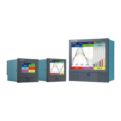
Brainchild PM1600 User manual

User Manual
Power Manager
PM1600
UMPM1600A
Brainchild Electronic Co., Ltd.
V1.3, 0 / 007

2
Content
Chapter 1 Introduction………………………………………………………………….5
1.1 Introduction of PM1600………………………………………………………………5
1.2 Caution…………………………………………………………………………………..5
1.2.1 Danger………………………………………………………………………………5
1.2.2 PRODUCT WARRA TY & CUSTOMER SUPPORT…………………………5
1.2.3 LIMITATIO OF WARRA TY……………………………………………………5
Chapter 2 Specifications………………………………………………………………..6
2.1 Main Features..........................................................................................7
2.2 Hardware Specification……………………………………………………………….8
2.3 Software Specification…………………………………………………………………9
Chapter 3 Installation and Wiring……………………………………………………12
3.1 Unpacking………………………………………………………………………………12
3.2 Installation……………………………………………………………………………...12
3.2.1 Panel Mount……………………………………………………………………….12
3.3 Wiring…………………………………………………………………………………….15
3.3.1 Rear terminal……………………………………………………………………...15
3.3.2 Digital output wiring………………………………………………………….…16
3.3.3 RS485 wiring………………………………………………………………………16
Chapter 4 Using the P 1600……………………………………..…………………..17
4.1 Ways to operate PM1600…………………………………………………………….17
4.1.1 Operation through panel keys of PM1600 Host Machine……………….17
4.1.2 Operation through PM1600 Host Machine with USB mouse…………..18
4.1.3 Operating through Web Client………………………………………………...18
4.2 General Operations……………………………………………………………………20
4.3 Function Trees........................................................................................23
4.3.1 Runtime Mode..................................................................................23
4.3.2 Configuration Mode...........................................................................24
4.4 Connecting the PM1600 with client PC…………………………………………..25
4.4.1 Pier to pier connection…………………………………………………………..25
4.4.2 etwork Connection……………………………………………………………..25
4.5 Setting the PM1600……………………………………………………………………30
Chapter 5 Run ode……………………………………………………………………..31
5.1 System Overview………………………………………………………………………31
5.2 Meter Group or Meter Display……………………………………………………..32
5.2.1 Digital Display……………………………………………………………….……32
5.2.2 Bar Chart Display………………………………………………………………..33

3
5.3 Relay Status…………………………………………………………………….………34
5.4 Individual Meter Display…………………………………………………………….35
5.4.1 Digital Display…………………………………………………………………….35
5.4.2 Summary Display………………………………………………………………..36
5.4.3 Real time Trend…………………………………………………………………..38
5.4.4 Historical Trend…………………………………………………………………..39
5.4.5 Graphical Display………………………………………………………………..40
5.5 Demand Control……………………………………………………………………….43
5.5.1 Blocking mode……………………………………………………….……………43
5.5.2 Rolling mode……………………………………………………………………….44
5.6 Time of Use……………………………………………………………………………...45
5.7 Alarm/Event Log………………………………………………………………………46
5.8 Report……………………………………………………………………………………47
5.8.1 Aggregate Daily Report………………………………………………………….47
5.8.2 Aggregate Monthly Report………………………………………………………48
5.8.3 Sub-Meter Daily Report…………………………………………………………49
5.8.4 Sub-Meter Monthly Report……………………………………………………..50
Chapter 6 Configuration ode………………………………………………………..51
6.1 System Setup…………………………………………………………………………..51
6.1.1 Date/Time Setup…………………………………………………………………52
6.1.2 Serial Communication Setup………………………………………………….53
6.1.3 Mailing List Setup………………………………………………………………..54
6.1.4 Mail Server Setup…………………………………………………………………57
6.1.5 TCP/IP Setup……………………………………………………………………..59
6.1.6 Password Modification…………………………………………………………..61
6.1.7 User’s Data Setup………………………………………………………………..61
6.2 Meter Setup……………………………………………………………………………..64
6.2.1 Basic Setup………………………………………………………………………..65
6.2.2 Measure Setup……………………………………………………………………65
6.2.3 Alarm Setup…………………………………………………………………….…66
6.2.4 Trend Setup/ DATA Recording………………………………………………..68
6.3 TOU Setup………………………………………………………………………………69
6.3.1 Season Setup……………………………………………………………………..70
6.3.2 Day Type Setup…………………………………………………………………..71
6.3.3 Holidays Setup……………………………………………………………………73
6.3.4 Rate Type Setup…………………………………………………………………..73
6.3.5 Tariff Band Setup…………………………………………………………………77
6.4 Schedule Setup………………………………………………………………………..79
6.4.1 Season Setup……………………………………………………………………...80
6.4.2 Day Type Setup……………………………………………………………………81
6.4.3 Recurring Holidays Setup………………………………………………………82
6.4.4 Special Day Type Setup…………………………………………………………83

4
6.4.5 Day Plan Setup…………………………………………………………………..84
6.4.6 Day type Setup using Calendar………………………………………………85
6.5 Demand Control Setup………………………………………………………………87
6.5.1 Parameter Setup…………………………………………………………………88
6.5.2 Load Shed Setup…………………………………………………………………91
6.6 Group Setup……………………………………………………………………………94
6.7 Data Backup……………………………………………………………………………95
Appendix…………………………………………………………………………………….96
Abbreviation………………………………………………………………………………96

5
Chapter 1 Introduction
1.1 Introduction of P 1600
PM1600 is designed for modern industrial sites, commercial facilities and
utilities power management. By integration of power monitoring, demand
control, power quality analysis, report generation and communication, PM1600
fulfills all daily power management requirements. Combines the state of art
embedded system with information networking technologies, a high
performance power supervisory control system can be built at a fairly low cost.
1.2 Caution
1.2.1 Danger
The PM1600 meter contains hazardous voltages. The meter should never be
disassembled. Failure to observe this practice can result in serious injury or
death. Any work on or near energized meters, meter sockets, or other metering
equipment can present a danger of electrical shock. It is strongly recommended
that all work should be performed only by qualified industrial electricians and
metering specialist. Brainchild assumes no responsibility if your electrical
installer does not follow the appropriate national and local electrical codes.
1.2.2 PRODUCT WARRANTY & CUSTO ER SUPPORT
Brainchild Electronic Co., Ltd. warrants all products free from defects in
material and workmanship for a period of one year from the date of shipping in
Taiwan.
Please have the serial number and a detailed problem description available
when you report any defective. If the problem concerns a particular reading,
please have all meter readings available. When returning any merchandise to
Brainchild, an approval RMA number is required.
1.2.3 LI ITATION OF WARRANTY
This warranty does not apply to defects resulting from unauthorized
modification, misuse, or use for reasons other than electrical power monitoring.
The supplied meter is not a user-serviceable product.

6
Chapter 2 Detail Specifications
Power 85~240VAC, 47~63Hz, 60VA, Maximum 23W
Display 6.4” TFT LCD, 640 x 480 pixel resolution, 24 bits colors
emory 64 MB RAM ,32 MB Flash ,16 MB DOC ,RTC(Battery
back-upped)
Interface USB: Host Port x1
Keypad: Function Key x7、Arrow Key x4
LEDx2
Digital Output Ports: 16
Contact Form: ormal on (.O.)(form A)
Relay Rating: 5A/240 VAC, life cycles 200,000 for resistive
load
CO Interface: RS-485 x 1
Protocol: ModBus over serial line
Standard
Ethernet
Communication
Protocol: ModBus over TCP/IP
Ports: Ethernet = 10/100Mbps Base T x 2
Environmental
& Physical
Operation Temperature: 5℃to 50℃
Storage Temperature: -25℃ to 60℃
Humidity: 20 to 80%RH (non-condensing)
Dimensions: 196mm (W) x 196mm (H) x 135mm (D) for panel
mount
Approval
Standards
Safety:
Protective Class:
EMC: Emission: E 61326 (E 55022 class A, E 61000-3-2,
E 61000-3-3)
Immunity: E 61326 (E 61000-4-2, E 61000-4-3,
E 61000-4-4,E 61000-4-5,E 61000-4-6,
E 61000-4-8, E 61000-4-11)

7
2.1 ain Features
Manage up to 16 units of power transducer
Flexible field communication interfaces (Ethernet and RS485) for different
power transducer connection
Rich electricity parameters and power quality display for main and
sub-feeder transducers
Easy integrated with 3
rd
party supervisory control systems
Remote power monitoring and control via intranet/internet
Electricity demand control with 16 channel load shedding
Multi-tariff management with TOU (Time-of-Use rate)
Built in web server remote monitoring and control & data download
Automatic report and alarm status sending by E-mail

8
2.2 Hardware Specification
1. Power source:85~240VAC, 47~63Hz, 60VA, max. 23W
2. Display:6.4’’ TFT LCD, 640x480 pixels, 260,000 color
3. Memory:64MB, 32MB Flash, 32MB Disc on chip (DOC)
4. Memory Storage Module:
(1)DOC:32MB/64MB to store V,I,P…etc. 54 real time power data for over
1 year(up to DOC capacity option), multi-tariff TOU report up to
3years and over 1024 alarm and event records.
(2)Support USB flash driver
5. Interface:
(1)USB Host Port x 1:to connect mouse, key board or flash drive
(2)Key:7function keys, 4 navigation keys.
6. Communication Module:
(1)RS485 x 1, communication protocol:Modbus RTU
(2)Ethernet interface(10/100Mbps Base T x 2), communication protocol:
HTTP, SMTP
7. Outputs Interface:
(1)16 digital control outputs(no voltage, normal open, 5A/240V)
(2)Control Indicator x 1(Red LED):Alarm use
(3)power Indicator x 1

9
2.3 Software Specification
1. Power demand control:
(1)Provide both blocking and rolling mode to calculate demand control.
(2)Provide shedding modes with a combination of sequence and priority
load shedding.
(3)Real time display of :
(a)control capacity
(b)selected control mode
(c)current demand
(d)average demand
(e)demand control parameters
(f)status of demand control
(g)manual load shedding
2. Monitoring of power measurement:
(1)display of real time values for each meters including:Voltage, current,
power…etc. up to 54 real-time values.
(2)digital or bar chart display for each real-time measurement data.
3. Monitoring of power quality:instant monitoring of harmonic distribution,
THD, power factor and voltage variation for each channel.
4. Display of real-time and historic trend:
(1)real-time trend display :to display trend of power information set by
users.
(2)historic display trend:
(a)to display historic trends of power consummation set by users.
(b)over a year of recorded data based on 15minuts data rate(up to
DOC capacity option).
5. Report inquiry
(1)Main Meter:
(a)various power information at different tariff can be recorded
separately.
(b) recorded information include:kWh, kvah, maximum demand, and
happening time, average and standard deviation of phase voltage
and max. and min. power factor with happening time.
(c)300 days of daily report storage.

10
(d)24 months of monthly report storage.
(2)Sub-meter:
(a)various power information at different tariff can be recorded
separately.
(b) recorded information include:kWh, kvah, maximum demand, and
happening time, average demand and load ratio.
(c)300 days of daily report storage.
(d)24 months of monthly report storage.
6. Alarm and event record
(1)Up to 29 different type of alarm(such as:over voltage, over demand,
phase imbalance, THD…etc.).
(2)On-off and time duration of each DO and system power.
(3)Up to 1024 alarm on event record.
(4)Auto email to decimated person while alarm table place.
7. Schedule control:devices can be controlled according to the pre-set season,
date and hours.
8. System setup
(1)Communication setup.
(2)etwork setup.
(3)Email setup.
(4)System time and screen protection time set up.
9. Meter setup
(1)Setup of meter address and tag name.
(2)TCP/IP ratio setup.
(3)Wiring setup.
(4)Table setup for recording information.
10. Setup for multiple tariff TOU management
(1)Start and end date setup for each season.
(2)Date type setup.
(3)Setup for recurring and non-recurring holidays.
(4)Start and end time for rate type setup(peak, non-peak rate).
11. Demand control setup
(1)according to the rate type of TOU to set up:
(a)Contracted demand capacity.
(b)Target demand.

11
(c)Alarm limit.
(d)Load shedding limit.
(2)Setup of demand control parameters:
(a)calculation algorithm.
(b)time interval of calculation.
(c)load shedding mode(sequence or priority mode).
(3)determine of load shedding mode and their involved control DO.
12. Schedule control setup
(1)Start and end time setup for each season.
(2)Date type setup.
(3)Setup for recurring holidays.
(4)calendar setup.
(5)Setup on/off time for each designated DO.
13. Information backup:historic date, reports, alarm and event records all can
be back upped through USB flash drive.
14. Remote monitoring and setup
(1)Through web browser, real time values of each meter can be monitored
and modified remotely(o additional software is required).
(2)Through web browser, system parameters can be configured.
(3)Through web browser, historic data, reports, alarm and event records
can be downloaded and saves.

12
Chapter 3 Installation and Wiring
3.1 Unpacking
If any damage been is found while unpacking, the user should contact the local
representative at once. It is suggested that the special packaging is suggested to
retain for possible future requirement.
3.2 Installation
Remove stains from this equipment using a soft, dry cloth. Don’t use
harsh chemicals, volatile solvent such as thinner or strong detergents to clean
the equipment in order to avoid deformation.
The PM1600 is designed for indoor use and not in any hazardous area. It should
be kept away from shock, vibration, and electromagnetic fields like such as
variable frequency drives, motors and transformers.
It is intended to be operated in the following environment:
Pollution Degree Level II IEC1010-1( E 61010-1 )
Temperature 5 ~ 50 ˚C
Humidity 20 ~ 80 % RH (non-condensing)
Power 90 ~ 240 VAC, 50/60 Hz
3.2.1 Panel ount
The front side

13
The left side
Panel Cutout

14

15
3.3 Wiring
Wiring Precautions
1. Care must be taken to ensure that maximum voltage rating specified on the
label is not exceeded.
2. It is recommended that near the equipment an external fuse and an external
switch rated at 2A/250 VAC should be equipped.
3. Beware not to over tighten the terminals screws. The torque should not
exceed 0.7 -m ( 6.3 Lb-in or 7.1 Kg F-cm ).
4. Connect a grounding conductor with 1.6mm diameter minimum to provide
protective grounding prior to turning on the equipment.
3.3.1 Rear terminal
LA 1: To connect with Transducers over Ethernet network
LA 2: To connect with PC for web server function

16
3.3.2 Digital output wiring
A
1
B
1
A
2
B
2
A
3
B
3
A
4
B
4
A
5
B
5
A
6
B
6
A
7
B
7
A
8
B
8
O
U
T
8
O
U
T
7
O
U
T
6
O
U
T
5
O
U
T
4
O
U
T
3
O
U
T
2
O
U
T
1
A
9
B
9
A
1
0
B
1
0
A
1
1
B
1
1
A
1
2
B
1
2
A
1
3
B
1
3
A
1
4
B
1
4
A
1
5
B
1
5
A
1
6
B
1
6
O
U
T
1
6
O
U
T
1
5
O
U
T
1
4
O
U
T
1
3
O
U
T
1
2
O
U
T
1
1
O
U
T
1
0
O
U
T
9
3.3.3 RS485 wiring
A
B
A
B
PM1600
Transducer
A
B
Transducer
․ ․ ․ ․ ․
․․․․․
․ ․ ․ ․ ․

17
Chapter 4 Using the P 1600
In this chapter, focus will be given on things that you should understand before
you actually start setting PM1600, including method of entering data,
procedure, function trees.
4.1 Ways to operate P 1600
4.1.1 Operation through panel keys of P 1600 Host achine
Press the function keys on the front panel to operate the PM1600.

18
If entering numbers or letters are required, the screen will pop-up a screen
keyboard. Simply use navigation keys and enter key to complete the filling.
4.1.2 Operation through P 1600 Host achine with USB mouse
Using USB mouse to operate PM1600, simply move the cursor to the desire item
and click the button to access, like using the mouse of PC. You can use the hard
key mixed with soft button by mouse at the same time which make you operate
the PM1600 in the field conveniently.
4.1.3 Operating through Web Client
Run the web manager program, and clicking its software function buttons, by
using the cursor directly on the selected item and click.

19
In order to use PC as a web client to access PM1600, TCP/IP setting must be
completed first. Please see page 48, TCP/IP setting. (chapter 6.1.5)

20
4.2 General Operations
Change the operation mode between Runtime and Configuration
enu navigation
Press the
Mode
key
to switch between the
Runtime mode and the
Configuration mode.
Run CFG
Press the
Esc
key
to back to the parent
menu.
ESC
Select the desired function and press
the Enter key to perform
Table of contents
Other Brainchild Measuring Instrument manuals
Popular Measuring Instrument manuals by other brands

HP
HP 3580A Operating and service manual
TES
TES TES-1362 instruction manual
socomec
socomec DIRIS B-10L Installation and operating manual

Diehl Metering
Diehl Metering Sharky 775 installation guide
PCE Health and Fitness
PCE Health and Fitness COSSEN ML-5052C operating instructions

JENCO
JENCO pH619 Operation manuals
