Brainstorm DCD-24 User manual

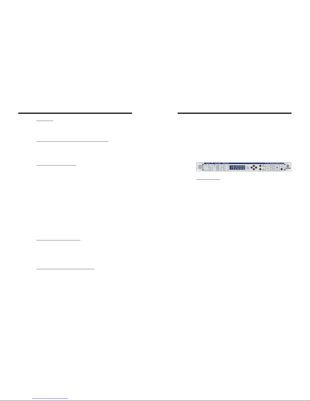
DCD-24
Word Clock Distributor
Owner’s manual
Version 1.00
October 2018
All materials herein © Brainstorm Electronics, Inc.
Brainstorm Electronics reserves the right to change or modify the contents
of this manual at any time.
Credits
Concept: AID, Brainstorm Electronics
Software: Gerry Lester
Manual: Bernard Frings, Gerry Lester
Technical Assistance: Jim Pace
Brainstorm Electronics, Inc.
www.brainstormtime.com

DCD-24 User Manual (rev 1.00) Page 3
Page 2 DCD-24 User Manual (rev 1.00)
Table of contents
1. INTRODUCTION .............................................. 2
2. INSTALLATION .............................................. 3
3. I/O’S DESCRIPTION AND CABLE REQUIREMENTS . . . . . . . . . . . . . . . . . . . 3
4. QUICK START ............................................... 4
5. FRONT PANEL DISPLAY & LED’S ................................. 5
6. NAVIGATION KEYS ........................................... 7
7. MENU NAVIGATION .......................................... 8
8. MENUS DESCRIPTION ......................................... 9
Reference ............................................... 9
Output WC Rate .......................................... 9
Outputs 9-12 ............................................ 9
9. NON-VOLATILE STORAGE ..................................... 10
10. LOCK STATUS .............................................. 10
11. DEFINING THE REFERENCE RATE ............................... 10
12. SOURCE REFERENCE FAILURE ................................. 10
13. ETHERNET................................................. 11
Ethernet IP Settings ....................................... 11
Main HTML Page ........................................ 11
14. FIRMWARE UPDATE ......................................... 12
Firmware Update Page .................................... 12
Complete vs. software .................................... 12
Programming Sequence ................................... 13
Programming Errors ...................................... 13
Loader ................................................ 14
15. APPENDIX ................................................ 15
Video Input Formats ...................................... 15
Pulled Rates............................................. 15
Multiplier Rates .......................................... 15
Word Clock phase alignment to Video ........................ 16
Factory Default Settings ................................... 16
2. Installation
2.1. UNPACKING
When unpacking the DCD-24 the following items should be in the shipping
carton:
• DCD-24 unit
• Universal Power Supply (12VDC @ 16w)
• IEC power cable
• Owner’s Manual & Registration card
2.2. INSTALLING THE DCD-24
The DCD-24 is designed to be mounted in a standard 19” rack. It requires
1U in height. Ideally, it should be located near your AD/DA and in the same
rack.
Usual precautions should be respected when wiring the DCD-24: use high
quality cables with good shield to guarantee a good signal transmission.
Keep your cables as short as possible.
Devices connected to the DCD-24’s WC outputs need to be terminated. If no
termination is provided on the device, use a BNC-T with a 75Ω termination. If
multiple devices are connected to a single DCD-24 WC output, only the last
device in the chain should be terminated. However, to preserve the integrity
of the transmission line, it is recommended that you do not daisy-chain word
clock outputs as it can significantly degrade signal quality.
3. I/O’s Description and Cable Requirements
3.1 POWER
The DCD-24 requires 12VDC @ 18W. Acceptable range is 12VDC +/-15%.
The external supply provided with the DCD-24 accepts 100 to 240 VAC input
at 50 - 60 Hz so it is suitable for use anywhere in the world.
Optionally, a second power supply can be connected to Power Input B for
redundancy. To order a second power supply contact your dealer.
☛ Insert the 4 pin plug into the rear panel jack and secure by screwing the
ring. Plug the supply into the wall using the standard IEC cable supplied.
1. Introduction
Congratulations on purchasing the DCD-24 Word Clock Distributor. The DCD-24 is
designed to distribute and generate extremely low-jitter Word Clock.
The DCD-24 can generate any standard rate, up to 192KHz, with any of the pull
coefficients. It can also generate non standard rates using the VSO.
The DCD-24 can be used as a stand-alone master clock generator or genlocked to
an external reference. As with the DCD-8, the generated frequency does not need
to be a multiple of the reference frequency. For example, the DCD-24 can generate
44.1KHz referenced to a 96KHz source.
DCD-24 User Manual (rev 1.00) Page 5
Page 4 DCD-24 User Manual (rev 1.00)
• Press the [right] navigation key once to go to the external reference menu
• Select WC
• Press the [right] key to move to the OUTPUT WC RATE
• Select FOLLOW INPUT
• Press the [set up] key again to exit SET UP (SET UP led goes out)
5. Front Panel Displays & LED’s
5.1. 6 DIGIT DISPLAY
The 6 digit display has several functions:
• Generated frequency (output frequency in Hz)
• Reference frequency (input frequency in Hz)
• VSO amount (Cents)
• Output termination (values in Ohms)
• IP address
• Name, version & serial number
The functions of the display change depending on the mode of operation:
Normal Use:
• The generated frequency (output) is normally displayed.
• To view the input frequency (reference), press and hold the [view] key.
SET UP Mode:
• In SET UP mode, the display remains unchanged, except while adjusting
the VSO (VSO ADJUST) it indicates the amount of VSO in Cents.
• To view the output termination, press and hold the [view] key. To view
another output, use the [up] or [down] key while still holding the [view] key.
The display has 2 other special functions:
IP Address:
To view the IP address, press and hold the [set up] key.
Start Up Banner:
When the unit is powered up, the display shows the following three banners,
each lasting approx 2 sec:
“DCD-24” -- name
“1.00“ -- version
“1234” -- serial number
The banner can be cancelled by hitting any switch.
3.2 ETHERNET
The Ethernet port is used to connect the DCD-24 via TCP/IP protocol to access the
unit remotely and to upload firmware from any computer on the network.
Connector: RJ45 jack
☛ Use a standard Ethernet cat5 cable with RJ45 plugs.
3.3 UNIVERSAL REFERENCE INPUT & TERMINATION SWITCH
Input accepts WC, AES (AES-3id unbalanced), 10MHz and HD and SD video sync
(see Appendix 1 for a list of supported video formats).
The switch enables 75Ω termination
Connector: BNC
☛ Use a standard 75Ω BNC cable.
3.4 WORD CLOCK OUTPUTS 1-24
24 BNC Connectors
When connecting the outputs keep in mind that 9-12 have a multiplier/divider.
☛ Use a standard 75Ω BNC Cable.
4. Quick Start
You should read this manual in its entirety to familiarize yourself with the DCD-24
features and its modes of operation. The following simple steps are only provided
to get you started right away.
Connect the power supply provided with the DCD-24 to the Power A connector on
the rear panel and plug the IEC cable into a wall outlet. Then tap the front panel
power switch to turn on your unit (there will be a small delay, approximately 4-5
seconds, before the front panel actually turns on).
Out of the box, the DCD-24 is set to generate a 48KHz Word Clock, referenced
to its internal crystal. This rate is fed to all WC outputs.
4.1. GENERATING A DIFFERENT RATE
To change the rate:
• Press the [set up] key (SET UP led lights up; INT led starts flashing)
• Press the [right] key once to move to the Rate menu (48K LED starts flashing)
• Press the [up] or [down] keys to select the desired rate
• Press the [set up] key again to exit SET UP (Set Up LED goes out)
Your change is reflected in the output rate LED column.
4.2. DISTRIBUTING AN EXTERNAL WORD CLOCK
To distribute and external Word Clock:
• Press the [set up] key (the SET UP led lights up; the selected rate led starts
flashing)
• Press the [left] navigation key to move to the Reference menu (INT led starts
flashing)
• Press the [down] navigation key once to select EXT
DCD-24 User Manual (rev 1.00) Page 7
Page 6 DCD-24 User Manual (rev 1.00)
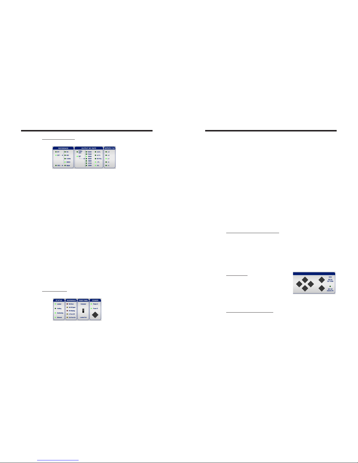
5.2. PARAMETERS LED’S
The 3 groups of LED’s left of the display indicate parameters:
- REFERENCE
The first column of led’s indicates the selected reference:
• Internal
• External
• VSO
If External has been selected, the second column of led’s indicates which
external, out of four choices:
• WC
• AES (AES-3id unbalanced)
• 10Mhz (GPS or Rubidium Clock)
• Video Sync (SD & HD).
If VSO has been selected, the second column has an ADJUST led indicating
you are currently adjusting the amount of VSO.
- OUTPUT WC RATE
Two different options are available:
• FOLLOW INPUT
• SET
The first column of LED’s indicates the option currently selected. FOLLOW
INPUT is only available when the reference is WC or AES.
With SET selected, the next two columns indicate the rate selected and the
pull coefficient(s). All standard rates are available and standard ‘pull’ coef-
ficients. These coefficients can be combined to create +4.27% and -4.096%.
- OUTPUTS 17-24
Multipliers (and dividers) are available for outputs 17-24. This means that,
if the output rate is set to 48K and x4 is selected, the frequency on outputs
17-24 will be 192K. Note that only the main frequency (48K in this case) will
be shown on the display.
5.3. STATUS LED’S
The 3 groups of LED’s right of the display indicate status:
- STATUS
• Locked: The DCD-24 PLL has achieved lock
• Holding: The reference failed and the PLL is holding the last known frequency
• Gearboxing: The generated frequency is different than the reference
For example: gen: 96K & REF: 44.1K or GEN: 48.048K & REF: 48K
• Ethernet: The DCD-24 is connected to a network via the Ethernet port.
- WARNINGS
• Ref Error: When an error occurs with the reference signal, this LED flashes.
To clear, press any key.
• Ref Off Speed: The reference is detected to be off speed by more than
1.5%.
• Ref Missing: LED comes on when no valid signal is present at the
Reference Input connector
• Termination: One of the outputs is improperly terminated. See 5.1 above
for more information.
- POWER
When the DCD-24 is on, the Power A and Power B LED’s indicate that power
is present at the corresponding connector. When the DCD-24 is turned off,
these LED’s stay off, even with power present at the connector.
Only one power supply is required to operate the DCD-24. The second input
is provided for redundancy. If two supplies are connected to the DCD-24 and
one fails, the corresponding LED flashes until the faulty supply is replaced.
When using a single power supply, either input can be used.
5.4. FRONT PANEL LOCK OUT SWITCH
When the front panel lockout switch is on, all switches except the [view] switch
are inactive (i.e. you can still check the input rate).
Note: To reset a Ref Error, you must first ‘unlock’ the front panel.
6. Navigation Keys
6.1. SET UP KEY
The Set Up mode is used to change param-
eters. To enter the Set Up mode, press the
[SET UP] key.
While in Set Up mode, the SET UP LED is on.
To exit the Set Up mode, simply press the [SET UP] key again.
6.2. UP, DOWN, LEFT, RIGHT KEYS
These keys are directly left of the [VIEW] and [SET UP] keys. They are not
labeled as such because their function is fairly obvious.
While in Set Up mode, the [UP] and [DOWN] keys are used to change the
value of the selected menu, while the [LEFT] and [RIGHT] keys are used to move
to a different menu.
DCD-24 User Manual (rev 1.00) Page 9
Page 8 DCD-24 User Manual (rev 1.00)
6.3. VIEW KEY
The [view] key is used to momentarily change the function of the display.
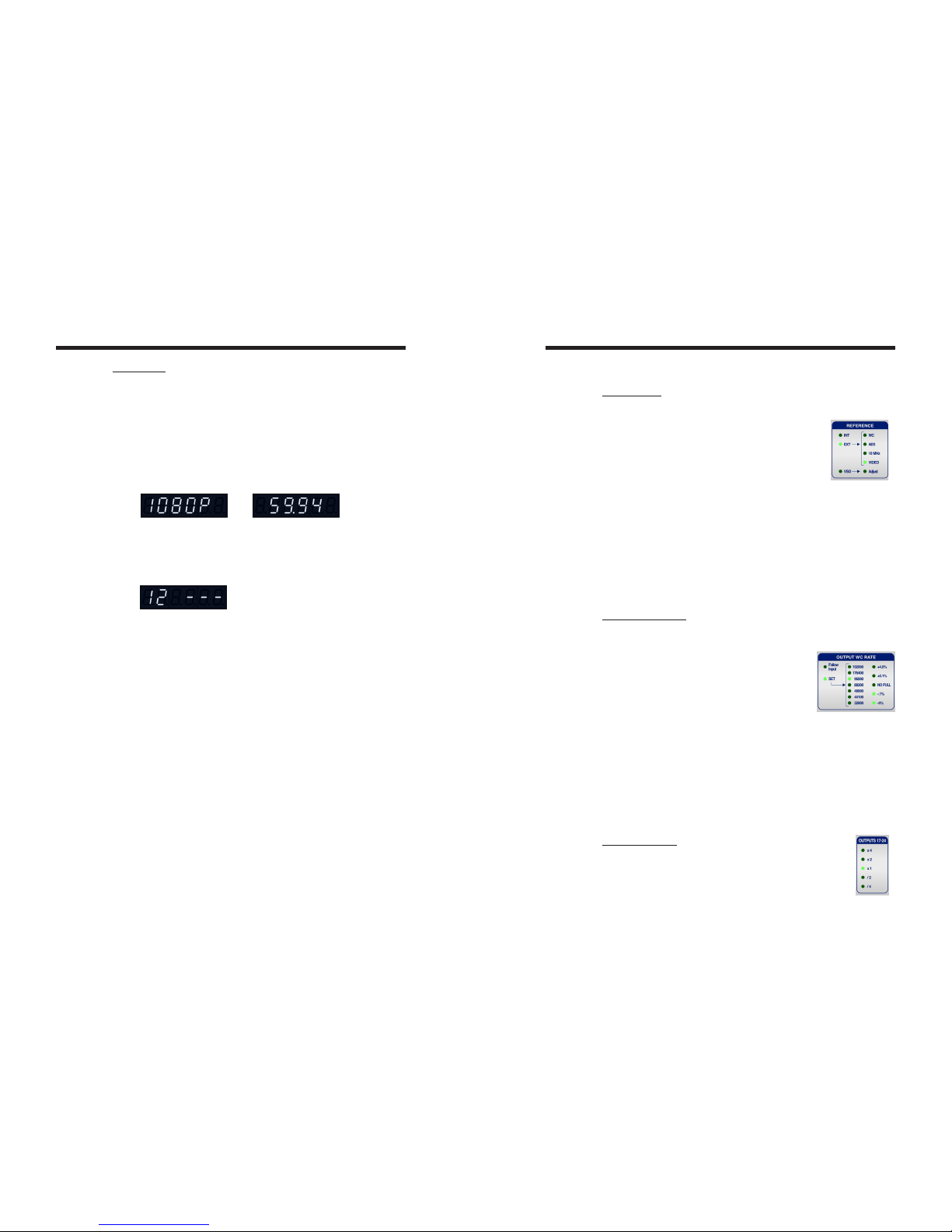
- Reference:
During normal operation, press this key to display the reference.
If the reference is WC, AES or 10MHz, the display indicates the frequency;
If the reference is INT, the display indicates “INT”;
if the reference is VSO, the display indicates the VSO amount in cents;
if the reference is Video, the display alternates between the format and the
frequency of the video ref, for example 1080p and 59.94 Hz (video formats
recognized by the DCD-24 are listed in Appendix 15.1 at the end of this
manual).
- Output Termination:
In SET UP mode, press the [view] key to display the output termination
measurements. The 2 digits on the left indicate the selected output while the 3
digits on the right indicate the measured termination in ohms. If nothing is
connected to the selected output (open), 3 dashes appear in the 3 right digits.
While holding the [view] key, press the [up] or
[down] key to change output.
7. Menu Navigation
Menus in the DCD-24 are represented by groups of LED’s. There are 3 of
them, located on the left of the display:
• REFERENCE
• OUTPUT WC RATE
• OUTPUT 17-24.
When you enter the SET UP mode, all the leds of the selected menu are on
solid and all the other parameter leds shut off for about 3/4 sec (this is done
so that you can clearly see which menu is currently selected). In the selected
menu, the current value led is flashing.
To change value, use the [up] or [down] key. Note that changes take effect
immediately.
To move to another menu, press the [LEFT] or [RIGHT] key. When pressing
the [LEFT] or [RIGHT] key, the cursor will move to the next available menu,
which may not be the adjacent menu. For example, when INT is selected as
a reference, pressing the [RIGHT] key will make the cursor ‘jump’ 2 columns
to the RATE column, skipping the EXTERNAL REFERENCE menu (we are on
INTERNAL) and the OUTPUT RATE MODE (FOLLOW INPUT is not available
with internal reference).
8. Menus Description
8.1. REFERENCE
Choices for Reference are INTERNAL, EXTERNAL and VSO.
- INTERNAL indicates that the DCD-24 is operating as
a master generator on its internal crystal;
- EXTERNAL can be one of the following:
• Word Clock
• AES (AES3id)
• 10 MHz (GPS or Rubidium clock)
• Video Sync (HD or SD - NTSC & PAL).
The external reference is connected to the rear panel universal
input connector (BNC). By selecting an input type, it is assumed
that it corresponds to the actual input signal
- VSO is selected for varispeed operations.
VSO is adjusted in cents (semitone/100). The range goes from +200
to -200 (+to - 2 whole tones), which translates to +12,2562% to
-10,9101%.
To adjust the VSO amount, press the [right] key to move to the
ADJUST menu. Then use the [up] or [down] keys, reading the
adjusted amount in cents on the display.
8.2. OUTPUT WC RATE
Two modes are available for output rate: FOLLOW INPUT and SET.
- Follow Input:
In FOLLOW INPUT mode, the input rate (the rate
of the reference) is simply transferred to the output.
In this mode, no other adjustment is required. This
mode can be used when distributing a word clock.
Note that even in this mode, the clock is always
regenerated.
FOLLOW INPUT is only available if the reference is Word Clock or AES.
- Set:
In SET mode, you must select a specific rate.
Select SET, then press the [right] key once and select one of the standard
rates, from 32KHz to 192Khz, with the [up] or [down] key.
If required, you can also apply a ‘pull’ coefficient, up or down, or a
combination of coefficients. Press the [right] key once and select the right
coefficient. The resulting frequency is indicated in the main display.
NOTE: when you change the rate, if a pull coefficient was previously set,
it is removed (‘NO PULL’).
8.3. OUTPUTS 17-24
Multipliers and dividers are available for outputs 17-24. Simply
select the one needed for your application. When x1 is selected,
the selected frequency is unaffected.
DCD-24 User Manual (rev 1.00) Page 11
Page 10 DCD-24 User Manual (rev 1.00)
13. Ethernet
The Ethernet port is used to connect the DCD-24 to a network via standard TCP/IP
protocol. It enables the user to access the DCD-24 remotely, and to upload firmware
from any computer on the network.
The first thing needed is to set its IP address properly using the front panel keys.
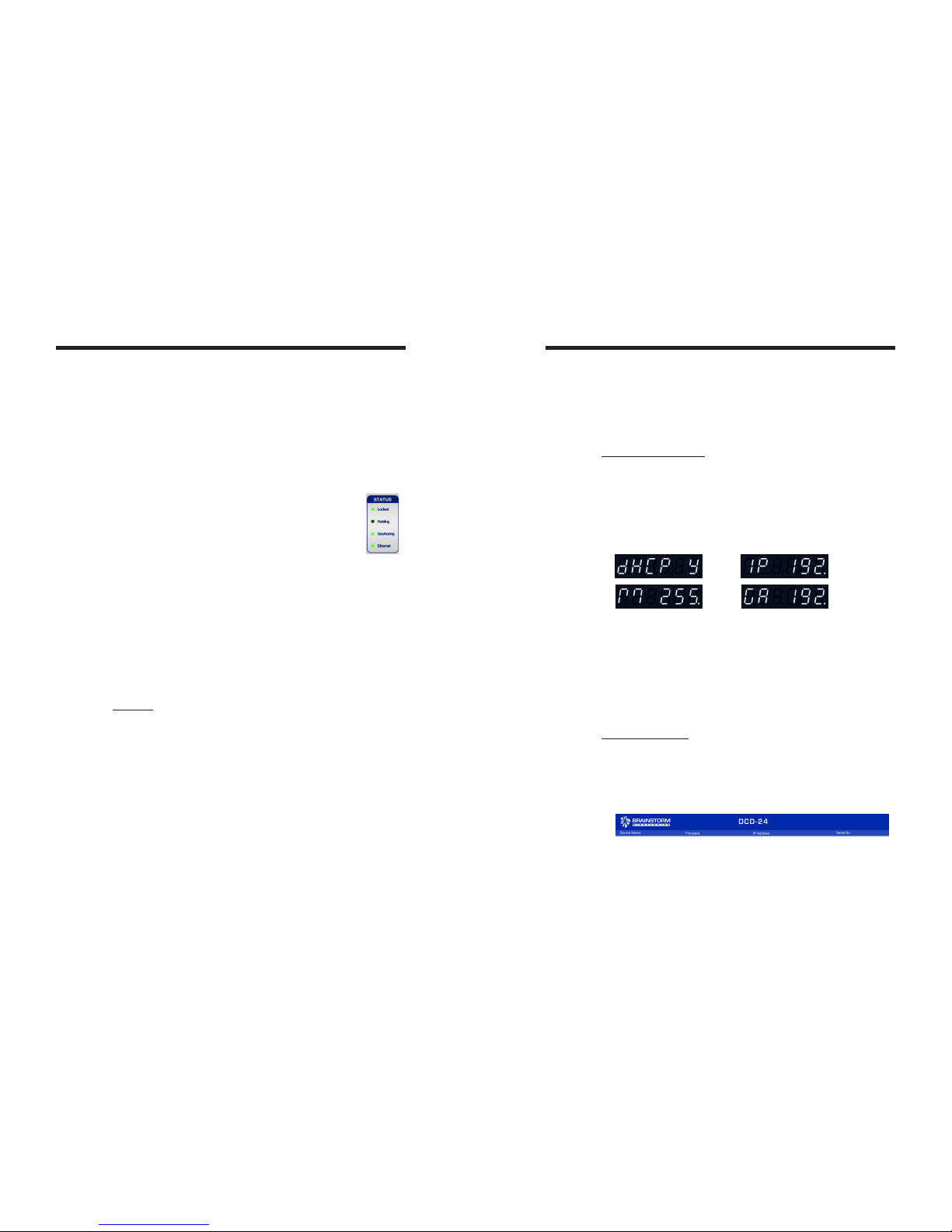
13.1. ETHERNET IP SETTINGS
The IP address setup mode is entered when you hold down the [setup] key. What
you then view on the display are portions of a long string of characters made up of
the following (default values shown):
• DHCP Y/N
• IP 192.168. 0.120
• M 255.255.255. 0
• GA 192.168. 0. 1
where “M” indicates the mask and “GA” the gateway address.
[left] and [right] keys navigate through the strings 3 digits at a time (approximately),
so all of the possible views of the above would be:
• DHCP N (or Y)
• I P 192. ↔192. 168. ↔168. 0. ↔0.120
• M 255. ↔255. 255. ↔255. 255. ↔255. 0
• GA 192. ↔192. 168. ↔168. 0. ↔0. 1
The [up] and [down] keys always control the right-most digit, which is normally flashing.
In DHCP mode (“DHCP Y”), the addresses are not adjustable, but serve to display the
values assigned by the DHCP address server.
13.2. MAIN HTML PAGE
Once your IP settings are entered properly, use any browser (Firefox, Explorer …)
and enter the IP address of your DCD-24 to display the main HTML page.
Header
The header of the HTML page includes the Serial Number, the IP Address and the
Firmware. This information comes from the unit and cannot be edited here.
Also included is the Device Name. To change it, click on the name area and a
text box will open up. Type in a new name (up to 32 characters) an hit Enter.
Or hit Esc to get out without any change.
In the upper right corner is the UPDATE FIRMWARE button. Clicking this takes
you to a separate specialized page. See chapter 14.
9. Non-Volatile Storage
The DCD-24 has non-volatile memory holding all the DCD-24 settings such as rate
and reference selection. This memory is continuously updated so that, when the
unit is turned on, it is in the same condition as it was when powered down.
NOTE: You should wait approximately 10 seconds after a change was entered
before powering down, to allow for the flash memory to be updated
10. Lock Status
The lock status of the DCD-24 is indicated in the STATUS led section:
• LOCKED Good and locked
• HOLDING Holding last known frequency after lock failure
The DCD-24 always tries to lock to its input. Once the rate has been established, if
the reference is off speed by more than 10%, it starts slewing. Note that with video,
the 10% rule applies to the horizontal frequency and not the frame rate.
While slewing, the LOCKED led is flashing. Once lock has been established, the
DCD-24 may need to adjust the phase. During the phase locking adjustment, the
LOCKED led flashes rapidly.
11. Defining the reference rate
The DCD-24 always measures the input reference and determines it’s rate.
OFF SPEED: When the reference is detected to be off speed by more than 1.5%,
the DCD-24 alerts the user by illuminating the REF OFF SPEED led in the
WARNING section. The generated frequency will track the reference and
be off by the same percentage.
12. Source Reference Failure
In the event of failure of the external reference, the DCD-24 holds the last known fre-
quency and displays “HOLDING” as a lock status.
If a signal is still present at the main reference input, the DCD-24 automatically attempts
to lock to it again. If it succeeds, it goes through the normal ‘Locked’ sequence; if not, it
continues holding and attempts to Lock to the main reference again.
If no signal is present at the main reference input, the DCD-24 will remain in
‘HOLDING’ mode indefinitely.

DCD-24 User Manual (rev 1.00) Page 13
Page 12 DCD-24 User Manual (rev 1.00)
Front Panel Replica
The main section of the HTML page is a functional replica of the front panel.
The front panel switches and web page buttons operate in parallel, although web
page clicks are inhibited while any front panel key is being pressed.
Menus are accessed by clicking on the [set up] button. In SET UP mode, a yellow
LED bar is added under the active set up column.
Unlike the front panel switch, the [view] button is click-on, click-off.
The page is refreshed every second, plus immediately after any button on the
page is clicked.
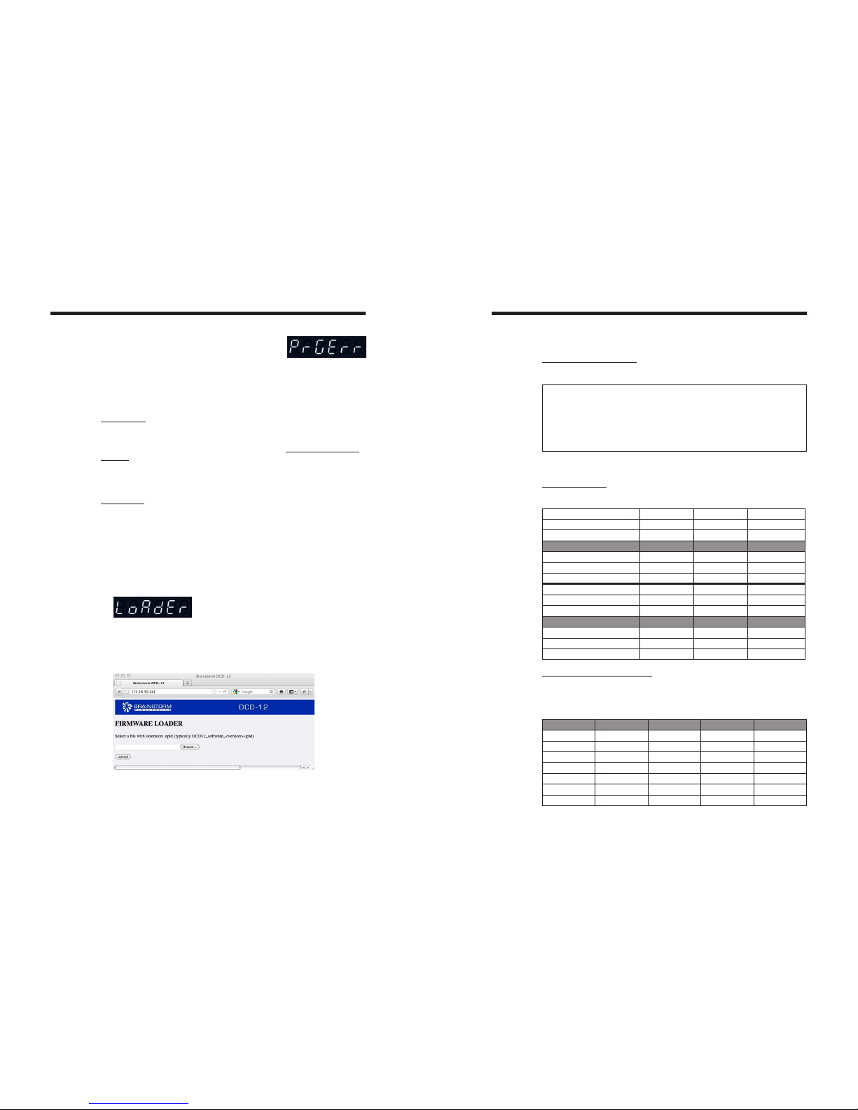
14. Firmware Updates
14.1. FIRMWARE UPDATE PAGE
Clicking on the UPDATE FIRMWARE button of the main HTML page takes you to
another page, strictly dedicated to uploading new firmware.
To update your firmware, click on the BROWSE button and select the firmware file
on your hard disk (.upld). Then click UPLOAD. The normal programming sequence
will follow.
Messages in the Upload Status box at the bottom of the page keep you informed of
the progress, including error messages.
14.2. COMPLETE VS SOFTWARE
When downloading firmware updates from the Brainstorm website, 2 types of
image files are available: ‘complete’ and ‘software’.
The DCD-24 FLASH memory is divided in several sections, for the parameters settings,
the application software, the Loader software and the FPGA image. The diagram
below shows the difference between ‘complete’ and ‘software’ updates.
The major software rev number will change whenever the FPGA or LOADER changes.
This means that:
- updates between any 1.xx version can be “software” only,
- updates from, for example, 1.xx to 2.xx must be a “complete” update.
14.3 PROGRAMMING SEQUENCE
There are 3 steps in the normal programming sequence: Upload, Verify and Program.
• Step 1: the file is uploaded. A message indicates ‘UPL’ followed by a percent-
age complete value.
• Step 2: the file is checked, indicated by a ‘TEST’ message, then ‘PASSED’.
→
• Step 3: the file is programmed into the DCD-24 flash memory. A message
indicates ‘PRG’ followed by a percentage complete value.
Note: During the 3rd step (programming), Ethernet is internally disconnected.
Reboot
• At the conclusion of a Flash programming sequence following the upload of
a ‘complete’ image file, the display slow flashes “REBOOT” to indicate that a
reboot is required. Turn power off then back on.
• After uploading a ‘software’ image file, the DCD-24 automatically reboots.
14.4 PROGRAMMING ERRORS
A. Upload Error
An error during the upload step should always be
recoverable since the programming hasn’t started
yet. Simply start the Upload again.
DCD-24 User Manual (rev 1.00) Page 15
Page 14 DCD-24 User Manual (rev 1.00)
15. Appendix
15.1 VIDEO INPUT FORMATS
The following table lists all the video formats recognized by the DCD-24 as reference:
525i/29.97 NTSC
625i/25 PAL
720p/50
720p/59.94
720p/60
1080i/25
1080i/25 295M
1080i/29.97
1080i/30
1080sF/23.976
1080sF/24
1080sF/25
1080sF/29.97
1080sF/30
1080p/23.976
1080p/24
1080p/25
1080p/29.97
1080p/30
1080p/50
1080p/50 295M
1080p/59.94
1080p/60
Not supported are the low frame rate 720p formats.
15.2. PULLED RATES
Here is a list of the standard and pulled rates generated by the DCD-24.
-4.096%
(25 to 23.976 f/s)
42,294 84,587 169,175
-4.0%
(25 to 24 f/s)
42,336 84,672 169,344
-0.1%
(30 to 29.97 f/s)
44,056 88,112 176,224
BASE RATE 44,100 88,200 176,400
+0.1%
(29.97 to 30 f/s)
44,144 88,288 176, 576
+4.166%
(24 to 25 f/s)
45,938 91,875 183,750
+4.2709%
(23.976 to 25 f/s)
45,983 91,967 183,934
-4.096%
(25 to 23.976 f/s)
46,034 92,068 184,136
-4.0%
(25 to 24 f/s)
46,080 92,160 184,320
-0.1%
(30 to 29.97 f/s)
47,952 95,904 191,808
BASE RATE 48,000 96,000 192,000
+0.1%
(29.97 to 30 f/s)
48,048 96,096 192,192
+4.166%
(24 to 25 f/s)
50,000 100,000 200,000
+4.2709%
(23.976 to 25 f/s)
50,050 100,100 200,200
15.3. MULTIPLIER/DIVIDER RATES
Through WC outputs 9-12, the DCD-24 can apply a multiplier or a divider to the
selected base frequency. Here is a list of the available rates. An ‘X’ indicates this
choice is not available.
FSx2 FSx4 FS/2 FS/4
192.0 KHz X X 96.0KHz 48.0KHz
176.4 KHz X X 88.2KHz 44.1KHz
96.0 KHz 192.0KHz X48.0KHz X
88.2 KHz 176.4KHz X44.1KHz X
48.0 KHz 96.0KHz 192.0KHz X X
44.1 KHz 88.2KHz 176.4KHz X X
32.0 KHz 64.0KHz 128.0KHz X X
B. Programming Error
If an error occurs during the programming step, the
consequences will depend on the type of update:
- SOFTWARE UPDATE: The Application Software is probably corrupted but the
Loader is intact and can be used to restore the DCD-24 (see 14.5).
- COMPLETE UPDATE: A Programming error during a ‘complete’ update is most
likely not recoverable via Ethernet and your DCD-24 will need to be returned to
the factory for a full restore of its flash memory.
IMPORTANT:
IF A PROGRAMMING ERROR OCCURED DURING A ‘COMPLETE’
UPDATE AND THE UNIT IS STILL ON, TRY RUNNING THE PROGRAM-
MING SEQUENCE AGAIN AS DESCRIBED IN 14.2, WITHOUT CYCLING
POWER.
IF POWER IS TURNED OFF, THE UNIT WILL MOST LIKELY NEED TO BE
RETURNED TO THE FACTORY.
14.5 LOADER
The Loader is a fall-back web page that allows you to restore your DCD-24 in case
of programming failure. This page is located in a different area of the Flash Memo-
ry (see LOADER SOFTWARE on the Flash Memory map above, 14.2).
To enter the LOADER mode:
Hold down the [down] and [setup] keys while powering up and until “DCD-24”
appears on the display (you don’t have to hold down the power key itself -- a single
hit is sufficient).
The unit will next display “Loader” instead of the usual software version number.
From Loader mode the IP addresses and DHCP mode can be adjusted in the usual
way. Then, simply point your browser to the IP address of your DCD-24.
The LOADER page is similar to the regular Upload page described above, without
active status updates.
To restore your unit, use the BROWSE button to locate the firmware file on your
hard disk (.upld) and click UPLOAD. The normal programming sequence described
in 14.3 will follow. Either “software” or “complete” files can be uploaded this way.
Page 16 DCD-24 User Manual (rev 1.00)
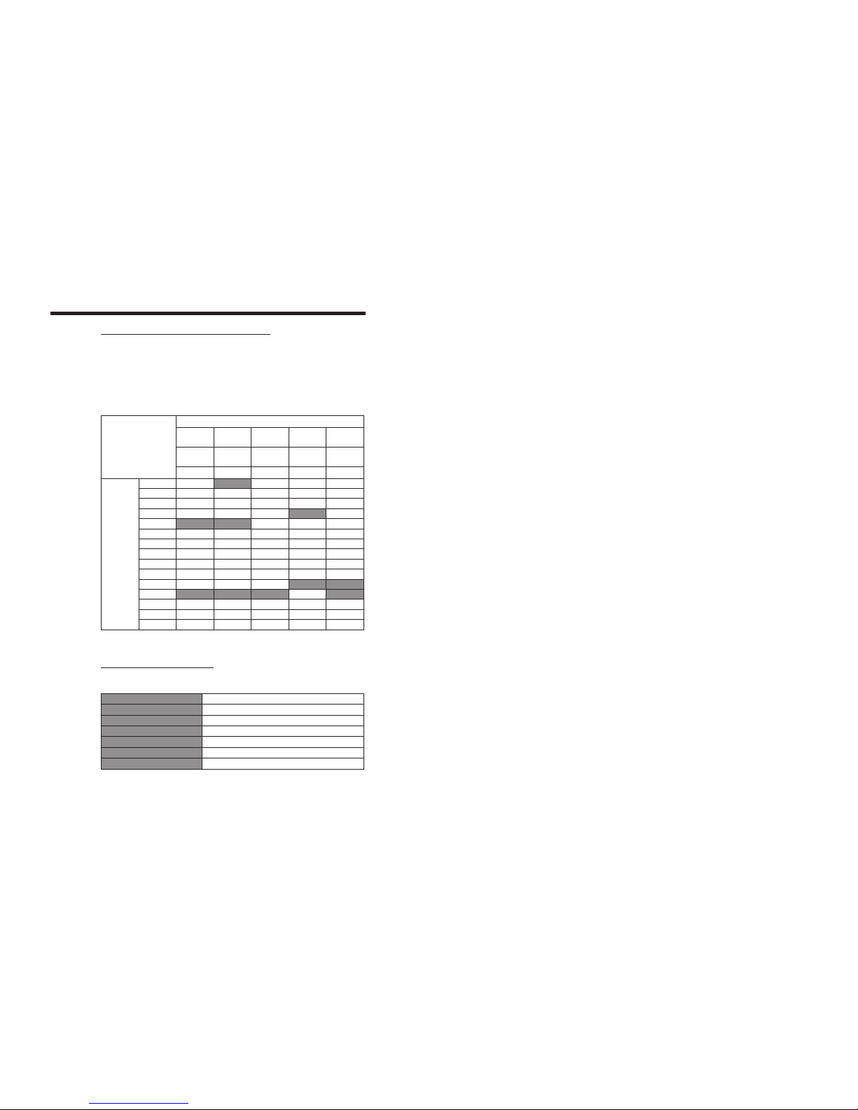
15.4. WORD CLOCK PHASE ALIGNMENT TO VIDEO
Whenever mathematically possible, the DCD-24 will achieve accurate alignment
between the vertical sync of the incoming video and the rising edge of the output
wordclock. Accuracy is per the original AES requirement of 5% of the sample
clock period. This phase adjustment begins immediately after intial lock has been
achieved. Please allow up to 30 seconds for this state to be realized.
The table below indicates when alignment will occur between the input video “refer-
ence point” (vertical sync) and the output wordclock rising edge.
Video Input Types and Rates
PAL Slow PAL
24
NTSC Slow PAL
23.976
HD 30
HD 60
HD 25
HD 50 HD 24
HD 29.97
HD 59.94 HD 23.976
30.000 25.000 24.000 29.970 23.976
DCD-24
WC
Output
Rates
32000.000
Y
42293.706
42336.000
44055.944
Y
44100.000
Y Y
44144.100
45937.500
45983.438
46033.966
46080.000
47952.048
Y Y
48000.000
Y Y Y Y
48048.000
50000.000
50050.000
NOTES: All outputs are rate locked at all times.
15.5. FACTORY DEFAULT SETTINGS
The following are the factory default settings.
REFERENCE WC
OUTPUT RATE 48KHz
OUTPUTS 9-12 X1
DHCP No
IP ADDRESS 192.168.0.120
SUBNET MASK 255.255.255.0
GATEWAY 192.168.0.1
BRAINSTORM ELECTRONICS, INC.
www.brainstormtime.com
Distributed Exclusively by
plus24
8974 Kramerwood Place, Los Angeles, CA 90034 - USA
Tel: (323) 845-1171 - Fax: (323) 845-1170
www.plus24.net
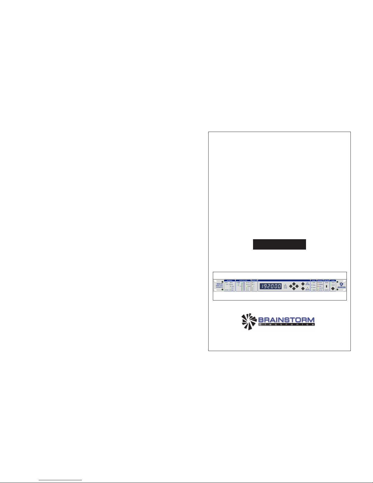
DCD-24
Word Clock
Distributor
Operation Manual
Software version 1.00
Table of contents
Popular Media Converter manuals by other brands

Cypress
Cypress CM-398DI Operation manual

Nikon
Nikon AF-S TC-20E III user manual

Microchip Technology
Microchip Technology dsPIC33F Family Reference manual

Baumer
Baumer HUBNER BERLIN HOGS 71 Mounting and operating instructions

Techlogix
Techlogix TL-C-HDCP user manual

M-system
M-system M8TS instruction manual


