Onbon OVP-H4D User manual

USER MANUAL
OVP-H4D
Version:V1.1 Date:2019.7.23

www.onbonbx.com 第 2页
Statement
Any companies or privates cannot copy, transcribe or translate part or
whole content of this file without our written permission. And cannot use it on
any business or benefit filed with any forms.
The specifications and information which are mentioned on the file is
for reference only, if there’s update, we will not inform you. This file is only
for guidance, and all information will not be for any promises.

www.onbonbx.com 第 3页
Directory
Statement................................................................................................................... 2
Directory......................................................................................................................3
Instruction................................................................................................................... 5
Safety notification................................................................................................5
Functions.................................................................................................................... 6
Description........................................................................................................... 6
Features................................................................................................................6
PANEL.........................................................................................................................7
Front panel........................................................................................................... 7
Basic steps................................................................................................................. 9
Menu............................................................................................................................9
Menu button operation....................................................................................... 9
The initial state of the main interface.............................................................10
Main menu..........................................................................................................10
Splice mode....................................................................................................... 12
LED screen parameters...................................................................................14
Layout..................................................................................................................16

www.onbonbx.com 第 4页
Image quality......................................................................................................18
Crop menu..........................................................................................................19
Option..................................................................................................................20
USER SAVE AND LOAD MODE..........................................................................24
User save mode................................................................................................ 24
User mode switch............................................................................................. 25
MODE..................................................................................................................26
FAST MODE...................................................................................................... 26
Intelligent guiding.................................................................................................... 27
FAQ............................................................................................................................28
Technical parameters............................................................................................. 30

www.onbonbx.com 第 5页
Instruction
Safety notification
There are high voltages in this product. Non-professional maintenance
personnel are not allowed to open the case or repair the device by
themselves to avoid danger.The input voltage range of this product's AC
power supply is 100 ~ 240V, 50/60Hz, please use the correct power supply.
This product is grounded through the power cord. In order to avoid
current impact, please insert the power cord into the grounded socket
before connecting the product input or output port. Protective grounding of
the grounding conductor in the power cord is essential for safe
operation.Before performing any hardware operations, please turn off the
power of the LED video processor and discharge static electricity on your
body by touching a grounded surface.When you want to connect or
disconnect any signal cable or control cable, please make sure that all
power cables have been unplugged in advance.
Please use it in a clean, dry and ventilated environment. Do not put
this product in high temperature and humidity environments.This product is
an electronic product, please keep away from fire, water and flammable
and explosive dangerous goods.If you find unusual conditions such as
strange noises, smoke or odors, you should immediately unplug the power
cord and contact your dealer.

www.onbonbx.com 第 6页
Functions
Description
OVP-H4D is a hing-end video processor which is used for big LED
screen, stage, rent, meeting room and so on. This product adopts 4K
image and splicing technology which is used for small spacing LED screen.
Which gives promise for the consistency and synchronization of splicing.
For high resolution LED screen, users can input and output point to point
as to get a better effect.
Features
Maximum resolution is 5.1 million pixels, the horizontal
maximum8000 pixels, vertical maximum 3840 pixels;
Fast seamless switching between all input signal sources and
output modes;
With 7 channels of ultra high definition (UHD) digital and analog
input interface;
Dedicated DVI monitoring output interface, support local window
output monitoring;
Support 6 channels digital input port DVI\HDMI customized input
resolution settings;
Support input signal source hot backup;
8 user modes can be pre-stored, and can be fast invoked by users;
Support intelligent navigation function;
Support two splicing methods on output port: Horizontal and
Vertical;
Support local USB2.0 multi-media player;
The device can be controlled by panel keys, LAN, USB and Mobile
APP

www.onbonbx.com 第 7页
PANEL
Front panel

www.onbonbx.com 第 8页

www.onbonbx.com 第 9页
Basic steps
Click [OK] to enter the main menu interface, and then follow the steps
below to set the controller:
The first step: Set LED screen parameters (width, height, network port
width and height and start) according to the size of the LED screen;
Step 2: Select the corresponding signal source according to the signal
source required by the user;
Step 3: If necessary, make appropriate adjustments to the "display
window";
Step 4: Select "Mode Save" or press the [SAVE] key to enter the
"Mode Save" menu to save the current display mode for next recall
Note: For detailed instructions on the above four steps, please refer to
the next chapter "Introduction to Main Menu".
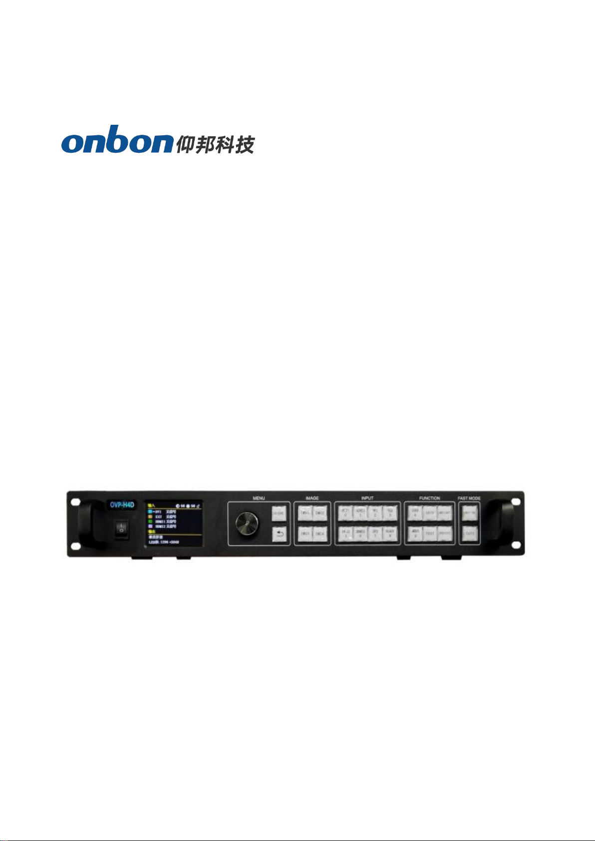
Menu
Menu button operation
The key operation area related to the menu is the MENU area,
including a knob, a confirmation key [OK], a return key [] and a [GUIDE]
key.
In the initial state of the system, short press [OK] to enter the main
menu setting interface. When the return key is pressed, the menu system
will return to the previous menu in order until it returns to the initial state
.In the browsing state, turn [Knob] counterclockwise to move the
cursor upward or left; turn [Knob] clockwise to move the cursor downward
or right. When the cursor is moved to the item to be adjusted, press the
[OK] key to enter the corresponding setting sub-menu. At this time, turn the
[knob] counterclockwise to decrease the current parameter value; turn the

www.onbonbx.com 第 10 页
[knob] clockwise to Increase the current parameter value. If the adjustment
is completed, short press [OK] to write the data and save it. To return to the
previous menu, use the return key; until you return to the initial state. Press
【GUIDE】key to quickly switch out the "smart navigation" setting interface.
Note: The [knob] cannot be turned too fast, otherwise the value
adjustment will change very little and should be rotated at a constant
speed.
The initial state of the main interface
During the system start up, the LCD screen will display the startup
interface. After the startup is complete, the current machine status will be
displayed on the screen. The initial menu of the system startup is shown in
the following figure:
There are 3 areas:
Input:It displays the input source selection information of the four
screens. If a screen is not open, it displays "Not Open"; Screen 1 is
always open regardless of the situation;
Output:Shows real LED screen size which is set by users;
Top right corner:Shows present contrast, brightness values and
button lock status
Main menu
This equipment adopts 2.8”LCD screen (320*240), and adopts font 24*24

www.onbonbx.com 第 11 页
which can display 10 rows. There are 6 parts on menu. If you are not in
menu status, please click【OK】,it will show:
Main menu and branch menu:
Main menu
The second and third menu
Splice
mode
Vertical splice:maximum 4000, vertical maximum 3840
Horizontal splice:maximum 8000, vertical maximum 2000
LAYOUT
Picture 1 (horizontal width, vertical height, horizontal start,
vertical start) is always on
.Picture 2 (picture switch, horizontal width, vertical height,
horizontal start, vertical start)
Picture 3 (picture switch, horizontal width, vertical height,
horizontal start, vertical start)
Picture 4 (picture switch, horizontal width, vertical height,
horizontal start, vertical start)

www.onbonbx.com 第 12 页
LED
Setting
Total width, total heightOUT1-OUT2: horizontal width,
vertical height, horizontal start, vertical start
Image
quality
Brightness,contrast,saturation,sharpness,color temperature
and dynamic contrast.
Crop
Switch, crop width, crop height, crop horizontal start, crop
vertical start
Save
mode
Mode 1-Mode 8
Load
mode
Mode 1-Mode 8
Option
Input EDID (horizontal width,vertical width,refresh rate) Input
hot spare (close, backup for input source)
VGA setting (adjust automatically,horizontal start,vertical
start) Planned tax(tax 1, tax 2...)
Other setting(switch stunt, voice setting) Testing
photo(close, photo 1 to photo 8)
key lock(open, close)
Factory reset(ADC calibration,languages,factory
reset,firmware version)
Splice mode
The system provides two splicing methods for users to choose. As
mentioned above, you need to select the “splicing method” according to the
LED screen width and height ratio and the use scenario. "
It is more suitable; when the shape of the LED screen is a long screen,
it is more appropriate to choose "horizontal stitching". When selecting the
splicing method, you should also pay attention to whether the "LED screen
can set the maximum number of points" displayed in the prompt
information bar meets the actual LED screen width and height
requirements.
After clicking the 【OK】button, it will be confirmed. At this time, the
system will automatically jump to the “LED screen parameter” setting
menu.
Horizontal splice
In the non-menu state, click the [OK] button to enter the main menu,

www.onbonbx.com 第 13 页
then select "splicing mode", and then select "horizontal splicing" to pop up
the following menu:
After clicking the "OK" button, it will be confirmed. At this time, the
system will automatically jump to the "LED screen parameter" setting menu,
and the user needs to continue to complete the relevant parameter settings.
In the horizontal splicing mode, the four DVI output ports OUT1~OUT2 of
the splicer are arranged in a horizontal direction. At this time, the LED
screen can be set to a maximum number of points: 8000 in the horizontal
direction and 2000 in the vertical direction, and the total number of points
cannot exceed 5.1 million points. For details, see The setting instructions of
"LED screen parameter" will follow. This splicing method is more suitable
for the screen with long shape.
Vertical splice
In the non-menu state, click the [OK] button to enter the main menu, and
then select "stitching method", then select "vertical stitching" will pop up the
following menu:
After clicking the "OK" button, it will be confirmed. At this time, the system
will automatically jump to the "LED screen parameter" setting menu, and
the user needs to continue to complete the relevant parameter settings. In
the vertical splicing mode, the four DVI output ports OUT1~OUT2 of the
splicer are arranged in a vertical direction. At this time, the LED screen can
be set to a maximum number of points: 4000 (horizontal), 3840 (vertical),

www.onbonbx.com 第 14 页
and the total number of points cannot exceed 5 million For details, please
refer to the setting instructions of "LED screen parameter" below. The
splicing method is more suitable for the ultra-high-definition LED large
screen in the shape of a vertical bar.
LED screen parameters
LED size
Click【OK】as to enter into main menu, then choose “LED setting”, as
below:

www.onbonbx.com 第 15 页
After the LED screen parameters are set, move the cursor to [OK] and
press the [OK] key to save the data. If the "splicing method" is changed
before the LED screen parameters are set or the LED screen width
parameter crosses the boundary under horizontal splicing The system will
be in the reset state, users need to wait patiently for the system to reset.
Pay attention to the value range of the LED screen size and the total load
points of the LED screen:
Horizontal splice
(1)When the total width of the LED screen <= 4096
LED screen total height <= 2000;
Value range of OUT1~OUT2 output port:Width 0~4000, height 0~2000
Note: When the width and height of an output port in OUT1~OUT4 is 0,
it means that the output port has no output.
(2)When 4096 <total width of LED screen <= 8000
The total height of the LED screen: It is determined by the
maximum number of points that the LED screen can carry (5.1 million
points).
The system will automatically limit when setting.
Value range of OUT1~OUT2 output port:Width: 0~4000, height: the same
as the total height of the set LED screen
Note: When the width and height of an output port in OUT1~OUT2 is 0, it
means that the output port has no output.
Vertical splice

www.onbonbx.com 第 16 页
LED screen total width <= 4000
LED screen total height <= 3840
And the total number of points on the LED screen can not exceed 5 million
points.Value range of OUT1~OUT4 output port:Width 0~4000, height
0~2000
Note: When the width and height of an output port in OUT1~OUT2 is 0, it
means that the output port has no output.
Layout
Pls go to the layout image by press OK when at the status of non-menu.
Horizontal width: the adjustment range is 120 ~ the maximum number of
points can be set in the horizontal direction.
Vertical height: the adjustment range is 68 ~ the maximum number of
points can be set in the vertical direction.
Horizontal start: The minimum value is 0, and the maximum value is the
maximum number of horizontal points minus the horizontal width.
Vertical start: The minimum value is 0, and the maximum value is the
maximum number of vertical points minus the vertical height
note:
(1) Up to 4 screen display windows can be opened in each splicing mode,
and the screen 1 window is always open
(2) When two or more screens are open, if the screens overlap, it may
cause display confusion;
(3) Click the "MODE" shortcut key on the front panel to enter the system
"fixed mode call" menu, you can quickly open the desired screen display
window.
(4) The picture display window can float arbitrarily between each DVI
output window OUT1~OUT2 without its boundary.
(5) The screen display window opened outside the size mapping range of
the LED screen can be used as the input source monitoring window.
1. LAN OUTPUT SETING
In the non-menu state, click the [OK] button to enter the main menu,

www.onbonbx.com 第 17 页
then select "Output Settings", and then select "Network Port Output
Settings" to enter the network port output settings menu:
note:
(1) As mentioned above, when the "accept card connection" setting of
each LED screen's network port is completed through the PC control
software, the LED screen size and so on will be automatically calculated
and updated to the controller synchronously, so generally no need to set
the LED screen parameters Including the size of the LED screen and the
parameters of each network port)
(2) When you need to "arbitrarily splice" or set for each network port,
please pay attention to the value range and the number of loaded points of
a single network port width and height
:Horizontal width: 256~4000
Vertical height: 128~3840
Horizontal width x vertical height <= 655360 (when width> height)
Horizontal width x vertical height <= 652738 (when width <height)
Image size
Click ok then go to output setup ,then select the image size adjust:

www.onbonbx.com 第 18 页
Note:
Regardless of whether the input image ratio is 4:3 or 16:9, the output
image is displayed by "full screen" by default, so in some cases it will cause
equal proportion distortion of people, at this time, you can change the width
and height of the image through "display window adjustment" ratio.
2. Pixel to pixel
In the non-menu state, click the [OK] button to enter the main menu, then
select "Output Settings", and then select "Point-to-point output" to enter the
point-to-point output menu.The default state of point-to-point output is off.
When the point-to-point output is in the "on" state, the input signal is
directly output to the output without any processing by the processor, that
is, the output image and the input image are completely point-to-point.
note:
(1) When the point-to-point output is in the "on" state, the controller
outputs the input image to the large LED screen without any scaling at this
time.Therefore, it is very convenient to debug the LED screen module (plot
point display, etc.);
(2) The point-to-point output is only valid in the range of 3840*2160;
(3) When the input resolution is set to the same size as the LED through
the "Advanced Options-Input Resolution" menu, the image can be
displayed without any scaling, so the best display effect can be achieved.
(4) When the point-to-point output is turned on, the image capture will be
automatically turned off.
Image quality
Click【OK】as to enter into main menu--”IMAGE QUALITY”, as below:

www.onbonbx.com 第 19 页
Brightness: adjust range 0-100, default is 50.
Contrast: adjust range 0-100, default is 50.
Saturation: adjust range 0-100, default is 50.
Sharpness: adjust range 0-10, default is 5.
Dynamic contrast: adjust range 0-4, default is 1. 0 means closed, it’s
invalid for inputting VGA signal source.
Color temperature: “warm”, “natural”, “cold”, “custom”.
Customized color temperature:adjusting range in RED 0-100
adjusting range in BLUE 0-100 adjusting range in GREEN 0-100
Note:You can also adjust brightness by “BRIGHT”button on board
Crop menu
Click【OK】as to enter into main menu--”CROP”, as below:

www.onbonbx.com 第 20 页
Minimum is 128, maximum is “width of input signal”.
Minimum is 128, maximum is “height of input signal”.
Minimum is 0, maximum is “width of input signal”- “height of input
signal”.
Minimum is 0, maximum is “height of input signal”- “width of input
signal”.
Note: (1)Crop is for input source, so crop width and height cannot bigger
than the resolution of present cropped signal source.
(2)Users can select different input source by input source button on
boar
Option
Click【OK】as to enter into main menu--”OPTION”, as below:
1. Input EDID
It offers EDID editing function of DVI/HDMI input signal source, means, the
recommended resolution of input signal source. In WIN7 system, when the
“input EDID (recommended)” is modified which is read by PC, the output
resolution of PC will be modified too;But for WIN10 system, output
resolution of PC won’t be changed, users need to operate manually.
By setting the input resolution, the user can realize the input and output of
Table of contents
Other Onbon Media Converter manuals