Brainstorm DCD-8 User manual
n
Word Clock
ÃÌÀ«>ÞâiÀ
ÊÃÌÀLÕÌÀ]Ê>Ê-ÌÀ««iÀÊ>`Ê>Ê>ÞâiÀ
Operation Manual
Software version 2.3.0
...Intelligent Solutions For The Recording Studio

DCD#8
Word)Clock)Distripalyzer)
Owner’s)manual
Version(2.30
August(2010
All(materials(herein(©(Brainstorm(Electronics,(Inc.
Brainstorm(Electronics(reserves(the(right(to(change(or(modify(the(contents(
of(this(manual(at(any(time.
Credits
Concept:(AID,(Brainstorm(Electronics
Software:(Gerry(Lester
Manual:(Bernard(Frings,(Gerry(Lester,(Janice
Technical(Assistance:(Jim(Pace,(Jeff(Evans
Brainstorm)Electronics,)Inc.
www.brainstormtime.com

Page 2 DCD-8 User Manual
Table of contents
1. INTRODUCTION ...................................................3
2. I/O’S DESCRIPTION AND CABLE REQUIREMENTS .........................4
3. INSTALLATION ....................................................5
4. QUICK START .....................................................5
5. FRONT PANEL DISPLAY & LED’S .......................................6
6. NAVIGATION KEYS ................................................7
7. MENU NAVIGATION ...............................................8
8. MENUSDESCRIPTION ..............................................9
01- Rate A ...................................................9
02- Reference A ...............................................9
03- Alternate Reference ........................................10
04- Word Clock Out ..........................................10
05- Audio Out ...............................................10
06- Audio In A ..............................................10
07- Audio In B ...............................................11
13- Alt Ref Auto Relock ....................................... 11
21- Rate B ..................................................11
22- Reference B ..............................................11
31- Optical I/O ..............................................12
33- AES Input Default Clock Source................................12
41- Input Status ..............................................12
42- Termination...............................................12
51- Video Option (menus 51-59 reserved for VSG-4 option card) .........12
91- Menu Lockout ............................................13
92- Settings .................................................13
93- Names ..................................................13
99- DCD-8 Software version & FW Serial No ........................14
9. NON-VOLATILE STORAGE ..........................................14
10. LOCK STATUS...................................................14
11. DEFINING THE RATE: Set, Auto & Learn................................15
12. VSO ......................................................... 16
13. SOURCE REFERENCE FAILURE OPTIONS...............................17
14. AUDIO ROUTING ................................................19
15. FIREWIRE.......................................................20
16. UPDATING THE DCD-8 FIRMWARE ...................................21
17. REF B - Main Display ..............................................22
18. APPENDIX .....................................................22
Pulled Rates .................................................22
Multiplier Rates ...............................................23
Error Messages ...............................................23
Digital Audio Formats .........................................25
Word Clock phase alignment to Video ............................ 26
Video Input Formats .......................................... 26
Factory Default Settings ........................................27
19. OPTION CARDSFOR THE DCD-8 ....................................27
20. USER’S SETTINGS................................................28

DCD-8 User Manual Page 3
1. Introduction
Congratulations on purchasing the DCD-8 Word Clock Distripalyzer. In the tradition
of the Brainstorm Distripalyzers, the DCD-8 is a Word Clock distributor, striper and
analyzer.
Bglb]^ma^=<=&1blZo^kr_e^qb[e^`^g^kZmhkpbmanemkZehp&cbmm^k'PbmabmlfZgrB(Hlma^
=<=&1blZ\hfie^m^phk]\eh\dlhenmbhg'BmlfZbg_^Zmnk^lbg\en]^3
Phk]\eh\d`^g^kZmhk
Phk]\eh\d^qmkZ\mhk
Phk]\eh\d]blmkb[nmhk
Phk]\eh\dZgZers^k
?hkfZm\hgo^km^k
=b`bmZe:n]bhkhnm^k
Ob]^hLrg\@^g^kZmhk!himbhgZe"
1.1. SYSTEM ARCHITECTURE
The DCD-8 generator has 2 domains, A& B, each capable of generating a differ-
ent rate. Any rate can be generated, up to 192KHz.
The DCD-8 can be referenced to any of the inputs: WC, AES, S/PDIF, Optical,
video or internal crystal.
The A and the B rates can be assigned to any word clock BNC output and audio
output, as silent audio.
In addition, each domain can re-clock any audio input and route it to any audio output.
AUDIO OUTPUTS
REFERENCE SELECTOR
WC GENERATOR
“A” DOMAIN
Rate selection
WC GENERATOR
“B” DOMAIN
Rate selection
BNC OUT 1&2 BNC OUT 3&4 BNC OUT 5&6 BNC OUT 7&8
MULTIPLIER
Domain Select
AES/EBU OUT S/PDIF OUT ADAT OUT 1394
Domain Select Domain Select Domain Select
WORD CLOCK OUTPUTS
AUDIO INPUT SELECTOR
AUDIO RECLOCKING
“A” Domain
AUDIO RECLOCKING
“B” Domain
Source Select Source Select Insert Select
WC 1
WC 2
WC 3
AES 1
AES 2
AES 3
S/PDIF
OPTICAL
VIDEO
INTERNAL
AES 1
AES 2
AES 3
S/PDIF
1394
OPTICAL

Page 4 DCD-8 User Manual
2. I/O’s Description and Cable Requirements
1 2 3 4 5 6 7 8 9 10
1. POWER
The DCD-8 requires 12VDC @ 25W. Acceptable
voltage range is 12VDC +/-15%.
The external power supply provided with the DCD-8
can accept 100 to 240 VAC input at 50 - 60 Hz so
it is suitable for use anywhere in the world.
➢Use the standard IEC power cable supplied.
2. 1394
This IEEE 1394 I/O is used to send /receive digital
audio to /from a FireWire device and to update
the DCD-8 firmware.
➢Use standard 6-pin FireWire 400 cables.
3. OPTICAL
Optical transmitter & receiver - this I/O accepts
ADAT or S/PDIF optical audio signals. See menu
31 for selecting the appropriate format.
➢Use standard optical fiber cables.
4. S/PDIF
2 RCA connectors - I/O. transformer isolated
Used for coaxial S/PDIF.
➢Use standard 751RCAcoaxial cables.
5. AES/EBU IN
2 XLR female connectors - Transformer isolated bal-
anced inputs; accepts AES3 or AES11.
➢Use standard 3-conductor shielded 1101XLR
cables.
6. AES/EBU OUT
2 XLR male connectors - Transformer isolated bal-
anced outputs for AES3 or AES11.
➢Use standard 3-conductor shielded 1101XLR
cables.
7. VIDEO REF (IN & LOOP)
2 BNC connectors - Input & Loop through
Accepts NTSC, PAL or HD analog reference signal
IMPORTANT NOTES:
UÊ/ÃÊ«ÕÌÊÃÊÕÌiÀ>Ìi`°ÊvÊÌiÊnÊÃÊÌiÊ
last item in the chain, it needs to be terminated by
placing a 751terminator on the loop BNC.
UÊvÊÌiÊÛ`iÊÀiviÀiViÊÃÊÊ>>}ÊÃ}>]ÊÜiÊÀiV-
ommend NOT DAISY-CHAINING IT.
➢Use a standard 751video cable.
8. WORD CLOCKIN
2 BNC connectors - Transformer isolated WC inputs
- also accepts 10MHz GPS
Internally AC coupled and terminated, 751.
➢Use standard 751coaxial BNC cables.
9. WORD CLOCKOUT
8 BNC connectors - WC outputs grouped in 4
pairs: 1&2, 3&4, 5&6, 7&8.
➢Use standard 751coaxial BNC cables.
10. VIDEO SYNC GEN OUT (Optional)
For info, see the VSG-4 Video Sync Generator’s
manual.
1211
11. WORD CLOCKINPUT 3 - FRONT PANEL
1 BNC connector - transformer isolated
This connector is identical to the other 2 WC inputs
on the rear panel.
➢Use a standard 751coaxial BNC cable.
12. AES/EBU INPUT 3 - FRONT PANEL
1 BNC connector - transformer isolated
This front panel BNC accepts unbalanced AES/EBU
input (AES3id).
➢Use a standard 751coaxial BNC cable.

DCD-8 User Manual Page 5
3. Installation
3.1. UNPACKING
When unpacking the DCD-8 the following items should be in the shipping carton:
UÊ nÊÕÌ
UÊ 1ÛiÀÃ>Ê*ÜiÀÊ-Õ««ÞÊ£Ó6ÊJÊÓxÜ®
UÊ Ê«ÜiÀÊV>Li
UÊ "ÜiÀ½ÃÊ>Õ>ÊEÊ,i}ÃÌÀ>ÌÊV>À`
3.2. INSTALLING THE DCD-8
The DCD-8 is designed to be mounted in a standard 19” rack. It requires 1U in height.
Ideally, it should be located near your AD/DAand in the same rack.
Usual precautions should be respected when wiring the DCD-8: use high quality cables with
good shield to guarantee a good signal transmission. Keep your cables as short as possible.
Devices connected to the DCD-8’s WC outputs need to be terminated. If no termination is pro-
vided on the device, use a BNC-T with a 751termination. If multiple devices are connected to
a single DCD-8 WC output, only the last device in the chain should be terminated. However,
to preserve the integrity of the transmission line, it is recommended that you do not daisy-
chain word clock outputs as it can significantly degrade signal quality.
4. Quick Start
The DCD-8 is extremely versatile and can accommodate many different situations. You
should read this manual to familiarize yourself with its many features. The following
simple steps are only provided to get you started right away.
Connect the power supply provided with the DCD-8 to the 4 pin power connector on the
rear panel and plug the IEC cable into a proper wall outlet. This turns on your unit.
If the unit has already been used, refer to page 13 to reset the factory settings. If not, out of the
box, the DCD-8 is set to generate a 48KHz Word Clock, referenced to its internal crystal. This
rate is fed to all WC outputs, as well as all audio outputs (as silent audio).
4.1. CHANGING THE RATE
To select a different rate, follow these steps:
UÊ *ÀiÃÃÊÌiÊQSET UP]key (the SET UP LED lights up)
UÊ ÊiÕÊä£]Ê«ÀiÃÃÊÌiÊQRIGHT] navigation key once to move to the Rate field
UÊ *ÀiÃÃÊÌiÊQUP] ÀÊQDOWN] keys to select the desired rate
UÊ *ÀiÃÃÊÌiÊQENTER] key to confirm your choice
UÊ *ÀiÃÃÊÌiÊQSET UP]key again to exit SET UP (the Set Up LED goes out)
Your selection is reflected in the upper right corner of the LCD display, following FQ A.
4.2. CHANGING THE REFERENCE
To select a different reference, follow these steps:
UÊ *ÀiÃÃÊÌiÊQSET UP]key (the SET UP LED lights up)
UÊ *ÀiÃÃÊÌiÊQUP] navigation key once to go to Menu 02
UÊ *ÀiÃÃÊÌiÊQRIGHT] navigation key once to go to the REF selection
UÊ *ÀiÃÃÊÌiÊQUP] ÀÊQDOWN] keys to select the desired reference
UÊ *ÀiÃÃÊÌiÊQENTER] key to confirm your choice
UÊ *ÀiÃÃÊÌiÊQSET UP]key again to exit SET UP (the Set Up LED goes out)
Your selection is reflected in the upper left corner of the LCD display, following REF.

Page 6 DCD-8 User Manual
5. Front Panel Displays & LED’s
The DCD-8 has been designed so that the relevant information would always be avail-
able at a glance on it’s front panel.
5.1. LCD DISPLAY
The 80 character LCD is broken into three separate areas:
UÊ ivÌ\Ê`ë>ÞÃÊÌiÊVÕÀÀiÌÞÊÃiiVÌi`ÊÀiviÀiViÊ>`Ê̽ÃÊvÀiµÕiVÞ
UÊ iÌiÀ\ÊÃÜÃÊÌiÊVÊ-Ì>ÌÕÃ
UÊ ,}Ì\Ê`ë>ÞÃÊÌiÊÃiiVÌi`ÊÊEÊÊvÀiµÕiVið
A)&)B)FrequenciesSelected)Reference Lock)Status
5.2. OUTPUT ASSIGNMENTS LED’S
To know what signal has been assigned to each output, there are 22 LED’s describ-
ing the selections made.
Word Clock Outputs: A-B
These LED’s indicate which frequency has been
assigned to each WC output pair: Aor B.
For WC Outputs 7&8, 5 LED’s indicate if a multi-
plier has been applied.
Audio Outputs: A-B-Audio
UÊ vʼÕ`½ÊÃÊvv]ÊÌiÊÕÌ«ÕÌÊÃÊÃiÌÊ>Õ`Ê>ÌÊÌiÊ
Aor B rate; LED’s indicate which.
UÊ vʼÕ`½ÊÃÊ]ÊÌiÊÕÌ«ÕÌÊÃÊÌiÊ>Õ`ÊÃÕÀViÊÃiiVÌi`ÊÊiÕÊÈÊvÀÊÊÀÊÇÊvÀÊ°
5.3. WC GEN LED’S
4 different “pull” coefficients are available. Each has a corre-
sponding LED for Aand B domains:
UÊ ³Ê{°£È¯
UÊ ³Êä°£¯
UÊ Ê ä°£¯
UÊ Ê {°ä¯
These coefficients can be combined to create +4.27% and -4.096%.
VSO (varispeed) LED indicates that another rate (non-standard) is generated.
DCD-8 User Manual Page 7
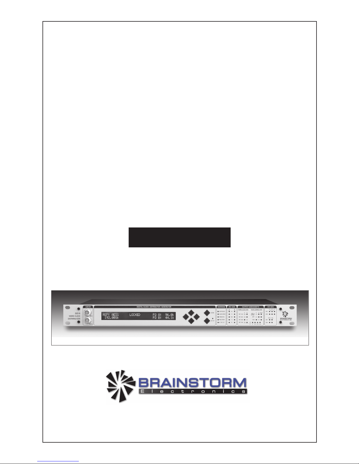
5.4. WARNING LED’S
REF ERROR: a failure of the selected reference occurred
ALT REF: the DCD-8 had to switch to the alternate reference
PHASE ERROR: one of the inputs is out of phase (see menu 41)
TERMINATION: a unit connected to one of the WC outputs is improp-
erly terminated (see menu 42)
B REFERENCE: domain B is not using the same reference as domain A
(see menu 22)
5.5. VIDEO SYNC LED’S
These LED’s are only active if the optional VSG-4 Video Sync
Generator card has been installed in your DCD-8.
For information on these LED’s and the operations of the optional
Video Sync Generator card, please refer to the VSG-4 manual.
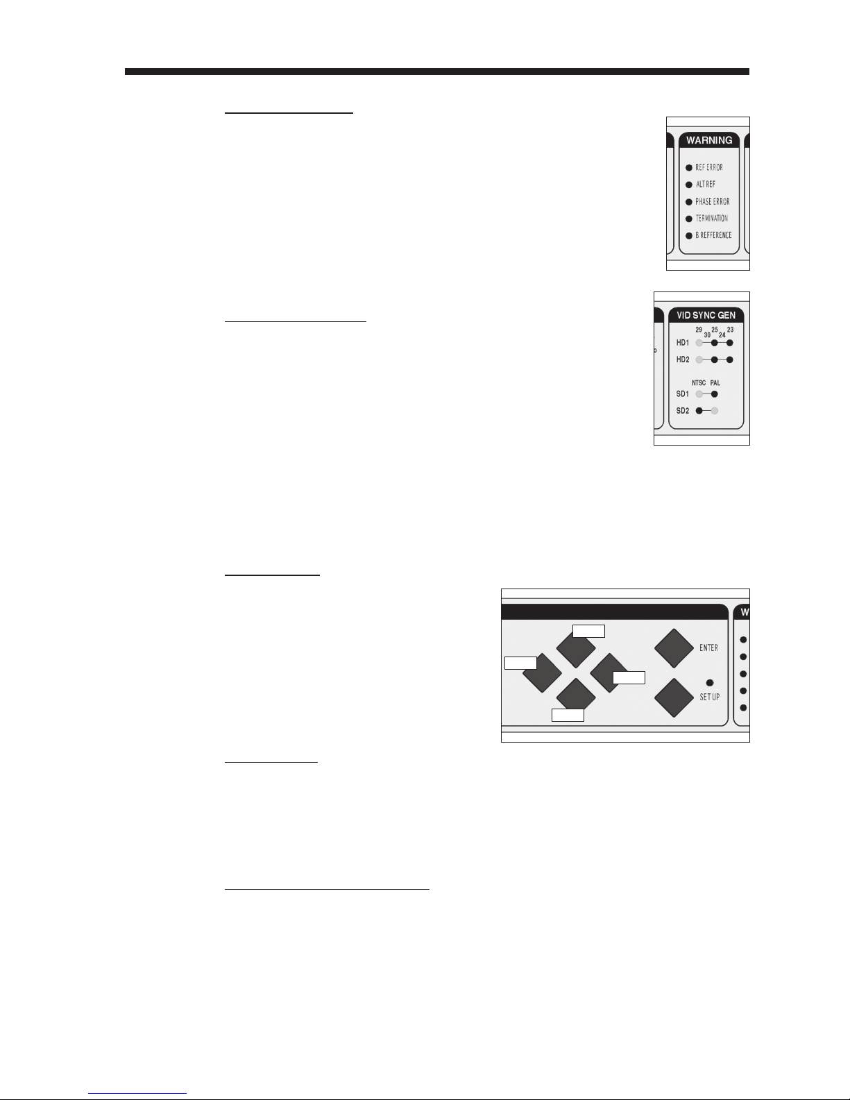
6. Navigation Keys
6.1. SET UP KEY
To access the different menus, press the
QSET UP]key.
While in Set Up mode, the SET UP LED
is on.
To exit the Set Up mode, simply press
ÌiÊQSET UP]key again.
6.2. ENTER KEY
-VÀ}ÊÌÀÕ}ÊÌiÊ`vviÀiÌÊÛ>ÕiÃÊÜÊÌÊ>vviVÌÊ>ÞÌ}°Ê"ÞÊ>vÌiÀÊÌiÊQENTER] key
is pressed will a change take place.
7iÊiÝÌ}Ê>ÊiÕÊÜÌÕÌÊ«ÀiÃÃ}ÊÌiÊQENTER] key, the changes are lost.
6.3. UP, DOWN, LEFT, RIGHT KEYS
/iÃiÊiÞÃÊ>ÀiÊ`ÀiVÌÞÊivÌÊvÊÌiÊQENTER] >`ÊQSET UP]keys. They are not labeled as such
because their function is fairly obvious.
7iÊÊ-iÌÊ1«Ê`i]ÊÌiÊQUP] >`ÊQDOWN] keys are used to change the value of the
ÃiiVÌi`Êvi`]ÊÜiÊÌiÊQLEFT] >`ÊQRIGHT] keys are used to select the different fields.
[UP] >`ÊQDOWN] keys are also used to change menu pages.
Up
Down
Left
Right
Page 8 DCD-8 User Manual
7. Menu Navigation
7.1. SELECTING AMENU
When the Set Up mode is entered, the LCD display switches to the Set Up menu last
used, with the cursor on the far left position in the upper line.
/ÊÛiÊÌÊ>ÌiÀÊiÕ]ÊÜÌÊÌiÊVÕÀÃÀÊÊÌiÊÕ««iÀÊivÌÊ«ÃÌ]Ê«ÀiÃÃÊÌiÊQUP] or
QDOWN] key.
7.2. CHANGING VALUES
/Êi`ÌÊiÊvÊÌiÊvi`ÃÊÊÌiÊ VÕÀÀiÌÊiÕ]Ê«ÀiÃÃÊÌiÊQRIGHT] ÀÊQLEFT] key to move the
VÕÀÃÀÊÌÊÌiÊ`iÃÀi`Êvi`°Ê/i]Ê«ÀiÃÃÊÌiÊQUP] ÀÊQDOWN] key to change the value.
ÌiÊÌ>ÌÊÊV>}iÊÜÊÌ>iÊivviVÌÊÕÌÊÌiÊQENTER] key is pressed. When exiting a
iÕÊÜÌÕÌÊ«ÀiÃÃ}ÊÌiÊQENTER] key, the changes are lost.
7.3. THE CURSOR
/iÊVÕÀÃÀÊ«ÃÌÊÃÊ`V>Ìi`ÊÜÌÊ>ʼ½ÊV>À>VÌiÀ]Ê«iiÌi`Ê>ÃÊÛiÀÃiÊÛ`i]Êv>Ã-
ing on and off. For alpha-numeric entry such as the User Preset NAMES, an additional
underline cursor appears beneath the digit column being adjusted.
vÌiÀÊ>ÊÛ>ÕiÊÃÊi`Ìi`]ÊÌiÊVÕÀÃÀÊV>}iÃÊÌÊ>ÊÃ`ÊÌÀ>}i]ÊÕÌÊÌiÊQENTER] key is
pressed.
vÊÌiÊVÕÀÃÀÊÃÊÛi`ÊÌÊ>ÌiÀÊvi`ÊÜÌÕÌÊ«ÀiÃÃ}ÊÌiÊQENTER] key first, the solid
triangle stays in front of the edited field to indicate a change was made but not
entered yet.
7.4. STATUSVALUES
Throughout the different menus, values appear in the display enclosed in square
brackets. These are status values.
Status values are the values actually obtained, based on a menu selection. In some
cases, this might be a rate in Hz. In others it might be a different value if the one
>Ãi`ÊvÀÊÃÊÕ>Û>>Li°ÊÀÊiÝ>«i]ÊÊiÕÊx]ÊvÊÕ`ÊÃÊÕ>Û>>LiÊQÕÌiRÊÜÊ
be displayed.
7.5. SET VS. AUTO VS. LEARN
The words “Set”, “Auto” and “Learn” are used to distinguish whether the user is establish-
ing the value (Set) or if the system is deducing the value automatically (Auto & Learn).
See chapter 11 for more information on these functions.
DCD-8 User Manual Page 9
8. Menus Description
Please note that some of the menu options will change based on your selections. As an
example, if S/PDIF has been selected in menu 31 as the optical connector format, ADAT
no longer appears as a reference option in menu 02, and vice-versa.
8.1. MENU 01: RATE A
The DCD-8 has 2 domains, A & B. Each domain can have it’s own rate. Menu 01
lets you change the A rate.
- In SET mode, a specific frequency can be selected;
- in AUTO mode, the reference’s rate is mirrored and automatically selected.
LmZmnlblma^Z\mnZekZm^bgAs'
NOTE: AUTO is not available if the reference is Internal, VSO or Video.
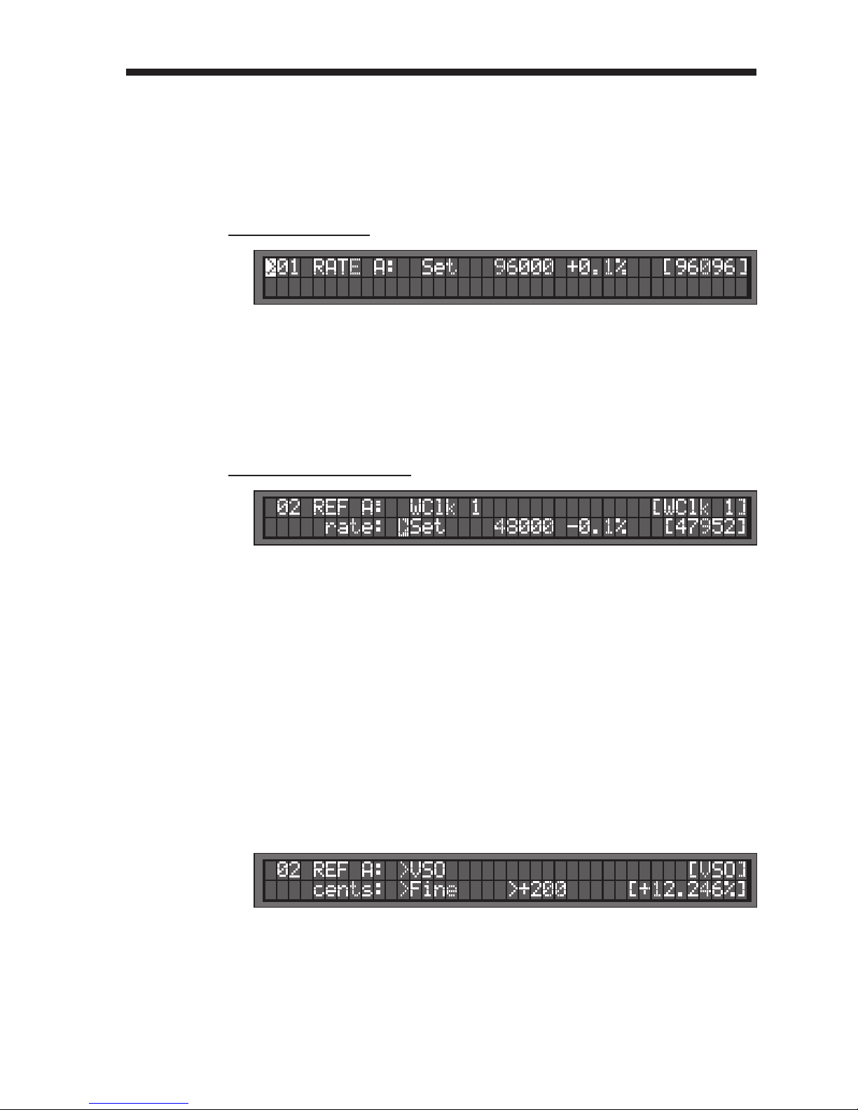
8.2. MENU 02: REFERENCE A
Menu 02 lets you select a reference for the A domain from the following choices:
Internal WClk 2 AES 2 ADAT
VSO WClk 3 AES 3 Optical
WClk 1 AES 1 S/PDIF Video
GPS: WC inputs can also accept and detect a 10MHz 5volt TTL signal, such as those
«ÀÛ`i`ÊLÞÊ>Ê*-°Ê, ÊÜÊ`ë>Þʼ£äâ½°
NOTE: Some of the choices listed above may not always be available.
Ê6-"ÊÃÊÌÊ>Û>>LiÊvÊiÕÊx£ÊÃÊÃiÌÊÌʼ>LiÊ-ÊÞ½ÊÃiiÊV>«ÌiÀÊ£Ó°Ó]Ê«°£Ç®
Ê-ÊÎÊEÊ/Ê>ÀiÊÌÊ>Û>>LiÊvÊiÕÊΣÊÃÊÃiÌÊÌʼ-É*Ê"«ÌV>½
Ê"«ÌV>ÊÃÊÌÊ>Û>>LiÊvÊiÕÊΣÊÃÊÃiÌÊÌʼ/½
When selecting an external source, a RATE menu appears on the bottom line. RATE has
2 modes: - LEARN, the DCD-8 determines the incoming rate,
- SET, the user determines the incoming rate.
For more information on Set vs. Learn, go to chapter 11.
VSO: When VSO is selected, the bottom line shows the speed adjustment, measured
in cents (semitone/100), with a parallel readout of the corresponding percentage
speed change. The VSO range is +/- 200 cents4+pahe^mhg^l!$*+'+./+mh
&*)'2*)*". Adjustments are Fine (1 cent steps) or Coarse (10 cents steps). See chapter
12 for more on VSO.
NOTE: When adjusting the VSO cents value in the menu, the changes take effect immedi-
>ÌiÞ°Ê/iÀiÊÃÊÊii`ÊÌÊ«ÀiÃÃÊQENTERRÊvÀÊiÛiÀÞÊëii`ÊV>}i°
Page 10 DCD-8 User Manual
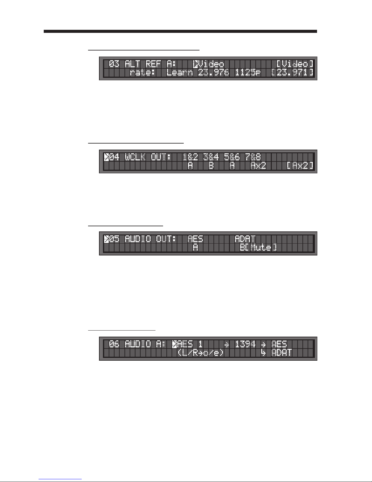
8.3. MENU 03: ALTERNATE REFERENCE A
The alternate reference is used as a backup or fallback reference in case the main
reference fails. If it happens, the DCD-8 smoothly switches to the alternate reference.
For more on Alternate Reference, see chapter 13.
Similar to menu 02, when selecting any of the external sources, a RATE menu
appears on the bottom line. The RATE can be on LEARN or SET.
8.4. MENU 04: WORD CLOCK OUT
Word Clock outputs are selected in pairs. For each pair, the choice is A or B, referring
to the rates set in menus 01 and 21 for domains A and B. Outputs 7 & 8 can also add
a multiplier to the Aor B rates (see Appendix 2 on page 23). Note that only the avail-
able choices will be displayed.
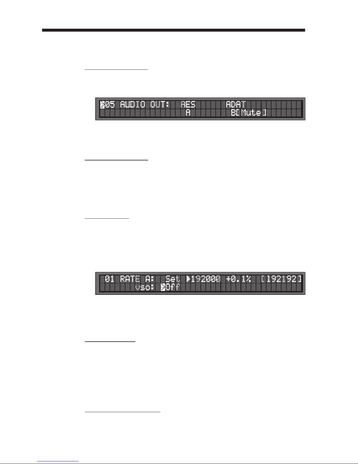
8.5. MENU 05: AUDIO OUT
One of the features of the DCD-8 is to route digital audio. Menu 05 lets you assign
Audio Aor Audio B to the AES and ADAT outputs.
NOTE: The AES field in menu 05 includes ALL AES and S/PDIF outputs.
When Ais selected, the audio source in menu 06 (Audio A) is sent to the output. If
no source is selected in menu 06 (In = Off), silent audio at the A rate is sent to the
ÕÌ«ÕÌÊ>`ÊiÕÊäxÊ`V>ÌiÃʺQÕÌiR»°Ê/iÊÃ>iÊ>««iÃÊvÀÊÊ>`ÊiÕÊäÇ°Ê
8.6. MENU 06: AUDIO A
Menus 06 selects the A audio input and the 1394 insert. It also indicates the audio
path for the Adomain, including the output(s) as set in Menu 05.
Input choices are: In=Off, AES1, AES2, AES3, S/PDIF, Optical, AES, ADAT.
Ê-ÌiÀiÊ«ÕÌÃÊ`V>ÌiʺÉ,Éi»ÊÊÌiÊÜiÀÊi]ÊÜiÀiʺÉi»ÊÀi«ÀiÃiÌÃʺ``ÉiÛi»
- The full AES input indicates “(8 chan)” in the lower line.
If the input selected is unavailable, an error message appears (see appendix 3) and
ÌiÊÃÌ>ÌÕÃÊÃÊQr"vvR°
Since 1394 is both an input and an output, it is set as an insert. In insert mode, the select-
ed audio source is sent to the FireWire device and the FW audio is sent to the selected
output(s). Note that it is not always necessary to select an input and an output. When only
sending FW to an output, an input is not required; input could be off. And when sending
DCD-8 User Manual Page 11
a source to FW only, an output is not required; output could be off.
Outputs are established by menu 5 “AUDIO OUT”, but the status of each connection
is shown also in menus 06 and 07. Output indications are:
AES
ÊÊÊÊÊÊÊÊÊÊÊÊQ-RÊ -ÊÕÌi`®
ADAT
ÊÊÊÊÊÊÊÊÊÊÊÊQ/RÊ /ÊÕÌi`®
Out=Off (no output assigned in menu 5)
WARNING: Audio routed through the DCD-8 is re clocked. If the audio source is not
synchronous with the rate of the selected domain, sound degradation will occur.
For more on Audio Routing, see chapter 14.
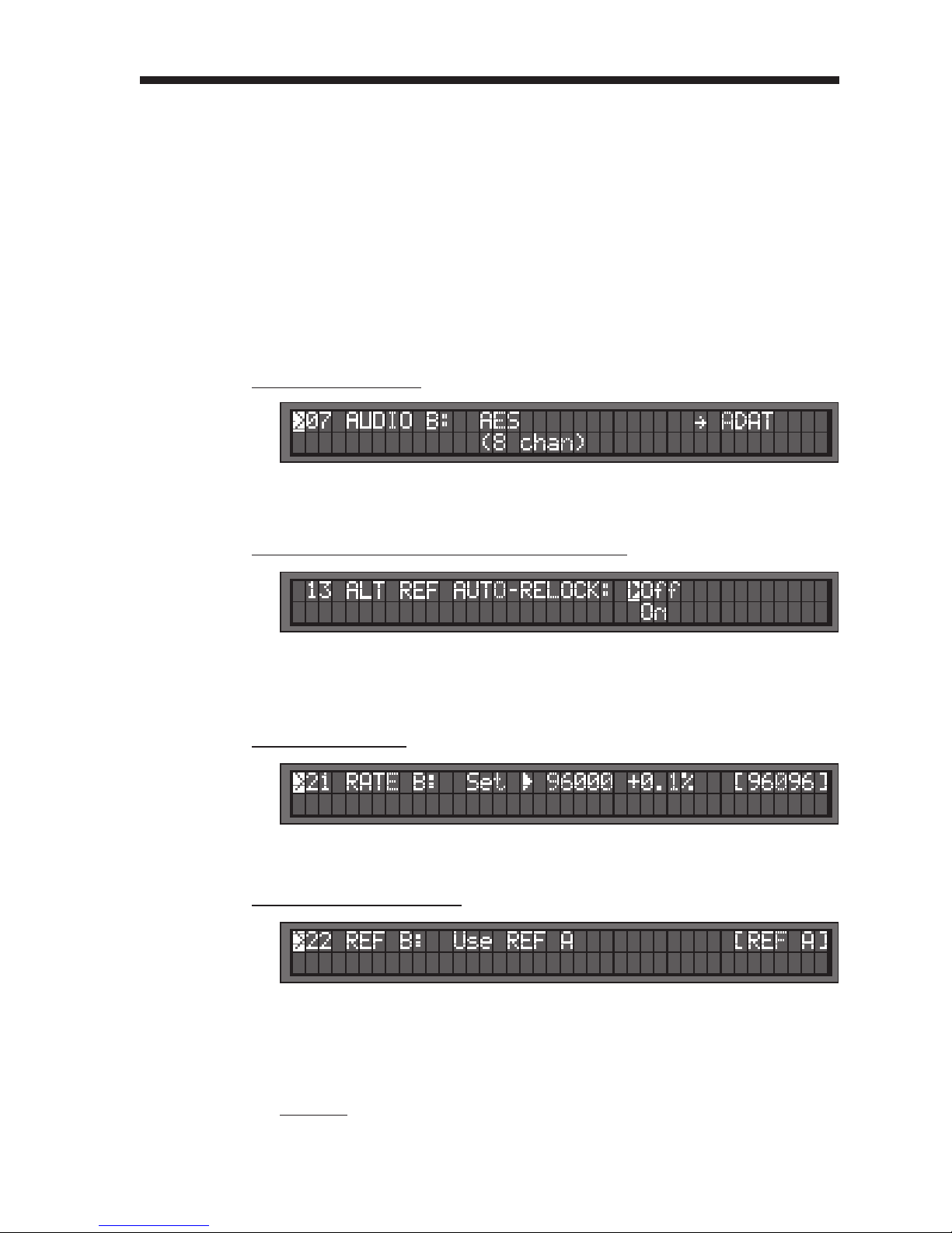
8.7. MENU 07: AUDIO B
Menus 07 selects the audio input and indicates audio path for the B domain. It is
similar to menu 06 but does not include the 1394 insert mode.
8.8. MENU 13: ALTERNATE REFERENCE AUTO-RELOCK
With this option enabled, if the PLL is locked to one of the ALT sources, then the PLL
will automatically relock to the original reference should it re-appear. For more on
Alternate Reference, see chapter 13.
8.9. MENU 21: RATE B
Menu 21 is identical to Menu 01, for domain B
8.10. MENU 22: REFERENCE B
Under most circumstances, the B domain will use the same reference as A. However,
if necessary, a separate reference can be selected for B.
/ÃÊiÕÊÃÊ`iÌV>ÊÌÊiÕÊäÓ]ÊvÀÊ`>Ê]ÊÜÌÊiÊ>``Ì>ÊVVi\ʼ1ÃiÊ
REF A’ (default setting). For more on Ref B, go to Chapter 17.
CAUTION: When selecting a reference in menu 22, domains A and B no longer
share the same reference. To alert the user of this condition, a front panel warning
LED turns on, labeled “B Reference”.
Page 12 DCD-8 User Manual
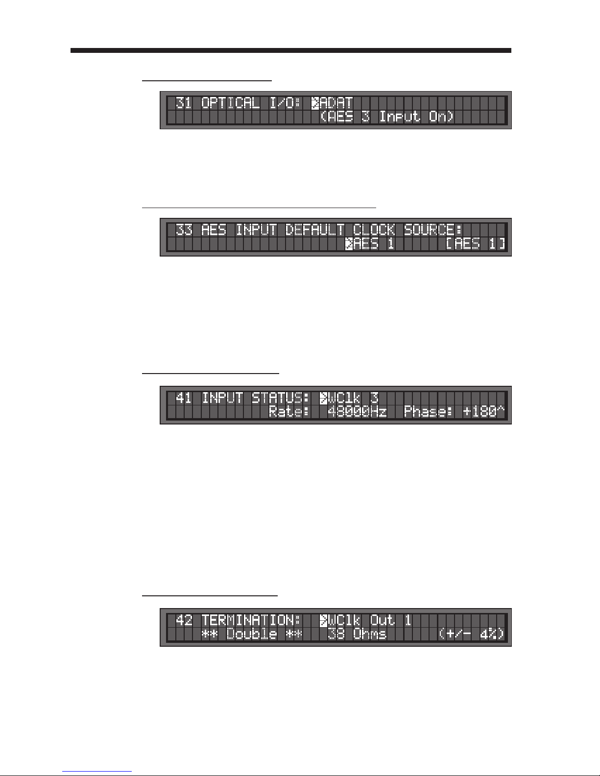
8.11. MENU 31: OPTICAL I/O
Optical I/O can be set to ADAT or S/PDIF Optical.
Note: When Optical I/O is set to S/PDIF Optical instead of ADAT, AES 3 input is
replaced by “Optical” and its front panel BNC input is disconnected.
8.12. MENU 33: AES INPUT DEFAULT CLOCK SOURCE
When any AES or S/PDIF source is used as a reference or as an audio source, it is
automatically used as the default clock source, in that order of priority. If not, the user
can determine in this menu which AES or S/PDIF source to use as the clock source.
This will be used by the DCD-8 primarily for measurements (frequency & phase).
In AUTO mode, the DCD-8 scans through each input and selects the first valid signal it
v`ðÊ7iÊÊ-Ê«ÕÌÃÊ>ÀiÊViVÌi`]ÊÃÌ>ÌÕÃÊ`V>ÌiÃÊQ-V>}R°
8.13. MENU 41: INPUT STATUS
Menu 41 displays the rate and phase of a selected input. The rate of is shown in Hz.
The phase, relative to domain A, is shown in degrees (-180º thru 180º). A positive
value indicates that the source is lagging behind domain A, while a negative value
indicates that it is leading ahead of it.
/ÊÛiÜÊ>Ê`vviÀiÌÊ«ÕÌ]Ê}Ê ÌÊÌiÊ«ÕÌÊvi`Ê>`ÊÕÃiÊ ÌiÊ QUPRÊ>`ÊQDOWNRÊiÞðÊ7iÀiÊ
there is no information (e.g. nothing plugged in) then both rate and phase fields will
show “n/a”. There is no phase field at all for Video.
The PHASE ERROR LED lights up when the source being observed in menu 41 is out
of phase, which is defined as an error greater than 36º (10%). If the source is drifting,
then the LED will go on and off as the signal goes in and out of phase.
8.14. MENU 42: TERMINATION
This page shows a termination measurement for each of the 8 word clock outputs.
These measurements are not meant to be accurate, but to give an indication.
Ideally, the value displayed should be 751. If < 481]ÊÌiÊÜÀ`ʼÕLi½ÊÃÊ`ë>Þi`ÆÊ
if < 301]ʼ/À«i½ÆÊvÊxää1]ʼ"«i½°
If any output is double or triple-terminated, the TERMINATION warning LED lights up.
DCD-8 User Manual Page 13
/ÊÛiÜÊ>Ê`vviÀiÌÊÕÌ«ÕÌ]Ê}ÊÌÊÌiÊÕÌ«ÕÌÊvi`Ê >`ÊÕÃiÊÌiÊ QUPRÊ>`ÊQDOWNRÊiÞð
NOTE: These are DC measurements. It may not measure AC coupled inputs correctly.
8.15. MENUS 51-59: VIDEO OPTION
Menus 51 to 59 are assigned to the optional Video Sync Generator (VSG-4) and
only appear if this card has been installed. For more info on these menus, see the
VSG-4 manual.
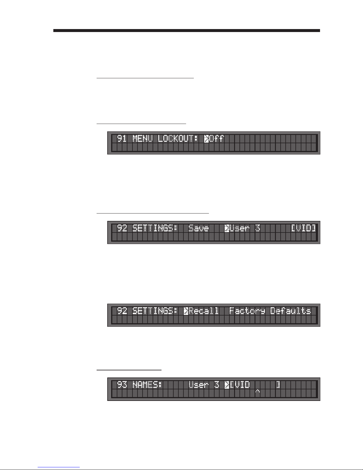
8.16. MENU 91: MENU LOCKOUT
To prevent accidental changes, the DCD-8 menus can be locked out. In this mode,
no changes are permitted.
If a change is attempted while the menus are locked out, an error message appears
on the LCD display: “ERROR - Menus Locked Out.”
8.17. MENU 92: SETTINGS (USER PRESETS)
Menu 92 is used to store and recall user presets. The DCD-8 has provisions to store up
to 4 different presets, labeled USER 0 through USER 3. A name can be associated with
each preset which appears to the right of the display (see Menu 93).
To store a preset, select SAVE. Then select the user preset number you would like to
Ã>ÛiÊÌÊ>`Ê«ÀiÃÃÊQENTERR°Ê/ÊÀiV>Ê>Ê«ÀiÃiÌ]ÊÃiiVÌÊ,°Ê/iÊÃiiVÌÊÌiÊÕÃiÀÊ«Ài-
ÃiÌÊÕLiÀÊÞÕÊÜÕ`ÊiÊÌÊÀiV>Ê>`Ê«ÀiÃÃÊQENTERR°
FACTORY DEFAULTS: There is an additional preset holding the Factory Defaults.
This preset can only be recalled and cannot be modified. For details on the Factory
Defaults, see Appendix 6.
8.18. MENU 93: NAMES
iÕÊÎÊiÌÃÊÞÕÊ`iviÊ>ʼ>i½ÊvÀÊi>VÊvÊÌiÊ{ÊÕÃiÀÊ«ÀiÃiÌðÊThey can be up to 8
characters long. Use the left/right keys to select a character, then use the up/down
keys to edit it. When a text character is being adjusted, there will be a single caret
symbol (^) in the line immediately below it which serves as a cursor. The range of
possible characters in each position is A thru Z, 0 thru 9, dash, period and space.
Page 14 DCD-8 User Manual
NOTE: You can make a change to User X, go have a look at User Y, then come back
to User X and your change will still be there, whether saved or not. Of course, if you
leave the menu, you will lose any unsaved data, as usual.
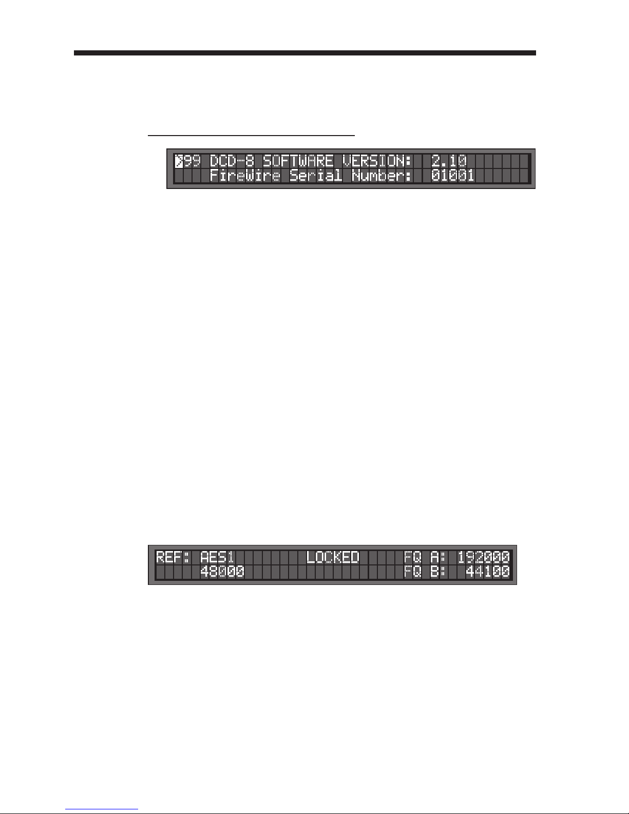
8.19. MENU 99: DCD-8 SOFTWARE VERSION
Menu 99 displays the unit’s software version number and its FireWire serial num-
ber. The FireWire serial number is pre-programmed at the factory and cannot be
changed. Identification over FireWire has to be different for each DCD-8 so that
more than one of them can co-exist on the same bus.
*",/ /Ê "/\Ê,iiLiÀÊÌÊ>Ü>ÞÃÊ«ÀiÃÃÊÌiÊQENTERRÊiÞÊÌÊÃ>ÛiÊÞÕÀÊÃiÌÌ}ÃÊ«ÀÀÊ
ÌÊiÝÌ}Ê>ÊiÕÊÀÊÌÊiÝÌ}ÊÌiÊ-/Ê1*Ê`i°Ê ÊV>}iÊÜÊÌ>iÊ«>ViÊÕÌÊÌiÊQENTERRÊ
key is pressed.
9. Non-Volatile Storage
The DCD-8 has 4 user presets and a factory default preset (see menu 92).
In addition, it has non-volatile memory holding the current settings. This includes all DCD-8
settings such as rate and reference selections as well as output assignments. This memory
is continuously updated so that, when the unit is turned on, it is in the same condition as it
was when powered down.
NOTE: You should wait approximately 10 seconds after a change was entered before pow-
ering down, to allow for the flash memory to be updated.
10. Lock Status
The lock status of the DCD-8 is displayed in the center of the LCD display. Below are
ma^0]b__^k^gmihllb[bebmb^lZg]paZmma^rbg]b\Zm^3
GHK>? K^_^k^g\^fbllbg`
UNLOCKED Unable to lock
LE>PIEEblmkrbg`mheh\d
LOCKED -- Loose Lock
LOCKED - Lock confirmation phase
EH<D>=@hh]Zg]eh\d^]
AHE=BG@ Ahe]bg`eZlmdghpg_k^jn^g\rZ_m^keh\d_Zbenk^
Ma^=<=&1ZepZrlmkb^lmheh\dmhbmlbginm'Hg\^ma^kZm^aZl[^^g^lmZ[ebla^]!L>M
hkE>:KG"%b_ma^k^_^k^g\^blh__li^^][rfhk^maZg*)%bmlpbm\a^lmhLE>P'
Ghm^maZmpbmaob]^h%ma^*)kne^Ziieb^lmhma^ahkbshgmZe_k^jn^g\rZg]ghmma^
frame rate.

DCD-8 User Manual Page 15
11. Defining the rate: Set, Auto & Learn
Part of the DCD-8’s great flexibility comes from the fact that the rate generated does not have
to match the rate of the reference. Different frequencies can be cross-locked if necessary.
This is done through the use of the SET, AUTO and LEARN functions.
11.1. RATE MENU
In the Rate menu, the DCD-8 offers a choice between SET and AUTO:
- SET lets the user select a specific rate;
- AUTO mirrors the Reference menu (i.e. with a 48k reference, the output is 48K).
Keep in mind that, when locked to an external reference, the DCD-8 always tracks small
variations (see examples in 11.5 below).
NOTE: Auto is not available if the reference selected is Internal or Video.
11.2. REFERENCE MENU
In the Reference menu, the DCD-8 offers a choice between LEARN and SET:
- with LEARN, the DCD-8 measures the input reference and determines it’s rate;
- with SET, the user defines the expected rate.
Most of the time LEARN will work fine. However, at times, the user may choose SET to be
sure the DCD-8 does not misinterpret an input frequency which is slightly incorrect. The
SET mode may also be chosen for more fail-safe operation, in that there is no chance that
the DCD-8 will re-define a frequency which drifts over time.
To illustrate this, let’s look at a reference frequency of 95,950Hz. This frequency is slightly
below the standard 96k rate but slightly above the pulled down 96k (95,904Hz).
- If the DCD-8 interprets this as 96k, it will run slow by 0.052%;
- if it interprets it as a pulled down 96k, it will run fast by 0.047%
In SET mode, the user can make that choice; in LEARN mode, the DCD-8 automatically
selectes the closest frequency, i.e. the pulled down 96Kin this case.
11.3 ABOUT USING THE SET MODE FOR THE REFERENCE
When SETTING the rate of the reference, there is the possibility that the selected rate will
not match the measured rate (actual rate). If that is the case, the DCD-8 will still lock to the
reference but the output frequency will be adjusted proportionately.
WARNING: When using this function, the user can potentially mislead the DCD-8 and
affect the output frequency, even if that is also SET. This could be done intentionally, but
caution should be used here.
For example, if the input reference is SET for PAL, and NTSC video reference is connected,
the output frequency SET at 44100Hz will actually be 52867Hz (44100 x 29.97/25).

Page 16 DCD-8 User Manual
11.4 OFF SPEED INDICATION WITH A SET REFERENCE
When the reference is detected to be off speed by more than 1.5%, the DCD-8 alerts the
user as follows. The main display alternates between the normal LOCKED status and the
OFF SPEED indication, staying about 2 seconds on each one. The measured reference
vÀiµÕiVÞÊÃÊÃÜÊÕ`iÀÊÌiÊÜÀ`Ãʼ"vvÊ-«ii`½ÊvÀÊV«>ÀÃÊÜÌÊÌiÊiÝ«iVÌi`ÊÀ>Ìi]Ê
shown under the reference.
Here is an example of the Off Speed indication for Ref AWC1.
For comparison, here is another example for Ref AVideo, off speed:
11.5 HOW DOESIT ALL WORK?
To help To help understand how these different modes interact, let’s take a look at a few examples.
Note: 48.003 is only used in these examples to illustrate that the DCD-8, when locked to
the reference, will track small variations. 44.100 is used to illustrate when a completely dif-
ferent rate is supplied or intended.s.
UÊ ,iv\Ê, ÊÊEÊ,>Ìi\Ê1/"ÊÊThe DCD-8 LEARNSthe incoming rate and the
48.003k in = 48.003k out ➢output rate matches the input. In this case, no rate
44.1k in = 44.1k out needs to be programmed.
UÊ ,iv\Ê, ÊÊEÊ,>Ìi\Ê-/Ê{n®ÊÊ/iÊnÊ, -ÊÌiÊV}ÊÀ>Ìi°Ê``}Ê
48.003k in = 48.003k out ➢SET assigns the nominal output rate.
44.1k in = 48k out
UÊ ,iv\Ê-/Ê{n®ÊÊEÊ,>Ìi\Ê1/"ÊÊ/iÊnÊ-/-ÊÌiÊiÝ«iVÌi`Ê«ÕÌÊÀ>Ìi°
48.003k in = 48.003Kout ➢With AUTO, the output rate mirrors the reference.
{{°£ÊÊrÊ{{°£ÊÕÌʼ"vvÊ-«ii`½®ÊÊ"Ê-*Ê`V>ÌiÃÊÌiÊÀiviÀiViÊÃÊÌÊ{n°
UÊ ,iv\Ê-/Ê{n®ÊEÊ,>Ìi\Ê-/Ê{{°£®ÊÊ
The DCD-8 SETSthe expected input rate and the
48.003k in = 44.103k out ➢
expected output rate. An inputt rate different than
{{°£ÊÊrÊ{ä°x£ÇÊÕÌʼ"vvÊ-«ii`½®ÊÊ
what was SET provides a proportionate speed change
12. VSO
VSO is selected in the Reference menus (02 for domain A and 22 for domain B). In the main
display, when domain Ais in VSO mode and domain B is following A:
NOTE: With VSO activated, the displayed frequencies on the right side of the LCD are not
the resultant frequencies but rather the base frequency, prior to VSO being applied.

DCD-8 User Manual Page 17
12.1. DOMAIN B VSO
Domain B can be independently in VSO mode.
However, if set to “Use REF A” and if domain A is in VSO mode, then domain B will track
the VSO speed setting of domain A. So A could be 48000, and B 44100, and both
VSO’d up 100 cents by adjusting the REF A VSO setting. (NOTE: the long term relative
accuracy of the two rates is considerably reduced in this mode.)
12.2. VSO & THE VSG-4 OPTION CARD
UÊ6"Ê"1/\Ê Ê-Ê" 9\
With the VSG-4 option card installed, when SD only is enabled (menu 52), VSO opera-
tion in domain A is prohibited as the SD video cannot track the varying wordclock rate.
The VSO option will not appear in menu 02.
To eliminate this conflict, if the video outputs are not being used, switch off the video op-
tion. For more on this, please refer to the VSG-4 User’s Manual.
UÊ6"Ê"1/\Ê ÊÊEÊ-\
When the HD and SD outputs are enabled and the VSG-4 has taken over REF B, domain
A VSO is allowed.
"/\ÊvÊÌiÊÊ,ivÊ>ÃÊLiiÊÃiÌÊÌʼ1ÃiÊ,ʽÊÊiÕÊxÓ]ÊÌiÊÛ`iÊÕÌ«ÕÌÊÜÊÌÀ>VÊ
the Ref A rate prior to VSO. As a result, the video sync “edge” alignment to the word
clock will be turned off (see VSG-4 User Manual).
13. Source Reference Failure Options
In the event of failure of the external reference, the DCD-8 has 2 different ways of insuring
that the WC output remains safely uninterrupted.
13.1. MAIN REFERENCE FAILURE WITH NO ALTERNATE REFERENCE SET
If no alternate reference was set in menu 03, the DCD-8 holds the last known frequency
and displays “HOLDING” as a lock status.
If a signal is still present at the main reference input, the DCD-8 automatically attempts to
VÊÌÊÌÊ>}>°ÊvÊÌÊÃÕVVii`Ã]ÊÌÊ}iÃÊÌÀÕ}ÊÌiÊÀ>ʼVi`½ÊÃiµÕiViÆÊvÊÌ]ÊÌÊVÌ-
ues holding and attempts to Lock to the main reference again.
vÊÊÃ}>ÊÃÊ«ÀiÃiÌÊ>ÌÊÌiÊ>ÊÀiviÀiViÊ«ÕÌ]ÊÌiÊnÊÜÊÀi>Êʼ" ½Ê
mode indefinitely.
13.2. MAIN REFERENCE FAILURE WITH AN ALTERNATE REFERENCE SET
If an alternate reference was set in menu 03, the DCD-8 goes into the following cycle:
UÊ-Ìi«Ê£\ÊÊÌiÊ*ÊÃÜÌViÃÊÌÊÌiÊÌiÀ>ÌiÊ,iviÀiVi
- the generator goes in HOLDING mode, holding the last known frequency.
UÊ-Ìi«ÊÓ\ÊvÌiÀÊ>LÕÌÊÓÊÃiV`Ã]ÊÌiÊ}iiÀ>ÌÀÊÃÜÌViÃÊÃÌÞÊÌÊÌiÊ>ÌiÀ>ÌiÊÀiviÀiVi°
During Step 1, the Lock status on the LCD display indicates “HOLDING”.
ÕÀ}Ê-Ìi«ÊÓ]ÊÌiÊVÊÃÌ>ÌÕÃÊ}iÃÊvÀʼLOCKED --” to “LOCKED” as it reaches full lock.
In the event of failure of the Alternate Reference, the DCD-8 goes back through steps 1 and
2, but this time, Internal Crystal is used as the new reference.
Page 18 DCD-8 User Manual
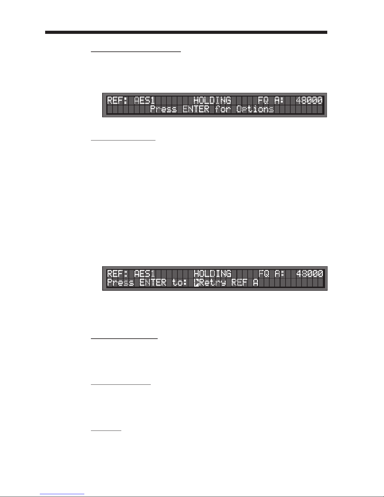
13.3. FRONT PANEL WARNINGS
After a failure of the reference, the red REF ERROR warning LED starts flasing and the
bottom line of the LCD display flashes the message “PRESS ENTER FOR OPTIONS”. The
options available varry according to the circumstances.
13.4. REVERT TO REF A
If an Alternate Reference was set in Menu 3, when the original reference re-apears, the
DCD-8 can revert to it automatically or manually. This is set in menu 13.
UÊ1/","Ê \
With Auto-Reclock enabled, the DCD-8 smoothly relocks to the original reference when
it re-appears. This is similar to the Auto relock described in 13.1 above.
The options available are: - Clear REF ERROR
- Exit with no change
UÊ1/","Ê-\
With Auto-Reclock disabled, reverting to the original reference is done manually.
The options available are: - Retry REF A
- Exit with no change
- Clear REF ERROR
*ÀiÃÃ}ʼ,iÌÀÞÊ,ʽÊÜÊ>iÊÌiÊnÊÀiÛiÀÌÊÃÌÞÊÌÊ,Ê°
NOTE: This transition will be smooth only if the DCD-8 was locked to either the alter-
nate reference or the internal crystal before selecting RETRY REF A.
13.5. ERROR MESSAGES
The following messages appear in the LCD display when appropriate:
REF RETRY FAILED (no valid reference was available for retry)
REF RETRY REQUIRED PLL RESET (DCD-8 was not locked - see NOTE above)
13.6. WARNING LEDS
REF ERROR: This red LED flashes as soon as the main reference fails.
ALT REF: This green LED lights up as soon as the DCD-8 switches to the alternate refer-
ence. It flashes if the Alternate Reference fails.
13.7. REF B
Under most circumstances, REF Awill be used by domains A & B. However, in menu 07,
a separate reference can be set for domain B. But, the Alternate Reference option is only
available for the main reference (REF A) and not REF B. If REF B fails, it will go through the
procedure described in 13.1 above.
DCD-8 User Manual Page 19
14. Audio Routing
The DCD-8 is able to re-clock an audio input and route it to an audio output. Audio routing is
done through either of the 2 domains. The audio path for Domain A is indicated in Menu 06
and for Domain B in Menu 07.
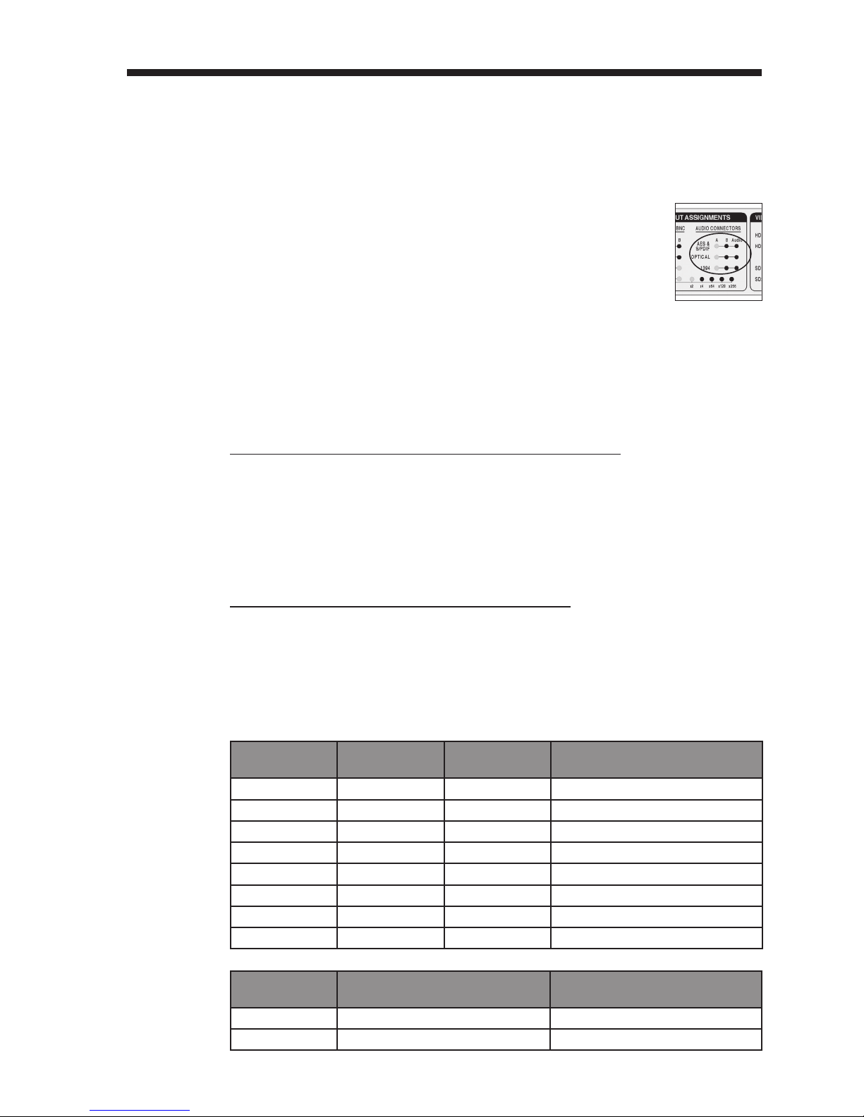
"ÊÌiÊvÀÌÊ«>i]ÊÕ`iÀʼ"1/*1/Ê-- /-ÊÉÊ1"Ê
" /",-½]Ê>ÀiÊÎʼÕ`½Ê½Ã°Ê/iÃiÊ`V>ÌiÊÌ>ÌÊ>Õ`ÊÃÊLi}Ê
routed to the corresponding audio connector (AES & S/PDIF, Optical and
Ài7Ài®°Ê/iÀiÊ>ÀiÊ>ÃÊÎʼ½Ê>`ÊÎʼ½Ê½Ã°Ê/iÃiÊ`V>ÌiÊÜVÊ«ÕÌÊ
is being routed.
Outputs for both domains are set in Menu 05. Domain A input is set in Menu 06 and domain
B in Menu 07. FireWire is set as an insert and is only available in Domain A (menu 06).
WARNING: When routing audio through the DCD-8, the audio is re-clocked. It is impera-
tive that the audio source be synchronous with the domain selected. Otherwise, signal
degradation will occur.
14.1. MAPPING OPTION 1: LEFT TO ODD AND RIGHT TO EVEN
In menu 06 & 07, when selecting a stereo source as the input (AES or S/PDIF), the DCD-8
}ÛiÃÊÞÕÊÌiÊ«ÌÊÉ,ÊÊÉi®ÊÜiÀiʼ½Ê>`ʼi½ÊÃÌ>`ÊvÀʼ``½Ê>`ʼiÛi½°Ê7ÌÊÌÃÊ
option, the left channel is routed to channels 1,3,5,7 and the right channel to 2,4,6,8 of
the multichannel outputs (FireWire and the ADAT). Both channels are also routed to all
the stereo outputs (AES or S/PDIF).
14.2. MAPPING OPTION 2: 8 CHANNEL ROUTING MAP
When selecting AES (8 chan) or ADAT as a source, or when inserting FireWire, the DCD-8
uses a routing map as described below. This routing map will vary, depending on the rate
at which the router is running due to the various bit-splitting formats accepted by the DCD-8
(S/MUX and AES double-wire).
For more on digital audio formats, go to Appendix 4 on page 25.
FireWire
44.1 to 96k
ADAT
44.1 to 48k
ADAT S/MUX
88.2 to 96k
AES & S/PDIF
44.1 to 96k
111&2 AES-1 L
223&4 AES-1 R
335&6 AES-2 L
447&8 AES-2 R
5 5 S/PDIF L
6 6 S/PDIF R
7 7 AES-3/ Optical L
8 8 AES-3 /Optical R
FireWire
176.4 to 192k
ADAT S/MUX IV
176.4 to 192k
AES Double Wire
176.4 to 192k
11&2&3&4 AES-1
25&6&7&8 AES-2
Table of contents
Other Brainstorm Recording Equipment manuals


