Cloud DCM-1 User manual
Clearly better sound
CLOUD DCM1 & DCM1e
DIGITALLY CONTROLLED ZONE MIXERS
General Description
The Cloud DCM1 and DCM1e are analogue multi-zone audio
mixers. A digital control system, using a front-panel LCD display
and a simple, minimal set of controls replace the relatively large
number of switch and rotary controls found on conventional units,
yet provide far greater exibility of conguration than would be
possible with such units. The mixers provide a simple, reliable and
elegant method of providing audio to multiple zones in retail outlets,
bars, hotels, schools, conference centres, ofces, factories and other
types of premises. Once congured, the mixers allow zones to be
combined or separated as space utilisation of the building demands.
The mixers allow connection of eight line level sources, and provide
eight zone outputs, two of which are stereo. Any source can be
routed to any zone, and the music level in each zone can be adjusted
independently. A wide range of conguration options is available to
the installer to optimise the system to the premises and the client’s
requirements, such as restricting source selection in some zones or
dening minimum and maximum volume levels.
A range of optional remote plates is available to permit music
control in any or all zones and external inputs from mic and line
sources. (See separate datasheets for Cloud accessories CDR-1,
LE-1, BE-1, ME-1.) While the DCM1 and DCM1e are also directly
compatible with the Cloud PM range of paging microphones, most
third-party paging systems are easily integrated. In common with all
Cloud installed audio products,a Music Mute input is provided to aid
compliance with local Fire Regulations.
The DCM1 has been designed to be completely self-contained, and
can be fully congured and controlled without a computer of any
kind. However, a software Conguration Tool is available (a free
download) to enable conguration from a computer if this method
is preferred.
The DCM1e greatly extends the DCM1’s functionality by adding an
Ethernet interface and an internal web server, allowing control from
a smartphone, laptop, tablet device or computer via a web browser.
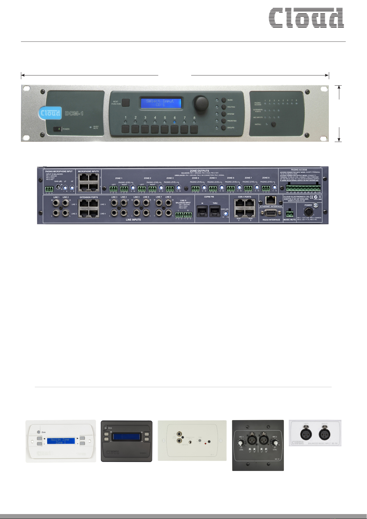
DCM1 - FrontView
DCM1e - Rear View
All Cloud products are exclusively designed in the UK.
Every Cloud product is exhaustively tested for electronic performance and sonic perfection in Shefeld, England.
482.6 mm
19”
88 mm (2U)
3½”
DCM1 & DCM1e Accessories (examples)
CDR-1F CDR-1 LE-1 (UK Version) ME-1A (US Version) BE-1M (Media Version)
Remote Control Plate Remote Control Plate Line Input Module Microphone Input
Module
Balanced Line Input
Module

Clearly better sound
DCM1e Control Using Web Browser (sample menus when used with a smartphone)
Conguration Menu Group Assignment Menu Music Controls per Zone
Input Selection Per Zone
Paging Assignment Security Settings
Network Setup Menu
Further Examples Showing Complete Menus

Clearly better sound
• 8 stereo line inputs (1 balanced), with input level trims (via menu
system)
• 8 balanced line outputs (2 stereo + 6 mono)
• Any source may be routed to any zone at any level
• 4 Extension Ports for optional remote line input modules
(balanced or unbalanced), using Cat 5 UTP cable
• 4 Mic Inputs for optional remote mic input modules, using
Cat 5 UTP cable
• External inputs (mic or line) may be routed to any zone
• RJ45 interface for Cloud PM Series digital paging microphones
• Separate analogue paging mic input with standard short-to-
ground zone selection
• Paging to all zones with fully programmable override logic
• Supports up to 100 CDR-1 Remote Controls (optional), in any
wiring configuration, using Cat 5 UTP cable
• Remote control of source, level, EQ and group enable via
CDR-1 plates
• 2 x 16 character LCD dot-matrix display (both DCM1/DCM1e
and CDR-1)
• Four definable zone groups; groups have same selection options
as zones
• Any line input may have priority in any zone; configurable per-
zone
• Configurable source selection restriction, per-zone
• Key-protected “Installer” mode (both DCM1/DCM1e and
CDR-1) prevents user access to configuration menus
• Inputs, zones and groups can be named
• RS232 interface for control by third-party control systems
• Paging access port may be reconfigured as eight GPIO ports,
under RS-232 or Ethernet (DCM1e only) control
• Front-panel LEDs confirm remote access
• Optional per-zone EQ cards to suit a range of popular installation
loudspeakers
• Software Configuration Tool available (free download) to permit
easy configuration from a computer
• Self-contained - can be fully configured and controlled without a
computer if preferred
• Multiple mixers may be cascaded to create larger systems
• External Music Mute input for interfacing with emergency
systems
• Any input (mic or line) may be assigned as Emergency Input,
overriding Music Mute
• 2U 19” rack-mounting unit
DCM1e only – Additional features
• Ethernet port with internal web server
• Control over main user functions from web-capable devices
• Extended range of password-protected functions
• Ethernet to RS232 bridge may be used to send commands to
third-party equipment
Key Features
System Example - Hotel/Large Restaurant (DCM1)
The system shown could typically be a hotel or large
restaurant, and illustrate how some of the DCM1’s
many features may be used in practice:
• The large area has two CDR-1 remote controls
in the same zone; typically, these might be adjacent to
doors at opposite ends of the room.
• Two of the areas are separated by a folding partition
which may be removed to create one large space. By
assigning these two zones to a Group within the DCM1,
the two zones can be treated as one for audio purposes
when the partition is removed and return to two
separate zones when it is reinstated.
• Each half of the partitioned area also has an ME-1
mic input plate. Because these have been wired back to
the DCM 1 independently, each can be made available
to their respective room halves as and when required.
Alternatively, it may be that they are only required
when the partition is folded back; in this case they are
activated for the Group instead.
• If the model of mixer is a DCM1e, system control is
available to the user via a web browser on an Internet-
capable device. Browser control can be congured
at installation so that only the operational features
required by the venue staff are accessible to them; all
other functions are password-protected.
AREA 3
POWER
AMPLIFIERS
OTHER
AREAS
CD
JUKEBOX
OFF-AIR
RECEIVER
MP3
PLAYER
DOCK
MUSIC
SERVER
CDR-1
CDR-1
CDR-1
DCM1 or
DCM1e
INPUT 1
INPUT 6
INPUT 4
INPUT 8
INPUT 2
INPUT 7
INPUT 3
INPUT 5
CDPM
MIC 1
MIC 4
MIC 2
MIC 3
PAGING MIC
PAGING ACCESS
CDR-1PORTS
1
2
3
4
ZONE 5
ZONE 3
ZONE 2
ZONE 6
ZONE 8
ZONE 4
ZONE 7
ZONE 1
AREAS 1 & 2
ME-1
ME-1
PARTITION
AREA 4
CDR-1
ETHERNET
COMPUTER
OR TABLET
Wireless Access Point
or Router for DCM1e
only.
Clearly better sound
Technical Specications
Line Inputs
Frequency Response 20 Hz - 20k Hz ±1 dB
Distortion <0.05 %, 20 Hz - 20k Hz
Sensitivity 195 mV (-12 dBu) to 3.1 V (+12 dBu)
Input Gain Control 24 dB range
Input Impedance 47k Ω
Headroom >+10 dB
Noise -90 dB A weighted (0 dB gain)
Equalisation HF: ±14 dB/10k Hz
MID: ±14 dB/1200 Hz
LF: ±14 dB/50 Hz
Paging Microphone Inputs
Frequency Response 100 Hz / -3 dB(lter) to 20 kHz
±0.5dB
Distortion <0.05% 20 Hz-20k Hz
Gain Range 10 dB - 50 dB
Input Impedance >2k Ω (balanced)
Phantom Power +12 V (PCB jumper for on/off)
Headroom >20 dB
Noise -120 dB EIN 22 Hz - 22k Hz (150 Ω)
Equalisation HF: ±10 dB/5k Hz
LF: ±10 dB/100 Hz
Outputs
Balanced Zone Outputs 775 mV (0 dBu)
Minimum load impedance 600 Ω
Maximum output level +10 dBu (2.6 V)
External Power Supply
External Supply Input 100 V-240V AC; 47-63 Hz; 1.35 A
Power supply +12 V, 3 A; -12 V 1 A
Physical
Dimensions (w x h x d) 482.6 mm x 88 mm (2U) x 170 mm
19” x 31/2” 63/5”
Dimensions (packed) 570 mm x 270 mm x 220 mm
22” x 11” x 9”
Weight 3.12 kg (7 lbs) net
4 kg (8.8 lbs) packed
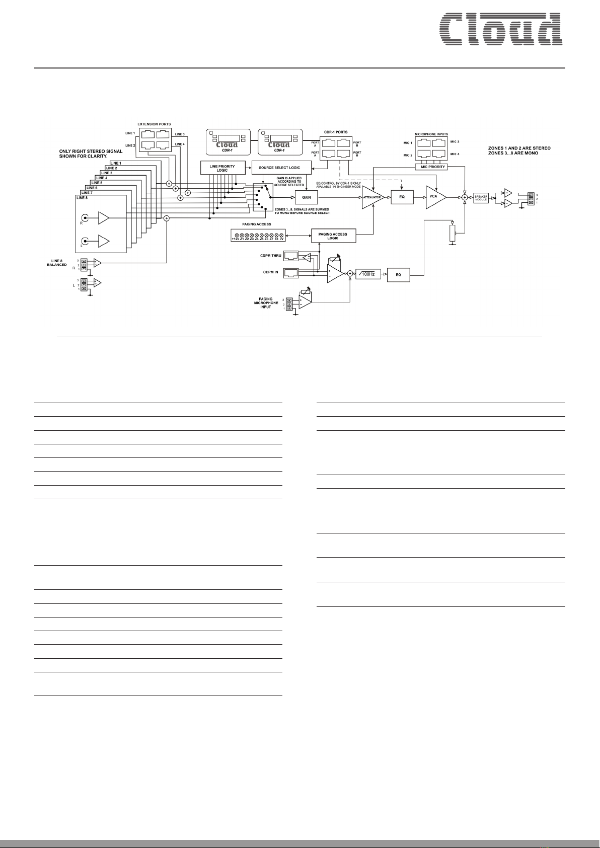
Block Diagram

Clearly better sound
Graphs
CloudElectronics Ltd DCM-1LineInput FrequencyResponse
Stereo Output
-10
+10
-9
-8
-7
-6
-5
-4
-3
-2
-1
-0
+1
+2
+3
+4
+5
+6
+7
+8
+9
d
B
u
20 20k50 100 200 500 1k 2k 5k 10k
Hz
CloudElectronics Ltd DCM-1LineInput EQ Curves
ColorSweep Trace Line StyleThick Data Axis Comm en t
1 1 Black Soli d 1 Anlr.Ampl Le ft Treble Full Boo st
2 1 Black Soli d 1 Anlr.Ampl Le ft Treble Full Cu t
3 1 Black Soli d 1 Anlr.Ampl Le ft Mid Full Cut
4 1 Black Soli d 1 Anlr.Ampl Le ft Mid Full Boost
5 1 Black Soli d 1 Anlr.Ampl Le ft Bass Full Boost
6 1 Black Soli d 1 Anlr.Ampl Le ft Bass Full Cut
-14
+14
-12
-10
-8
-6
-4
-2
+0
+2
+4
+6
+8
+10
+12
d
B
r
A
20 20k50 100 200 500 1k 2k 5k 10k
CloudElectronics Ltd DCM-1LineInput FrequencyResponse
Stereo Output
-10
+10
-9
-8
-7
-6
-5
-4
-3
-2
-1
-0
+1
+2
+3
+4
+5
+6
+7
+8
+9
d
B
u
20 20k50 100 200 500 1k 2k 5k 10k
Hz
CloudElectronics Ltd DCM-1AdjacentLineInput Crosstalk
-120
+0
-115
-110
-105
-100
-95
-90
-85
-80
-75
-70
-65
-60
-55
-50
-45
-40
-35
-30
-25
-20
-15
-10
-5
d
B
C
r
o
s
s
t
a
l
k
20 20k50 100 200 500 1k 2k 5k 10k
Hz Frequency
DCM1/DCM1e Line Input Frequency Response Stereo Output
DCM1/DCM1e Adjacent Line Input Crosstalk
DCM1/DCM1e Line Input EQ Curves
DCM1/DCM1e Line Input Frequency Response Stereo Output
CloudElectronics Ltd DCM-1AdjacentZoneOutputCrosstalk
-120
+0
-115
-110
-105
-100
-95
-90
-85
-80
-75
-70
-65
-60
-55
-50
-45
-40
-35
-30
-25
-20
-15
-10
-5
d
B
C
r
o
s
s
t
a
l
k
20 20k50 100 200 500 1k 2k 5k 10k
Hz Frequency
DCM1/DCM1e Adjacent Line Input Crosstalk

Clearly better sound
Architect’s and Engineer’s Specication
The Zone Mixer’s audio signal paths shall be fully analogue in design;
there shall be a simple menu/display system on the front panel for
accessing all system controls and conguration options. It shall be
possible to access all control functions without the use of any external
computers or software. A PC-compatible software application shall
be available; this shall interface with the Zone Mixer via an RS232
connection and shall provide an alternative method of accessing all
control and conguration options.
Two versions of the Zone Mixer shall be available;these shall be identical
in terms of their audio functions. One shall include an standard RJ45
Ethernet interface and internal web server; on this version it shall be
possible to access main control functions from a standard web browser
on devices connected to the same network as the Zone Mixer.
The Zone Mixer shall have 8 stereo line channels, 4 microphone inputs
and a paging mic input. Line inputs shall be on RCA jacks; one shall also
be available as a balanced input on Euroblock connectors; four shall
also have RJ45 sockets providing balanced inputs for the connection
of optional balanced or unbalanced stereo external connection
modules.The microphone inputs shall be balanced on RJ45 sockets for
connection of optional external modules. The Line Inputs shall each
have level trim adjustment available via the menu system.The remote
modules shall be available in a range of sizes and nishes.
The Zone outputs shall be balanced on Euroblock connectors. At
least two shall be stereo, the remainder mono. It shall be possible to
adjust the following parameters for each Zone output: Level, Maximum
and Minimum Levels; EQ (3-bands). It shall be possible to route any
microphone or line input to any Zone output without restriction,
and to adjust each Zone output level independently. It also shall be
possible to make one or more line Inputs unavailable to any Zone
without restriction. It shall also be possible to dene up to 4 Groups
of Zones; enabling/disabling Groups shall be possible without entering
a password. It shall be possible to assign alphanumeric names to all
Inputs, Zones and Groups;these will still apply after any hardware reset
operation.
An optional remote control plate with the same display as the host
unit shall be available for the Zone Mixer.The plate shall be provided
with IN and OUT sockets to permit series interconnection of up
to 100 plates. It shall be possible to congure a plate to provide the
following control functions for its assigned Zone: for immediate access
- Line Input Select and Music Level; with password entry – Zone EQ
(3 bands). The plates shall be available in a range of styles and nishes.
The Zone Mixer shall interface directly with Cloud PM Series paging
microphones and/or third-party paging microphones employing short-
to-ground zone access.The input for a third-party Paging Mic shall be
dedicated, and on a Euroblock connector; routing this to any/all Zones
will be by contact closure at a separate Euroblock connector. Both
Paging Mic inputs shall have rear panel gain controls; HF and LF EQ
controls shall also be provided, effective on both inputs.
The Zone Mixer shall have a rear panel paging level adjustment for
each Zone. The music signal in a Zone shall reduce in volume when
that Zone is being paged, and the Hold Time, Release Time and Music
Attenuation shall all be adjustable. It shall also be possible to trigger
music level reduction by Zone Selection or Paging Mic signal presence.
It shall be possible to assign per-Zone Priority status to any line or
microphone input, such that a Priority signal above a xed threshold
overrides the current Input selection in each Zone for as long as the
Priority signal remains above the threshold. In connection with this,
the following parameters shall be adjustable: Hold Time, Release Time;
Music Attenuation (Mic Priority only).
There shall be a Music Mute Input; this will cause muting of the music
in all Zones. Muting control shall be congurable on either external
contact closure (N/O) or short-circuit removal (N/C). It shall also be
possible to assign any one line or microphone Input to remain unmuted
during Music Mute operation for Emergency system interface.
The front panel shall provide the following features: power switch,
backlit LCD display,rotary encoder with “press” function and software-
assignable push-buttons for control functions. One of the buttons
shall control the Zone Mixer’s menu system. Five further buttons
shall select submenus, and another button shall activate a set of menu
options which require the entry of a password.The password shall be
redenable by the User. The front panel shall also include various LEDs
indicating: external paging access, remote line input selection, remote
mic input selection and emergency Music Mute activity.
It shall be possible to save all current settings and reload these settings
when power is applied. Alternative power-up options shall be to load
the original factory settings or those in force at power-down, even if
they were not specically saved.
The Zone Mixer shall include an RS232 serial port permitting remote
control of all unit functions and settings.The Ethernet-enabled version
of the Zone Mixer shall also have the ability to relay serial data from
the Ethernet port to the serial port; it shall also be possible to redene
the function of the Paging Access connector to provide open-collector
pull-down outputs becoming active under commands received at the
RS232 or Ethernet ports.
It shall be possible to retro-t optional loudspeaker equaliser cards
to any or all Zone outputs. Cards shall be available to optimise the
outputs for use with various popular installation loudspeakers.
The Zoner shall be built in a steel chassis for mounting in a standard
19” rack enclosure.
The Zone Mixer shall be the Cloud DCM1; the Ethernet-enabled
version shall be the Cloud DCM1e. The remote control plates shall
be the Cloud CDR-1 Series; the remote input plates the Cloud LE-1
Series (unbalanced line), Cloud BE-1 Series (balanced line) and Cloud
ME-1 Series (microphone).
Cloud Electronics Limited
140 Staniforth Road, Shefeld, S9 3HF. England.
Telephone: +44 (0)114 244 7051 Fax: +44 (0)114 242 5462
Cloud Electronics USA
2065 Sidewinder Drive, Suite 200, Park City,
Utah 84060. United States of America.
Toll Free: 0855 810 0161
E&OEIssue_1.0
AM/FM Tuner
Satellite Receiver
Sport
Message Unit
AM/FM Tuner
Standard
Paging Mic
Music
Server
-
+
-
+
Music Service
JAZZ
-
+
-
+
-
+
Cloud
BE1
Cloud
LE1
Balanced
Input
Crestron/AMX
Etc.
Standard
Mic
Cloud
ME1
Cloud
CX-A4 or CX-A450
Cloud
CX-A6 or CX-A850
Standard
Paging Mic
Cloud DCM1 V1.0
01/08
Cloud
CDPM
Cloud
CDR1
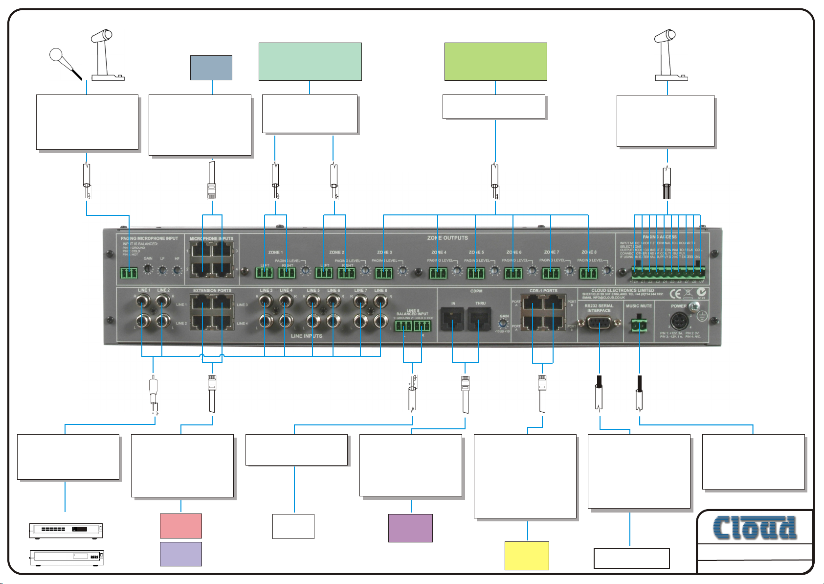
Paging microphone
Microphone input for use
with third party paging
microphones or a standard
microphone.
10dB to 50dB gain.
Microphone Inputs
4 Mic inputs for connection
to ME1 remote panels.
Connect using Cat-5e and
shielded RJ45. Level control
is at the ME1, routing can
be done at the DCM-1.
Zone Out Stereo
Two balanced stereo
outputs. Can be switched
to mono.
Zone Out Mono
Six balanced mono outputs.
Access Contacts
Short to ground access
contacts for use with
third party paging
microphones.
Line In
Stereo phono jack sockets
for connection to sources in
the same rack. Will accept
signals of ±12dBu
Extension Ports
Extensions of Lines 1-4 for
use with the LE1 and BE1
remote panels. Connect
using Cat-5e and shielded
RJ45. Treated as normal
line inputs within the mixer.
Balanced Line In.
Stereo balanced input for
line 8.
CDPM
IN socket connects to a
CDPM paging network.
THRU socket extends
CDPM paging network to a
second DCM-1 to give
16 paging zones.
CDR
Sockets for up to four
chains of CDR-1 remote
control panels.
A chain may comprise
any number of remotes,
four ports provided to
allow flexibility in cabling.
Connect using unshielded
Cat-5 and RJ45.
RS232
Full RS232 socket allows
options of control, backing
up and configuring. Use a
straight cable to connect to a
PC. Use a three core
screened cable to connect to
third party controllers.
Mute
Music mute contacts for use
with a pair of fully isolated
contacts that may be
triggered by emergency
systems.
Other manuals for DCM-1
2
This manual suits for next models
1
Table of contents
Other Cloud Recording Equipment manuals


