BRAMIDAN B3 User manual

Operating
instructions
Baler
B3 and B4
Manual no. 7995-041
Version 01-09-2018
USA- English edition


Indholdsfortegnelse USA.fmBaler B3 and B4
Table of Contents
1 EU conformity declaration ......................................................................................................... 1
2 Conditions.................................................................................................................................. 2
Explanation of symbols ...................................................................................................... 2
3 Personal Safety ........................................................................................................................ 3
4 Use and function........................................................................................................................ 5
Bale size ............................................................................................................................. 5
Worth knowing ................................................................................................................... 6
5 Transport .................................................................................................................................. 7
Lashing .............................................................................................................................. 7
Centre of gravity ................................................................................................................. 8
The baler should not be tipped over on its side ................................................................. 9
Transport using a fork-lift truck, etc. .................................................................................. 9
Transport using a crane ................................................................................................... 10
Moving an installed baler ................................................................................................. 10
6 Installation .............................................................................................................................. 11
Indoor or outdoor location ................................................................................................ 12
Clearances and working area .......................................................................................... 12
Connection ...................................................................................................................... 13
Single phase motor with socket ....................................................................................... 13
7 Cords, straps, or steel wire ..................................................................................................... 14
8 Operating principles ................................................................................................................ 15
Power interruption ............................................................................................................ 15
Emergency stop .............................................................................................................. 15
The start button ............................................................................................................... 15
Two-hand control.............................................................................................................. 15
The bale-ejection is blocked ............................................................................................ 15
Additional functions .......................................................................................................... 16
9 The Operating Panel ............................................................................................................... 17
Description ...................................................................................................................... 17
Push buttons with light signal .......................................................................................... 17
The function of the push buttons ..................................................................................... 18

Indholdsfortegnelse USA.fmBaler B3 and B4
10 Mounting cords or straps ...................................................................................................... 19
11 Filling and compression ........................................................................................................ 20
Distribution of waste ........................................................................................................ 20
Compression ....................................................................................................................20
Finishing the bale prematurely ........................................................................................ 21
Cancelling of finishing the bale prematurely .................................................................... 22
12 Binding .................................................................................................................................. 23
13 Ejecting the bale ................................................................................................................... 26
14 Maintenance ......................................................................................................................... 29
Daily check ...................................................................................................................... 29
Weekly check ..................................................................................................................29
Biannual check ................................................................................................................30
Annual check ................................................................................................................... 30
Damage to paintwork ....................................................................................................... 30
Cleaning .......................................................................................................................... 30
Spare parts ...................................................................................................................... 31
Disposal ........................................................................................................................... 31
15 Troubleshooting .................................................................................................................... 32
The bale press does not start........................................................................................... 32
The bale press cannot start and the start button is flashing ............................................ 32
The bale press is very noisy ............................................................................................ 32
The bale press cannot eject the bale ............................................................................... 33
Leakage ........................................................................................................................... 33
16 Checklist for safety check ..................................................................................................... 34
17 Electrical diagram (located in the switch case) .........................................................................
18 Hydraulic diagram (located in the switch case) ........................................................................
EF Declaration F USA.fm • Page 1Baler B3 and B4
Manufacturer: Bramidan A/S
Industrivej 69
DK-6740 Bramming
Telephone: +45 75 17 32 66
Fax: +45 75 17 31 77
Internet: www.bramidan.com EC Declaration of Conformity R205-F
Hereby declares that:
Machine: B3 and B4
Was manufactured in conformity with:
•ANSI Z245.51-2008 Balling Equipment - Safety Requirements.
•The provisions of the EU Machinery Directive 2006/42/EC with later amendments, with special reference
to Annex II, part A and Annex I of the Directive, on essential safety and health requirements in relation to
the construction and manufacture of machines.
•The provisions of the EU EMC Directive 2014/30/EC as later amended.
•Following standards:
EN 16500 Vertical bale presses, safety requirements
EN 61000-6-2 EMC
EN 61000-6-3 EMC
EN 60204-1 Electrical equipment on machines.
Model B3 B4
Type PBC PBD
Model
Type
Note:
Bramidan baler are designed to be set up as stand-alone machines, and must not be connected with other
machinery without a new risk assessment and CE marking.
The CE declaration includes all add-on products from Bramidan
The baler must not be used for compressing wet or oily material, foam rubber, or other strong expansive
materials. The baler must not be used for explosive or easily ignited waste.
I confirm the above information:
Date Technical manager
Ejnar C. Christensen
01.09.2018
2 Betingelser USA.fm • Page 2Baler
2 Conditions
It is important to read through the operating instructions before the work begins. Pay particular
attention to the safety instructions, which are intended to protect the operator. The operating
instructions are well illustrated, so you can quickly become familiar with the baler.
No special training is required. The company that uses the baler, (Hereafter called "the
company"), shall ensure that the operator has read and understood the operating instructions
and can operate the baler safely.
The quality of the baler is constantly controlled during production, and the machine will not be
supplied to a consumer until a final inspection has been carried out. If, contrary to expectation,
the product should be in any way faulty or missing any part, we request that you contact the
dealer so that the problem can be resolved immediately.
The terms of the warranty will not apply to wear and tear on wear parts in the baler, or if the parts
are deemed to have been subject to negligence or incorrect use.
The contents must not be photocopied, reproduced or translated, either wholly or in part, without
the agreement of the manufacturer.
The manufacturer declines all responsibility with regard to compensation for injury as a result of
a person disregarding the safety regulations in these instructions.
Explanation of symbols
DANGER indicates an imminently hazardous situation, which if not avoided, will result in death or
serious injury. This signal word is limited to the most extreme situations.
WARNING indicates a potentially hazardous situation, which if not avoided, could result in death
or serious injury.
CAUTION indicates a potentially hazardous situation, which if not avoieded, may result in minor
to moderate injury. It may also be used to alert against unsafe practices.
“A HAND” indicates topics to which the reader must pay special attention.
CAUTION
DANGER
WARNING
CAUTION

3 Personsikkerhed USA.fm • Page 3Baler
3 Personal Safety
It is the company's responsibility to ensure that the relevant laws and regulations of the country
are complied with for working with the baler. The company shall ensure that the operator has
read and understood the operating instructions, see chapter 2, Conditions.
Only authorized employees (18 years or older) may operate, inspect, or maintain the baler.
Only authorized employees (16-18 years) may load the baler, but not operate it.
It is the operator's responsibility to have read and understood the operating instructions so the
baler can be safely operated. It is also the operator's responsibility to perform daily inspections of
the baler. Thus, the operator must ensure that any defects are repaired, so that neither the
operator or others are exposed to danger, see chapter 14, Maintenance, Daily check.
The baler can have a relatively high centre of gravity also when the platen is lowered, and
therefore can tip during transport, see chapter 5, Transport.
Repair and servicing must only be performed by authorized personnel who possess the
necessary knowledge and understanding of the subject, see chapter 6, Installation and chapter
14, Maintenance.
Installation and connection of the baler must occur in accordance with chapter 6, Installation,
Connection.
• The baler must only be operated by one person. Only the operator should be in the vicinity of
the baler when ejection is being performed. See chapter 6, Installation, Clearances and
working area.
• The main door must be open to at least 90° before bale-ejection
• The working area must be tidy and free of waste and similar.
• The baler must not be used if the safety features are incapacitated, defective, or if it is no
longer working in any way.
• Only use cords, straps, or steel wires that are recommended by the dealer of the baler, see
chapter 7, Cords, straps, or steel wire.
CAUTION
WARNING
CAUTION
CAUTION
CAUTION
CAUTION
DANGER

3 Personsikkerhed USA.fm • Page 4Baler
• Binding with steel wire can pose a risk of tearing hands and clothes. Steel wire may be slightly
difficult to handle, since it is not so easy to bend. Therefore, exercise extra caution and
always be aware of both ends of the steel wire at the same time. We therefore recommend
using eye protection and gloves.
• When handling the bale, it is recommended that you use gloves, as there may be sharp
objects concealed in the waste.
• The baler must not be used for compressing wet or oily material, foam rubber, or other
strongly expansive materials. An example of strong expanding materials could be
plastic rolls or the equivalent, which would build up strong spring forces during
compression. Another example could be bubble wrap or anything with air trapped
inside.
• The baler must not be used with explosive or easily ignited material, see chapter 11,
Filling and compression.
• Operation of the baler must always be carried out in accordance with the local regulations for
use of technical equipment (machines), which can vary from country to country.
• It is recommended to use original spare parts.
• Avoid coming in contact with hydraulic oil through inhalation or skin contact.
• The hydraulic oil can be hotter than 70° C, and can therefore cause scalding.
• A jet from a hydraulic hose may cause serious damage to skin and eyes.
• Never climb on the baler.
CAUTION
CAUTION
WARNING
DANGER
CAUTIONWARNING
CAUTIONCAUTION
DANGER

4 Anvendelse og funktion USA.fm • Page 5Baler
4 Use and function
The baler is intended for compressing cardboard and plastic or other forms of dry waste with a
similar consistency, see the table:
Note 1: Not bundled or solid lumps, not cardboard tubes or similar.
Note 2: Only perforated bottles or cans without lids.
Note 3: Only loose sheets, not bundled or solid lumps.
If you want to compress special waste materials, please contact your dealer or the manufacturer
directly for advice beforehand to enquire whether the materials you wish to compress might
overload your press.
Important!
The baler must not be used for compressing wet or oily material, foam rubber, or other
strongly expansive materials.
An example of strong expanding materials could be plastic rolls or the equivalent, which
would build up strong spring forces during compression. Another example could be
bubble wrap or anything with air trapped inside.
Never place long items upright. Place them horizontally, or at least diagonally, in the baler.
The baler must not be used for explosive or easily ignited waste.
Bale size:
The bale size is set at the factory. The bale size can be permanently changed if necessary.
Contact the dealer for more information.
It is possible to change the bale's size individually from time to time with a single press on the
finish indicator button. See chapter 11, Filling and compression, Finishing the bale prematurely.
Waste type B3 and B4 B-series X series
Cardboard ¹●●●
Plastic in soft materials, dry (LDPE) ●●●
Plastic bottles, dry (PET) ²●
Plastic, dry (HDPE, PP, PS) ●
Plastic, dry (PVC) ●
Paper ³●●●
Plastic cans ●
WARNING
DANGER

4 Anvendelse og funktion USA.fm • Page 6Baler
Worth knowing:
The combination of solid construction and thought through safety equipment means that the
baler can always be operated safely:
• The baler's operating panel has an emergency stop, which immediately stops the baler when
activated.
• The light in the operating panel's buttons guides the operator through the different phases of
the compression, see chapter 9, The Operating Panel.
• In order to activate the start button between each press cycle, the filling door must be opened
and closed. This is due to the door switch’s monitoring of the baler, and prevents intentional
evasion of the safety system.
• The press functions are deactivated when you open the door, and can only be activated when
the doors are closed again.
• For models with automatic doors, the closing movement stops immediately and the doors
open up by returning to the starting position if something gets stuck.
• For models with ejection systems, the ejection is only operable via a two-handed operation,
where there must be a simultaneous constant pressure within a time interval of ½ second.
This ensures that the operator or others are not standing in front of the bale when it is tipped
out of the chamber. In addition, the operator has a view of the baler's working area, and can
thus ensure that others are not exposed to danger.
• The baler cannot eject the bale before the doors are open, which prevents accidental use of
the baler.
• The baler's moving parts are secured with covers.
5 Transport USA.fm • Page 7Baler
5 Transport
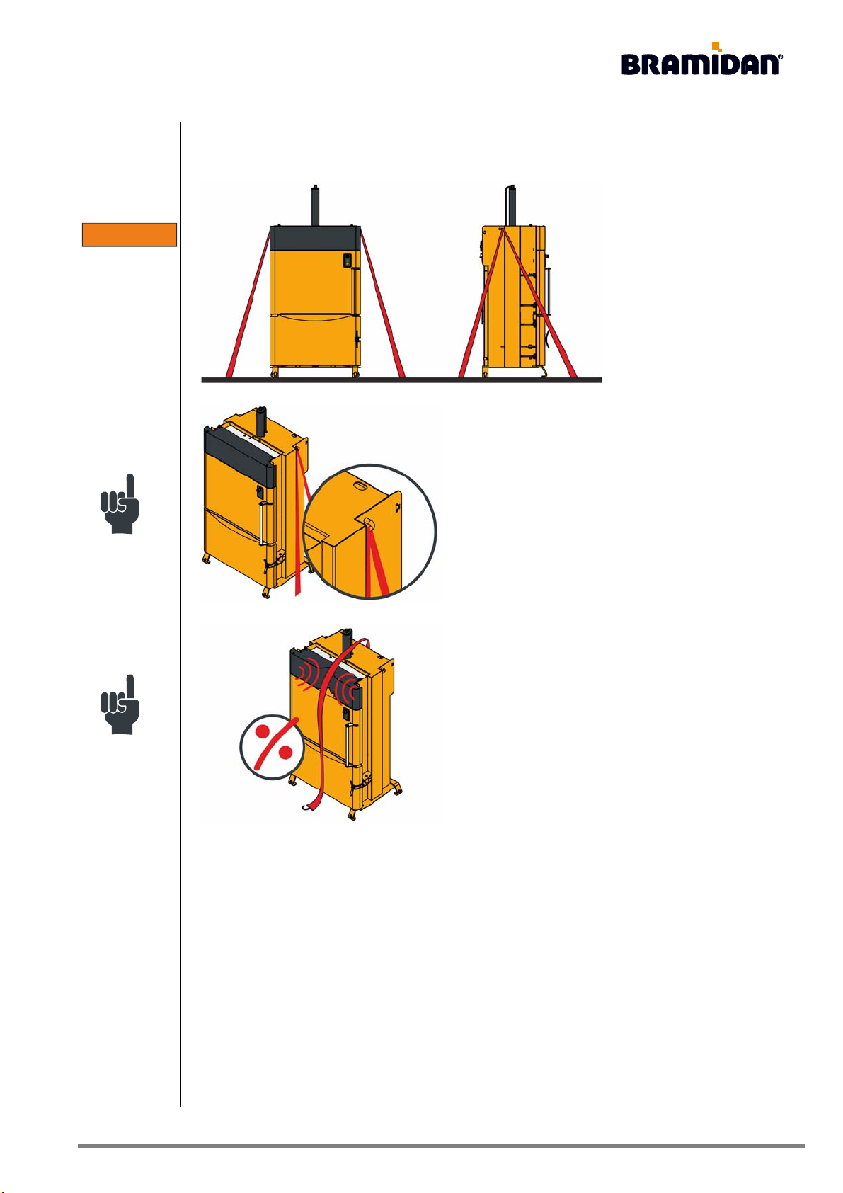
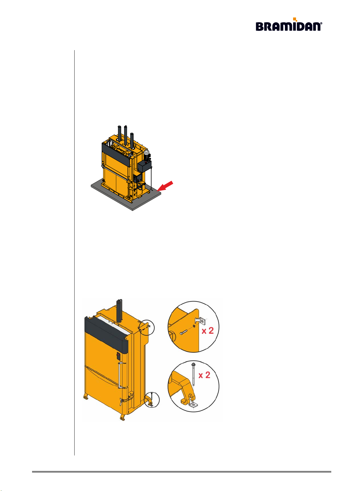
Lashing:
The baler must be securely
lashed during transport
Lashing must only take place in the lashing brackets or
in the oval slots on the baler's top frame.
Never lash over "free standing" screens that can be
deformed by the load. The screens are marked with a
warning label on the packaging.
WARNING
5 Transport USA.fm • Page 8Baler
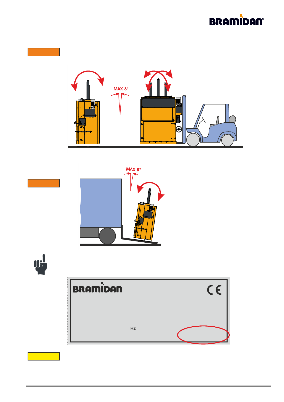
Center of gravity:
Due to the baler's relatively high centre of gravity, cautious transportation is required. The baler
must never lean more than 8° during transport.
Never lift the baler higher than strictly
necessary, and be especially aware when
transporting over sloping surfaces, such as
loading ramps. The baler must never lean
more than 8° during transport.
The lifting equipment must be designed for lifting the weight of the baler. The baler's weight
appears on the nameplate on the baler.
Always use the safety equipment required by law in connection with transport. Never lift anything
directly above people or animals.
3
7
1
5
-
2
2
9
D
Industrivej 69
DK-6740 Bramming
Tel. +45 75 173266
www.bramidan.com
kW
Volt Amp
dB
Lbs
:
:
:
:
:
:
No.
Model
Year
:
:
:
WARNING
WARNING
CAUTION

5 Transport USA.fm • Page 9Baler
The baler should not be put down on its side:
If it is necessary to put the baler down on its side, do the following:
The oil tank's original plug must be replaced with an airtight plug, so the oil does not escape.
Alternatively, the oil is drained from the system. The oil level in the tank is shown in the table
chapter 14 Maintenance, Semi-annual inspection.
When the baler is in place, it is important to mount the original plug again before the baler is
started. The airtight plug causes pressure to build up during operation, so that the oil tank cracks.
When the baler is laid on its side, attach the baler in the same way as when lifting it using a
crane. A fork-lift truck with crane hook can assist with safe tilting.
Transport using a fork-lift truck, etc.:
When using a fork-lift truck, be careful to avoid damaging spindles (hand wheels) and screens.
Spindles (hand wheels) and screens are marked with a warning label on the packaging.
When driving, the fork-lift truck must never
exceed 20 inches above the ground.
The baler's base is designed so that it can't
tip off the fork of a fork-lift truck.
CAUTION
CAUTION

5 Transport USA.fm • Page 10Baler
Transport using a crane:
When using a crane, the lifting gear must be hooked through the two holes uppermost in the
baler's top. Do not use the eye on the top of the steering rod or the oval holes on the baler's top
frame for gripping!
In models where this is not available, place a round sling around the baler's top sidepieces. Take
care that the round sling does not deform the brackets on the vertical door.
Moving an installed baler:
All parts must be removed, and the chamber must be empty of material and other loose items.
The platen must be brought all the way down to the bottom position, so the center of gravity is
moved as far down as possible. This is done by pressing on the green start button for a minimum
of 3 seconds.
WARNING
6 Installation USA.fm • Page 11Baler
6 Installation
The baler fulfils the applicable EU requirements on electromagnetic interference, and may be
installed in both residential and industrial environments.
The baler's noise level is initially less than 70dBA. If the baler's noise level exceeds 70dBA, this
will appear on the nameplate on the baler.
The noise level is measured based on an operator's position during the baler's operation, about
39 inches from the operation and at a height of 63 inches.
In order to reduce vibrations that may occur during
operation, the baler can be placed on a thick, soft rubber
mat.
The baler is designed for temperatures between 32-95 Fahrenheit and a humidity of between 10-
90%.
• When installing in colder environments, a special artic oil shoud be used (optional
equipment).
• When installing in warmer environments, a cooling system should be mounted on the
hydraulic system (optional equipment).
For B3: The baler must always be mounted to the floor or wall.
Use the mounting brackets supplied.
6 Installation USA.fm • Page 12Baler
Indoor or outdoor location:
The baler is designed to be indoors in a dry room on a flat, stable floor.
If the baler is placed on, for example, wood flooring, horizontal divisions, etc., the baler's own
weight, plus the weight of the compressed waste must be taken into account.
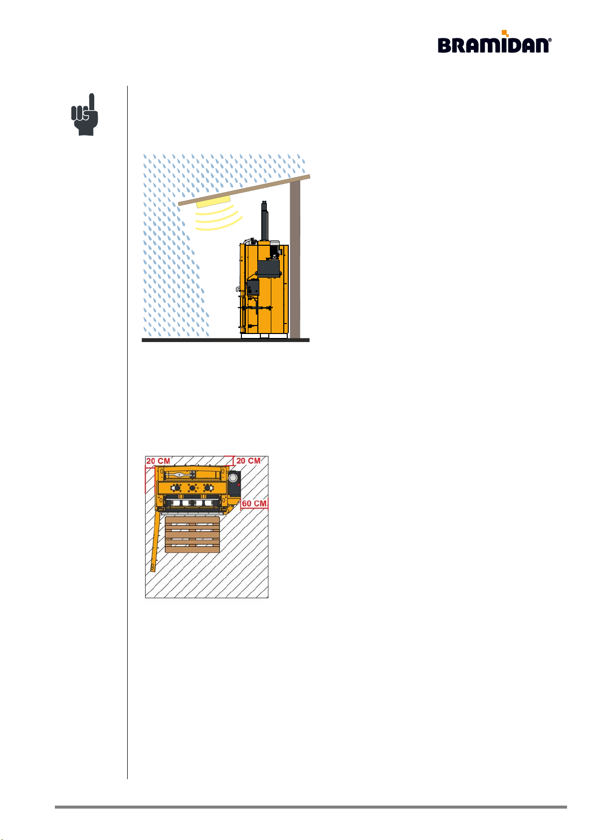
If the baler is placed outdoors, the baler must at least be
placed under a canopy. The canopy should be able to
protect the baler from all types of precipitation, such as
driving rain.
With outdoor placement, you must expect a reduction of
the baler's lifespan as well as the need for more frequent
servicing.
Take care to ensure there are suitable lighting
conditions, so that working with the baler can take place
without danger.
Clearances and working area:
The baler is placed so that it is possible to replace the binding material behind the chamber on
certain models. The baler's left side should be placed at least 8 inches from the wall, so the doors
can be opened the necessary 90°.

6 Installation USA.fm • Page 13Baler
The working area must be tidy and free of waste and similar.
Connection:
Before the baler is connected to the supply network, check whether the electric motor is single or
three phase. This appears on the nameplate on the baler. If the motor is single phase, it will say,
for example 1x230 Volt under "Supply", and if the motor is three phase, it will say, for example,
3x400 Volt.
The voltage of the supply network must be appropriate for the configuration of the baler.
Important!
The electrical earthing in the machine must be used and is connected to the fixed installation.
Single phase motor with socket:
Before connecting the baler you must visually ensure that the supply network looks secure, and
that there are no defects, loose parts, etc.
The socket replaces the repair switch in accordance with applicable rules. Therefore, there must
always be easy access to the socket, so the power can be interrupted again.
3
7
1
5
-
2
2
9
D
Industrivej 69
DK-6740 Bramming
Tel. +45 75 173266
www.bramidan.com
kW
Volt Amp
dB
Lbs
:
:
:
:
:
:
No.
Model
Year
:
:
:
CAUTION
CAUTION

7 Snor, bånd eller ståltråd USA.fm • Page 14Baler
7 Cords, straps, or steel wire
The composition of the bale and the baler’s press pressure determine what type of cords, straps
or steel wire can be used.
Choice of cords, straps, or steel wire can be crucial for further handling of the bale. It is therefore
advisable to contact the purchaser to hear about any possible benefits.
If you want to use steel wire for binding the bale, some balers must first be readjusted for this,
see chapter 10, Mounting cords, straps or steel wire.
Contact any dealer of the baler or supplier of cords, straps or steel wire for more information.

8 Funktionsprincipper USA.fm • Page 15Baler
8 Operating principles
Power interruption:
If power to the bale presser has been disconnected, the baler must be reset with a single push of
the green start button. If this occurs during ejection of the bale, continue the process by pressing
the two orange finish indicator buttons, which together constitute two-hand control. The buttons
only light while being pressed.
Emergency stop:
If the emergency stop has been activated, it must be deactivated, after which the baler must be
reset with a single push of the green start button.
Start button:
In order to activate the start button between each press cycle, the filling door must be opened
and closed. This is due to the door switch’s monitoring of the baler, and prevents intentional
evasion of the safety system.
Two-hand control:
The two-hand control requires a simultaneous, constant pressure within a time interval of ½
second.
The bale ejection is blocked:
There must not be any materials jammed in the ejection system, since this will prevent the press
from ejecting the bale. The ejection mechanism on the platen must be pushed completely
forward, if it is pushed back, the jammed material must first be removed.

8 Funktionsprincipper USA.fm • Page 16Baler
Additional functions:
The following functions are not installed when the machine leaves the factory, and require an
adjustment of the actual control system. Contact the dealer for more information.
Automatic start:
The baler starts when the filling door is closed, and it is therefore unnecessary to start it by
activating the green start button.
Multiple press cycles after each start:
When the baler is activated, the platen runs the required number of press cycles.
Pause in the top position:
The platen remains in the top position for the required length of time. There is no reason for this
except when running with more than one cycle or for testing.
Pause in the lowest position:
The platen remains in the lowest position on the bale for the required length of time. This function
can be used when it is known how frequently the baler is used, and an alternative is required to
parking the platen on top of the bale (occasionally or permanently).
Parking the platen on the bale (permanent solution):
If you want a permanent solution where the platen parks on top of the bale every time in order to
hold the pressure, for instance on expanding materials, the baler can be run with half press
cycles.
To park the platen on the bale (occasionally) see chapter 9 The Operating Panel.
This manual suits for next models
1
Table of contents


