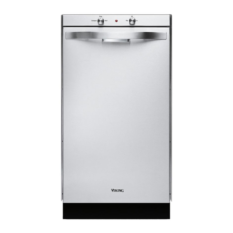
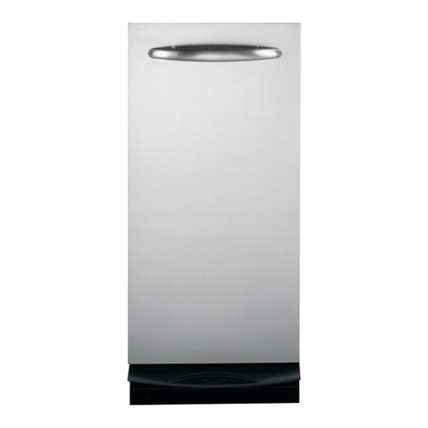
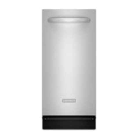
Viking FCU150 User manual

Viking Range Corporation
111 Front Street
Greenwood, Mississippi 3 930 USA
(662) 455-1200
For product information,
call 1- -VIKING1 ( 45-4641)
or visit the Viking Web site at
vikingrange.com
F20 32 EN (99527615B)
Trash Compactor
Viking Installation Guide &
Use & Care Manual

IMPORTANT–Please Read and Follo !
3
Site Preparation It is recommended that a thorough site inspection be
conducted PRIOR to unpacking and moving this appliance.
WARNING
Make su e that incoming voltage is the
same as unit ating. An elect ic ating
plate specifying voltage, he tz, and amps
is attached to the p oduct. Wi ing the
compacto with mo e voltage than it is
ated fo may cause seve e damage. To
educe the isk of fi e, elect ic shock, o
inju y to pe sons, installation wo k and
elect ical wi ing must be done by qualified
technician in acco dance with all
applicable codes and standa ds, including
fi e- ated conditions.
• Before beginning–please read these
instructions completely and carefully.
•DO NOT remove permanently affixed
labels, warnings, or rating plates from the
trash compactor. This may void warranty or
create an unsafe product.
• Please observe all national and local
codes.
• Please ensure that this product is properly
grounded.
• The installer should leave these
instructions with the consumer who should
retain for local inspector’s use and for
future reference.
Table of Contents
Warnings & Important Information ______________________________________ 3
Dimensions __________________________________________________________ 5
Specifications ________________________________________________________ 6
Cutout Dimensions ___________________________________________________ 7
Electrical Requirements _______________________________________________
General Information __________________________________________________ 9
Installation __________________________________________________________ 10
Panel Installation and Dimensions______________________________________ 11
Accessory Door Panel (PTDP15) ____________________________________ 11
Accessory Door Panel (PDTP1 ) ____________________________________ 12
Custom Door Panel _______________________________________________ 13
How the Compactor Works ___________________________________________ 14
Operation___________________________________________________________ 15
Key Lock Switch __________________________________________________ 15
Clock/Auto Delay _________________________________________________ 15
Battery Backup ___________________________________________________ 15
Preparing Odor Control Disk _______________________________________ 16
Installing Odor Control Disk________________________________________ 16
Installing Bag_____________________________________________________ 17
Compacting______________________________________________________ 17
Compacting Tips _________________________________________________ 17
Bag Removal _____________________________________________________ 1
Cleaning____________________________________________________________ 19
Troubleshooting _____________________________________________________ 20
Service & Registration ________________________________________________ 21
Warranty____________________________________________________________ 22
2
WARNING
DO NOT put paint, oily ags, lighte fluid cans,
paint thinne cans, etc., in you compacto . Doing
so could esult in spontaneous combustion causing
a fi e and/o explosion.
CAUTION
NEVER push t ash into the bucket with hands o
feet. T ash might contain b oken glass, sha p
pieces of metal, etc., which could cause inju y.
CAUTION
Glass f agments and othe sha p t ash pieces
may be on o a ound the su faces to be cleaned.
Ca efully emove these objects befo e wiping
down any su faces.
WARNING
DO NOT compact ae osol cans o any othe
containe s still holding o which held toxic
chemicals, insecticides, o combustible contents.
Fumes may be e eleased that a e haza dous to
health o may esult in fi e o explosion.
CAUTION
The odo cont ol disk contains mate ial that may
cause mode ate eye i itation. Avoid contact with
eyes. Ha mful if swallowed. Wash skin o clothing
tho oughly with soap and wate afte handling.
DO NOT euse empty foil pouch.

54
IMPORTANT–Please Read and Follo !
READ ALL INSTRUCTIONS CAREFULLY
BEFORE OPERATATING COMPACTOR.
Basic precautions shoul always be taken
when using an electrical appliance –
inclu ing the following:
• Close supervision is necessary when any
appliance is operated near children.
DO NOT allow the appliance to be used
as a toy, or to run unattended at any time.
Turn key to “OFF” and remove it to lock
the compactor. Store the key out of reach
to prevent children or others from
operating or tampering with the
compactor.
•DO NOT push trash into compactor
drawer with hands or feet. Trash might
contain broken glass, sharp pieces of
metal, etc., which would cause injury.
•DO NOT compact volatile material. Paint,
oily rags, lighter fluid cans, and paint
thinner cans could combust spontaneously
and cause an explosion and/or fire.
•DO NOT compact aerosol cans or any
other containers still holding toxic
chemicals, insecticides, or combustible
contents. Fumes may be released which
are hazardous to health.
•DO NOT compact lighted cigarettes,
cigars, or other hot or burning items.
•DO NOT overload the compactor.
• Be careful when removing and carrying
bag. Broken glass or other sharp objects
may pierce bag. DO NOT overload trash
bag with heavy material such as glass.
•DO NOT operate this unit with an
extension cord.
• Use only Viking approved accessories.
•DO NOT touch moving parts.
•DO NOT take this appliance apart.
Incorrect reassembly can cause electrical
shock when operated.
•DO NOT operate with a damaged power
cord, plug, motor, or after damage of any
kind. Have the compactor examined, and
all repairs made, by an authorized
serviceman.
• This compactor is FOR HOUSEHOLD USE
ONLY. Use it only as described in this
manual.
• Unplug the appliance from outlet before
servicing.
Dimensions
*NOTE: Not including handle.
14-7/8”
(37.8 cm)
21-1/8”*
(53.7 cm)
34-1/8”
(86.7 cm)

15” W
22” D
Electrical
Outlet
12” min.
34-1/2” H
6 7
Specifications
Trash Compactor
Description FCU150
Overall width 14-7/ ” (37. cm)
Overall height from floor 34 1/ " min. to 35 1/ " max.
Overall depth from rear 21-1/ ” (53.7 cm) Does not include accessory door panel
Cutout width 15” (3 .1 cm)
Cutout height 34-1/2” ( 7.6 cm) min.
Cutout depth 22” (55.9 cm)
Electrical requirements 5.0 amps, 120VAC/60 Hz;
6’ (1. 2 m) electrical cord 3 prong plug supplied with unit
Approximate shipping weight 165lbs. (75kg)
Cutout Dimensions
The compactor requires a minimum under-
counter cutout opening 15” wide, 34½”
high, and 22” deep.
Plan to provide an electrical outlet in the
opening that meets all applicable electrical
codes and requirements. See “Electrical
Requirements” section on Page for specific
information.

Electrical Requirements General Information
9
GROUNDING INSTRUCTIONS
Importatant: TO REDUCE THE RISK OF
ELECTRIC SHOCK - Please rea carefully.
FOR PERSONAL SAFETY, THIS APPLIANCE
MUST BE PROPERLY GROUNDED. The
power cord on this appliance is equipped
with a three-prong (grounding) plug which
mates with a standard three-prong
(grounded) receptacle as illustrated above.
If there is a two-prong outlet located where
you will install the compactor, it is your
responsibility to have it replaced with a
properly grounded three-prong wall
receptacle. No adapter shall be used with
this product.
DO NOT, UNDER ANY CIRCUMSTANCES,
CUT OR REMOVE THE THIRD (GROUND)
PRONG FROM THE POWER CORD PLUG.
The GREEN (or GREEN & YELLOW)
conductor in the cord is the grounding wire.
Never connect the GREEN (or GREEN &
YELLOW) wire to a live terminal.
A 120 volt, 60 Hz., A.C., 15 amp fused and
grounded electrical supply is required
(time-delay fuse or circuit breaker is
recommended). It is recommended that a
SEPARATE CIRCUIT serving only this
appliance be provided.
DO NOT USE AN EXTENSION CORD WITH
THIS APPLIANCE.
UNPACKING THE COMPACTOR
The trash compactor is shipped from the
factory with packing material in the trash
bucket and the ram in the down position.
The ram will return to the up position once
the cord is plugged into an electrical outlet.
Open the trash bucket and remove the
packing material.
The compactor is only configured for built-in
installations.
Your compactor has four adjustable levelers;
(2) rollers in the rear and (2) legs in the front.
They allow you to adjust for uneven floors
and also trim the unit up to fit an under-
counter installation.

Installation
Top of
Compactor
Front of
Compactor
4
Fasten the slotted end of the straps to the compactor
using the holes in the top of the compactor cabinet
as shown.
NOTE: When installing compactor under granite or
solid-surface countertops, bend the mounting straps so
they can be secured to the adjacent cabinetry.
Back of
Compactor
Slots
Rollers
Wood
Block
Adjusting
Screws
1
Leveling
Legs
Front of
Compactor
Wood
Block
2
Tip the front of compactor up and onto a wood
block. Turn the leveling legs in or out to the desired
position. Remove the wood block.
Cord
Clamp
3
Use the cord clamp to prevent excess power cord from
being pinched beneath the cabinet during installation
or service.
Tip the back of compactor up and onto a wood block.
Loosen the adjusting screws only far enough to move the
rollers to a higher or lower slot. Retighten the adjusting
screws and remove the wood block.
Panel Installation and Dimensions
ACCESSORY DOOR PANEL (PTDP15)
The following installation parts are supplied
with PTDP15 door panels:
• Accessory door panel with foam insert
(finish designates color)
• Foam insert
• 5 – # sheet metal screws
Accessory Door Panel Installation (PTDP15)
The PTDP15 panel will be held on by five
screws (supplied in door panel packaging)
and two screws with locator pins pre-
attached (supplied on panels).
1. Remove all plastic covering on the
stainless steel panel.
2. Place the panel onto the outside of the
door, aligning it with the pre-drilled holes
on the trash compactor door facing.
3. Insert the panel into the door by inserting
the pre-attached locator pins into the
middle screw hole (second hole from top
on left and right-hand sides).
4. Install the five screws provided with
packaging into their designated locations
(two on left, two on right, and one at the
top).
14-3/4"
(37.5 cm)
8"
(20.3 cm)
30-7/16"
(20.3 cm)
6"
(15.3 cm)
6"
(15.3 cm)
Locator
Pin
Locator
Pin
Locator
Pin
Locator
Pin
Locator
Pin
Locator
Pin
7"
(17.8 cm)
10 11

ACCESSORY DOOR PANEL (PTDP1 )
The following installation parts are supplied
with PTDP1 door panels:
• Accessory door panel with foam insert
(finish designates color)
• 2 – Accessory side trim pieces
• 13 – # Sheet metal screws
Accessory Door Panel Installation (PTDP1 )
The PTDP1 panel will be held on by five
screws (supplied in door panel packaging)
and two screws with locator pins pre-
attached (supplied on panels).
1. Remove all plastic covering on the
stainless steel panel.
2. Place the panel onto the outside of the
door, aligning it with the pre-drilled holes
on the trash compactor door facing.
3. Insert the panel into the door by inserting
the pre-attached locator pins into the
middle screw hole (second hole from top
on left and right-hand sides).
4. Install the five screws provided with
packaging into their designated locations
(two on left, two on right, and one at
the top).
5. Before installing the trash compactor into
its cutout, the side trim pieces must be
attached to the unit on each side. Please
refer to the template included in your
packaging and insert four screws in the
designated locations on the left and right
sides of the unit. You will be drilling
directly into the unit to attach the trim
pieces.
17-3/4"
(45.1 cm)
7"
(17.8 cm)
8"
(20.3 cm)
30-7/16"
(20.3 cm)
6"
(15.3 cm)
6"
(15.3 cm)
Locator
Pin
Locator
Pin
Locator
Pin
Locator
Pin
Locator
Pin
Locator
Pin
CUSTOM DOOR PANEL
A custom panel of wood or other material
not exceeding 15 lbs. can be attached to
the door.
To create an attach a custom panel:
• Panel width: 15”W. = 14-7/ ” (37.9 cm);
1 ”W. = 17-7/ ” (45.4 cm)
• Panel height: 30-5/16” (77.0 cm)
• Panel thickness: 3/4” (1.9 cm)
1. Purchase an accessory handle kit to match
your cabinet hardware and install per
handle instructions. Or you may purchase
a Viking handle kit: For a 15”W. panel use
Viking PHK14SS and for an 1 ”W. panel
use PHK17SS. Drill pilot holes for wood
screws. Use drill stop to prevent drilling
through the panel.
3. Mount panel to door by using wood
screws or supplied panel mounting
screws.
4. Make sure the door opens and closes
smoothly with the actuator entering and
exiting the door interlock switch on the
compactor.
Panel Installation and Dimensions
18"W=17-7/8"
(45.4 cm)
15"W=14-7/8"
(37.9 cm)
30-7/16"
(77.0 cm)
3/4"
(1.9 cm)
7"
(17.8 cm)
7"
(17.8 cm)
12 13
Panel Installation and Dimensions
Other manuals for FCU150
2
Table of contents
Other Viking Trash Compactor manuals

Viking
Viking Designer DUC180 User manual

Viking
Viking Designer Series User manual

Viking
Viking Professional VUC181 Service manual

Viking
Viking Professional VUC181 User manual

Viking
Viking FCU150 Installation guide

Viking
Viking FCU150 User manual

Viking
Viking Designer DFC180 User manual

Viking
Viking F1213F User manual

Viking
Viking Designer DUC180 User manual

Viking
Viking Designer DFC180 User manual