BrandMotion AVMS-3701 User manual

! INSTALLATION!INSTRUCTIONS!
AVMS-3701 Instructions 7-22-16 Page 1 of 28
2007-Current Jeep Wrangler 360º System for
Factory Display Radios
(Kit # AVMS-3701)
Please read thoroughly before starting installation and check that kit contents are complete.
Items Included in the Kit:
Tools & Supplies Needed:
Factory display radio interface
Interface Video/Power harness
360º camera module
Key box power/image buttons
Rear camera and Front camera
Front lower bumper mount and harness
Rear spare tire adjustable camera mount
2 side mount cameras w/pods and harnesses
2 video output RCA cables
Power/camera input harness
2 side camera templates
Mounting screws and gaskets
These instructions
Wire strippers
Wire cutters
Electrical tape
Zip ties
Plastic panel removal tools
Digital Volt Meter / BCM safe test light
Screwdriver
Socket set
Wrench
Uni Bit / Step Bit
Drill
Safety Precautions:
•Work in well ventilated area that is clear of obstructions.
•Secure vehicle with tire chucks in both front and rear of tires.
•Turn vehicle accessories OFF and ensure ignition key is in OFF position.
•Wear safety goggles and snug fitting clothes.
•Use tools only for their intended purpose and which are in good repair.
•Only perform this task if confidence, skill, and physical ability permit.
! INSTALLATION!INSTRUCTIONS!
AVMS-3701 Instructions 7-22-16 Page 2 of 28
DUE TO THE COMPLEXITY OF THIS KIT
PROFESSIONAL INSTALLATION IS REQUIRED
CALIBRATION KIT IS REQUIRED FOR FINAL PROGRAMMING
NOTE: We strive to provide accurate and up-to-date installation instructions. For the latest full color
instructions, as well as an installation video, please visit www.brandmotion.com
REAR CAMERA INSTALL
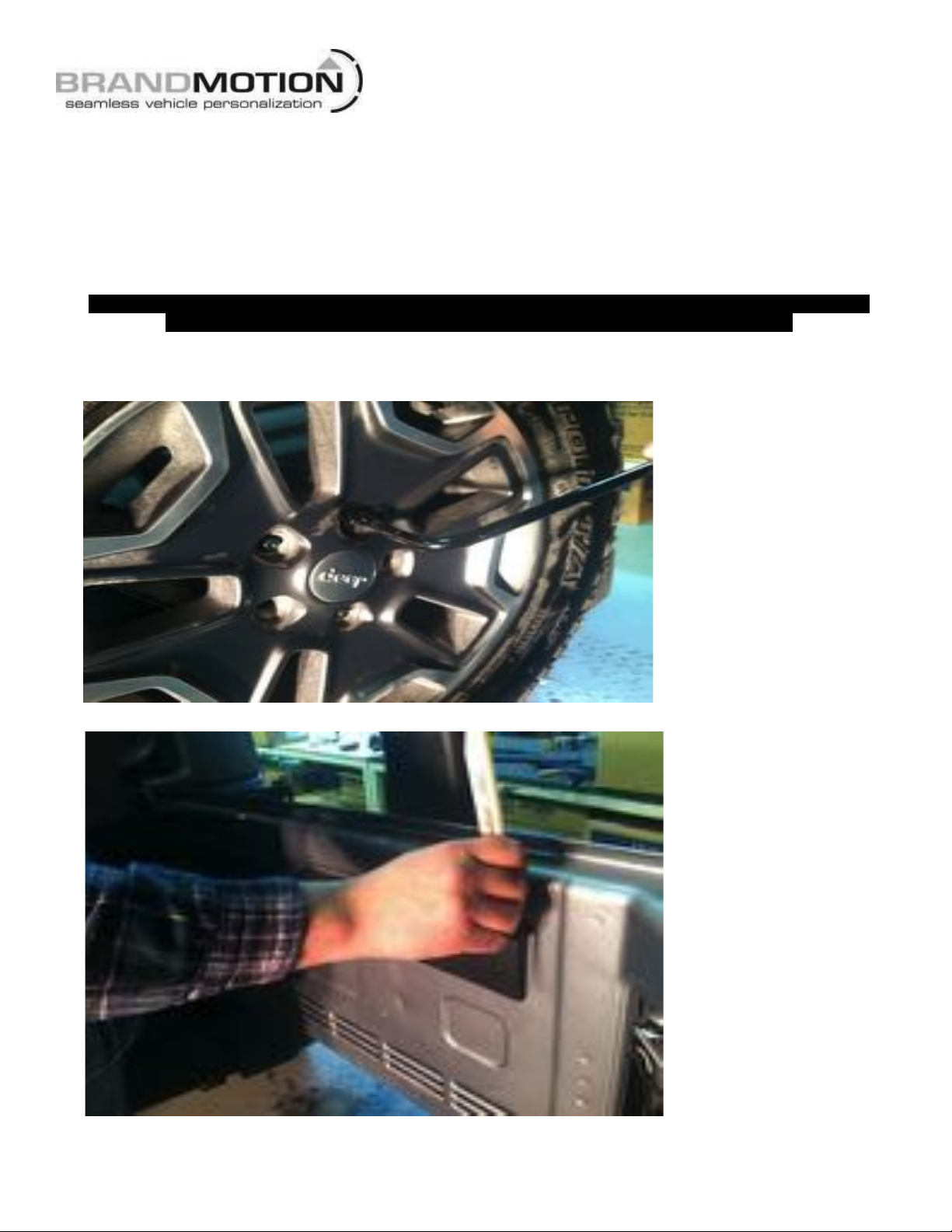
1. Remove the spare tire off of the carrier. (Use caution when removing tire.)
2. Open rear gate and remove trim from inside of gate by using plastic panel removal tool.

! INSTALLATION!INSTRUCTIONS!
AVMS-3701 Instructions 7-22-16 Page 3 of 28
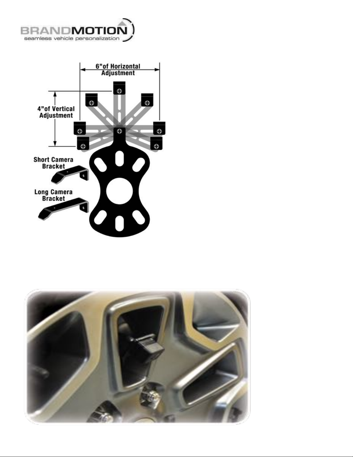
3. Mount the bracket on the rear tire mount, after bracket is on, slide on the 3 push nuts over the studs.

! INSTALLATION!INSTRUCTIONS!
AVMS-3701 Instructions 7-22-16 Page 4 of 28
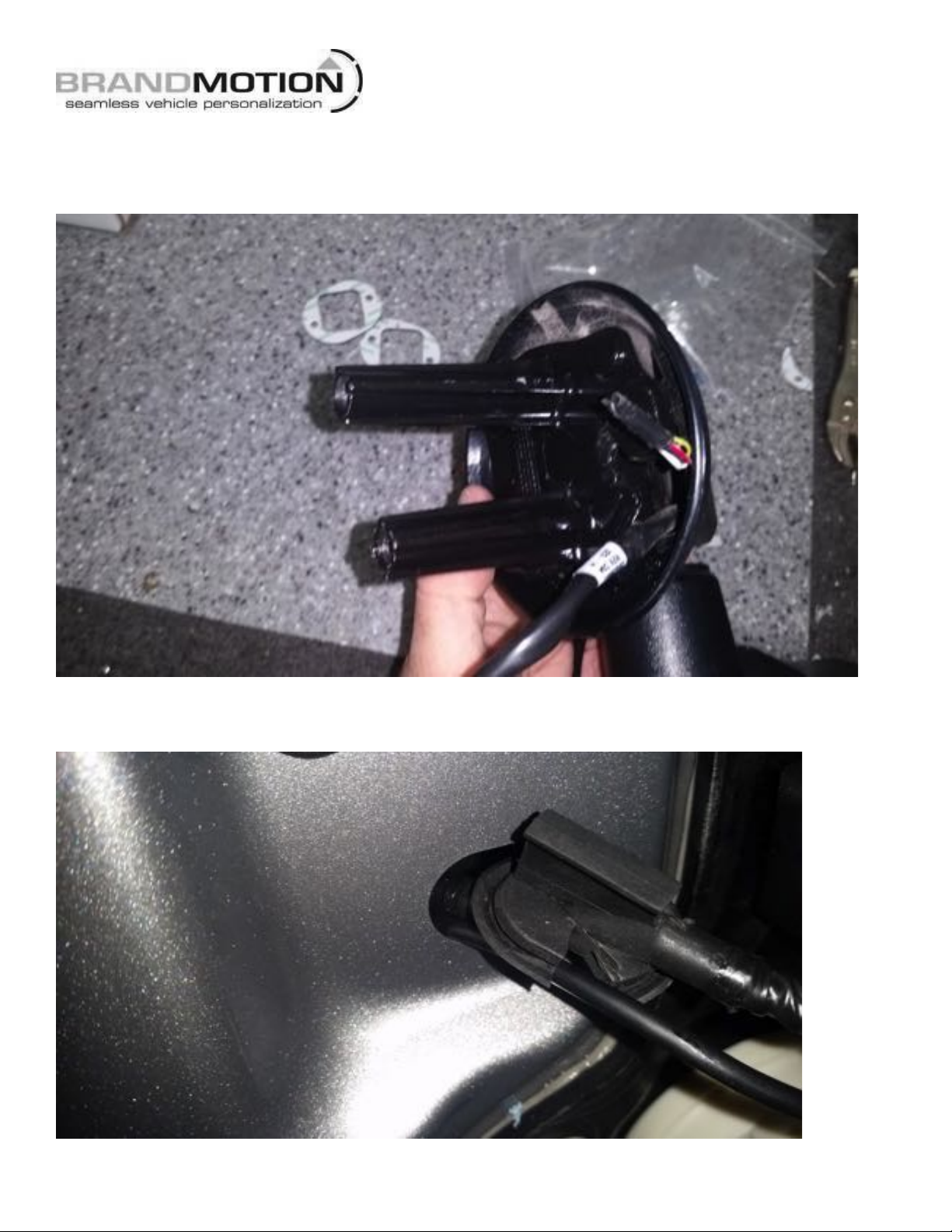
4. Run the harness into the rear gate through the factory grommet.
5. Run rear camera harness through top hole of tire carrier.
! INSTALLATION!INSTRUCTIONS!
AVMS-3701 Instructions 7-22-16 Page 5 of 28
Adjustment Bracket for Camera Clearance using Phillips Screwdriver and 3/8” Wrench or Socket Drive
Note: Short Bracket has been designed for Factory offset wheels. Use the Long Bracket for wheels with larger
offsets.
6. Remount spare tire on carrier. (MAKE SURE NOT TO PINCH THE CAMERA HARNESS.)
! INSTALLATION!INSTRUCTIONS!
AVMS-3701 Instructions 7-22-16 Page 6 of 28
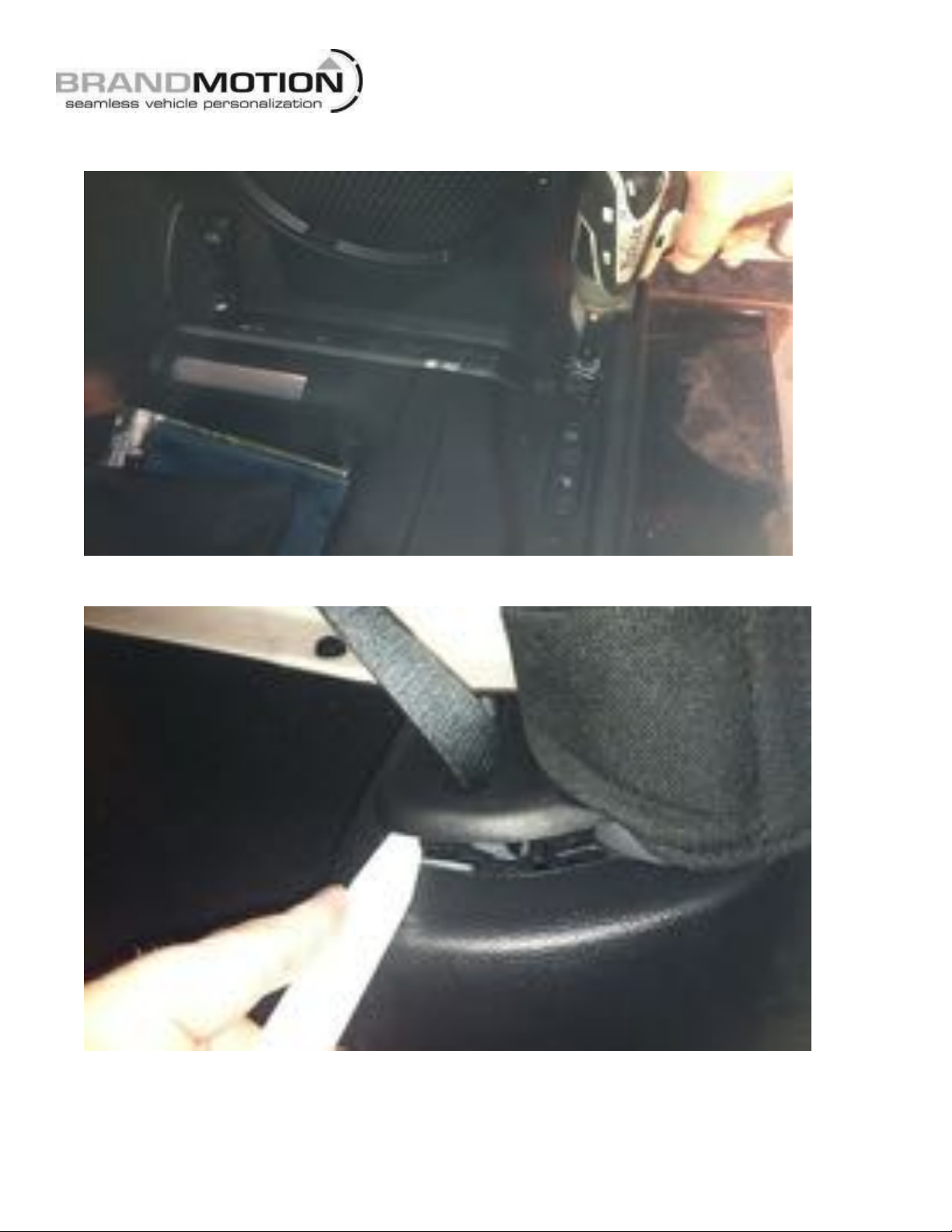
7. Use a T20 Torx bit to remove subwoofer box. (If equipped with subwoofer box.)
8. Using a plastic trim removal tool, pry off rear seat belt closeout.

! INSTALLATION!INSTRUCTIONS!
AVMS-3701 Instructions 7-22-16 Page 7 of 28
9. Using a plastic trim removal tool, remove rear access panel to expose 10mm bolt, and remove bolt.
10. Run the rear camera harness alone the factory harness. Use zip ties to secure to the factory harness.
11. Run the camera harness through the factory cloth door boot, use a long zip tie or a fish tape.

! INSTALLATION!INSTRUCTIONS!
AVMS-3701 Instructions 7-22-16 Page 8 of 28
12. Finish running the harness to the front glove box area on the passenger side of the vehicle. Coil any
excess harness and place in passenger kick panel area.
13. Remove the glove box to gain access to the back side by pressing the side of the inter glove box towards the
center to release the side stops. Then open the glove box all the way to the floor and lift up and out.
! INSTALLATION!INSTRUCTIONS!
AVMS-3701 Instructions 7-22-16 Page 9 of 28
SIDE CAMERA INSTALL
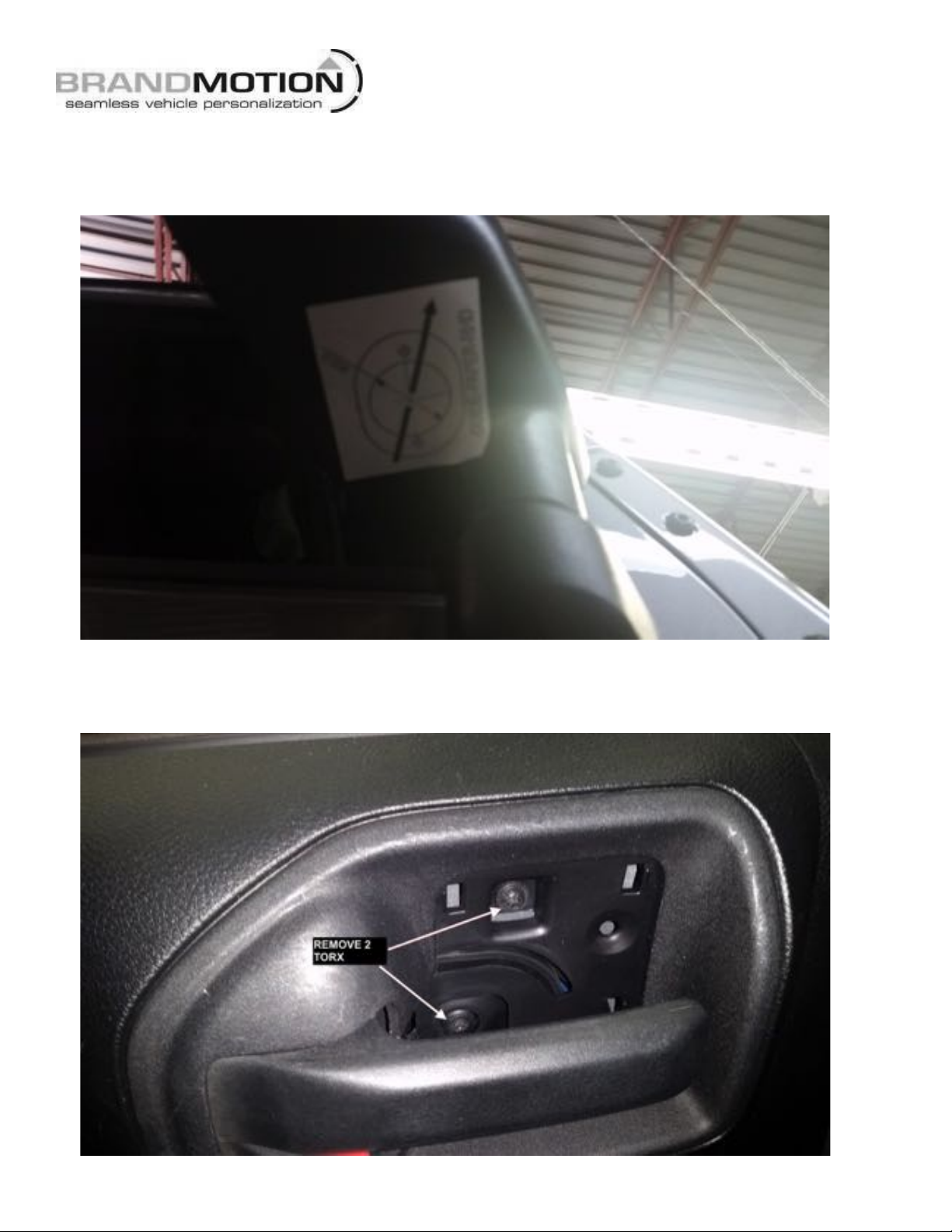
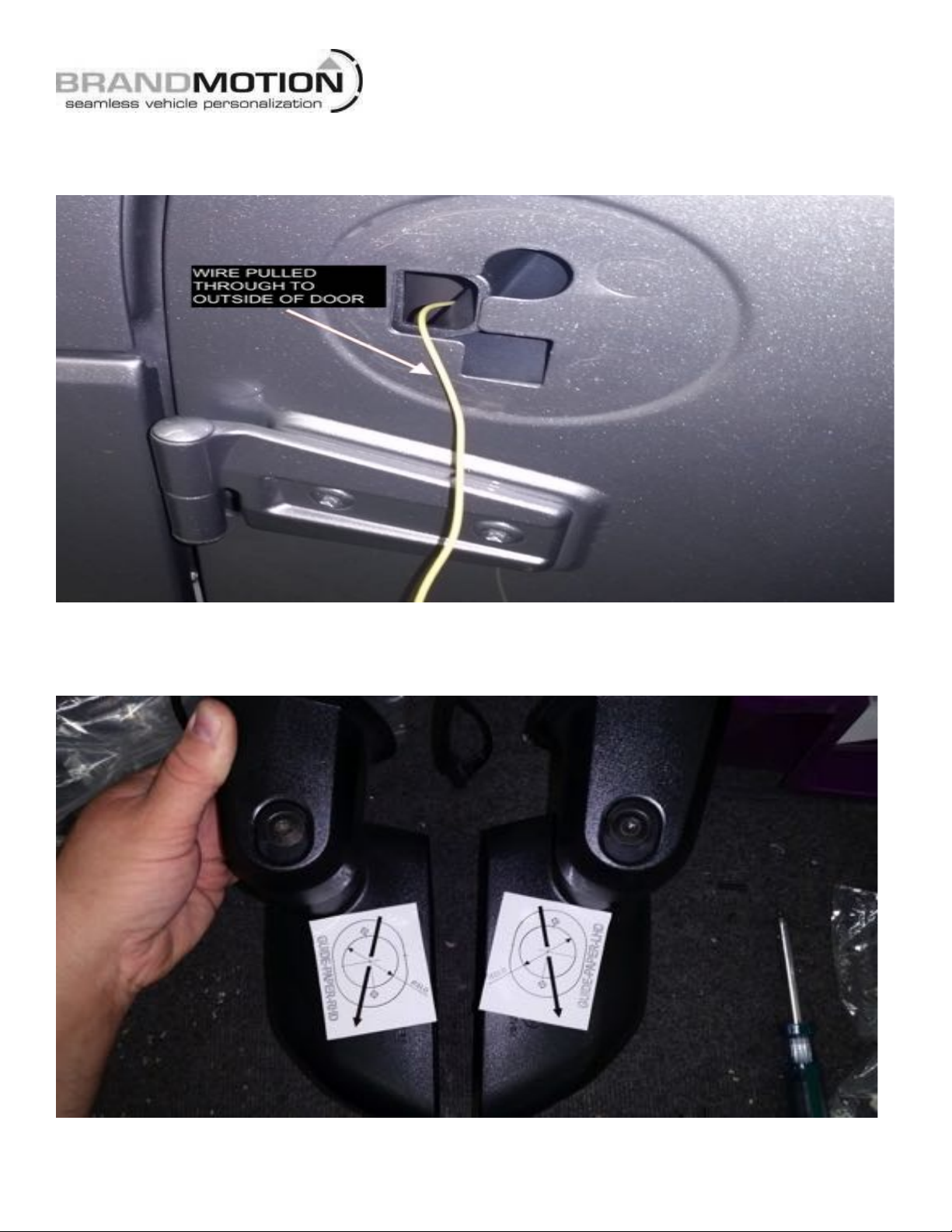
1. Place template stickers under the side mirrors. The arrow should be perpendicular to the vehicle body,
pointing away for the vehicle.(Or use the plastic guides for the correct mounting postions.)
2. Repeat for other side mirror as well.
3. Remove the door panel from the vehicle, remove trim behind door handle and remove the torx screw.

! INSTALLATION!INSTRUCTIONS!
AVMS-3701 Instructions 7-22-16 Page 10 of 28
4. Remove the inter trim on the pull handle to gain access to the two screws behind the trim.
5. Remove the (2) Torx in the lower front of the door.
! INSTALLATION!INSTRUCTIONS!
AVMS-3701 Instructions 7-22-16 Page 11 of 28
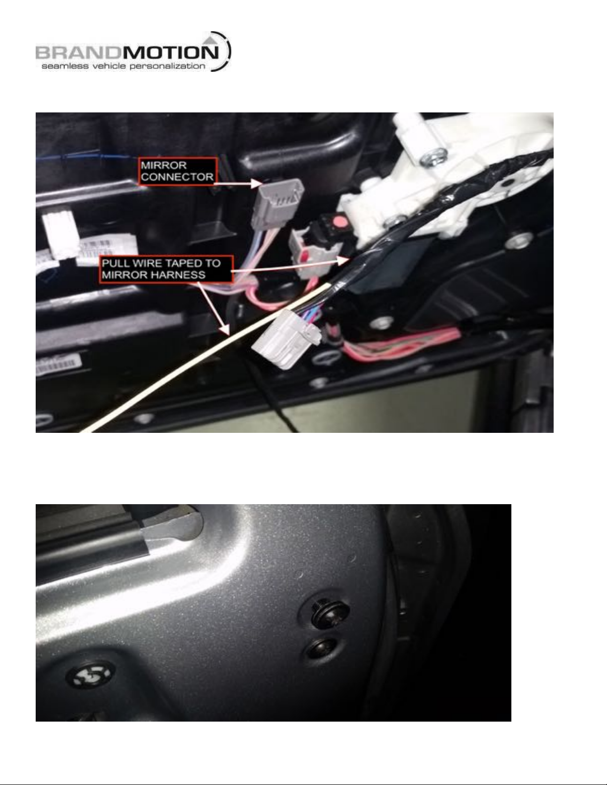
6. With the door panel removed, unplug the mirror harness and connect a pull wire to be able to pull the
harness back through the door.
7. Remove (2) Torx bolts on the inner door frame to remove mirror. (When the bolts are taken out, the
mirror might fall, hold on to the mirror while doing this.)
! INSTALLATION!INSTRUCTIONS!
AVMS-3701 Instructions 7-22-16 Page 12 of 28
8. Remove the mirror and pull harness through the door.
9. Repeat for the other side.
10. Compare the mirrors to see it the templates are in the same place and same angle on both.

! INSTALLATION!INSTRUCTIONS!
AVMS-3701 Instructions 7-22-16 Page 13 of 28
11. Remove the (3) Torx screws from inside the mirror. You can fairly easy get behind the mirror glass to do this. (The
picture show the glass already removed to show location of the screws).

! INSTALLATION!INSTRUCTIONS!
AVMS-3701 Instructions 7-22-16 Page 14 of 28
12. Remove the mirror glass by gently lifting on the plastic tabs holding the glass to the mirror motor.
13. Drill the hole in the template for the camera and the (2) mounting screws.
! INSTALLATION!INSTRUCTIONS!
AVMS-3701 Instructions 7-22-16 Page 15 of 28
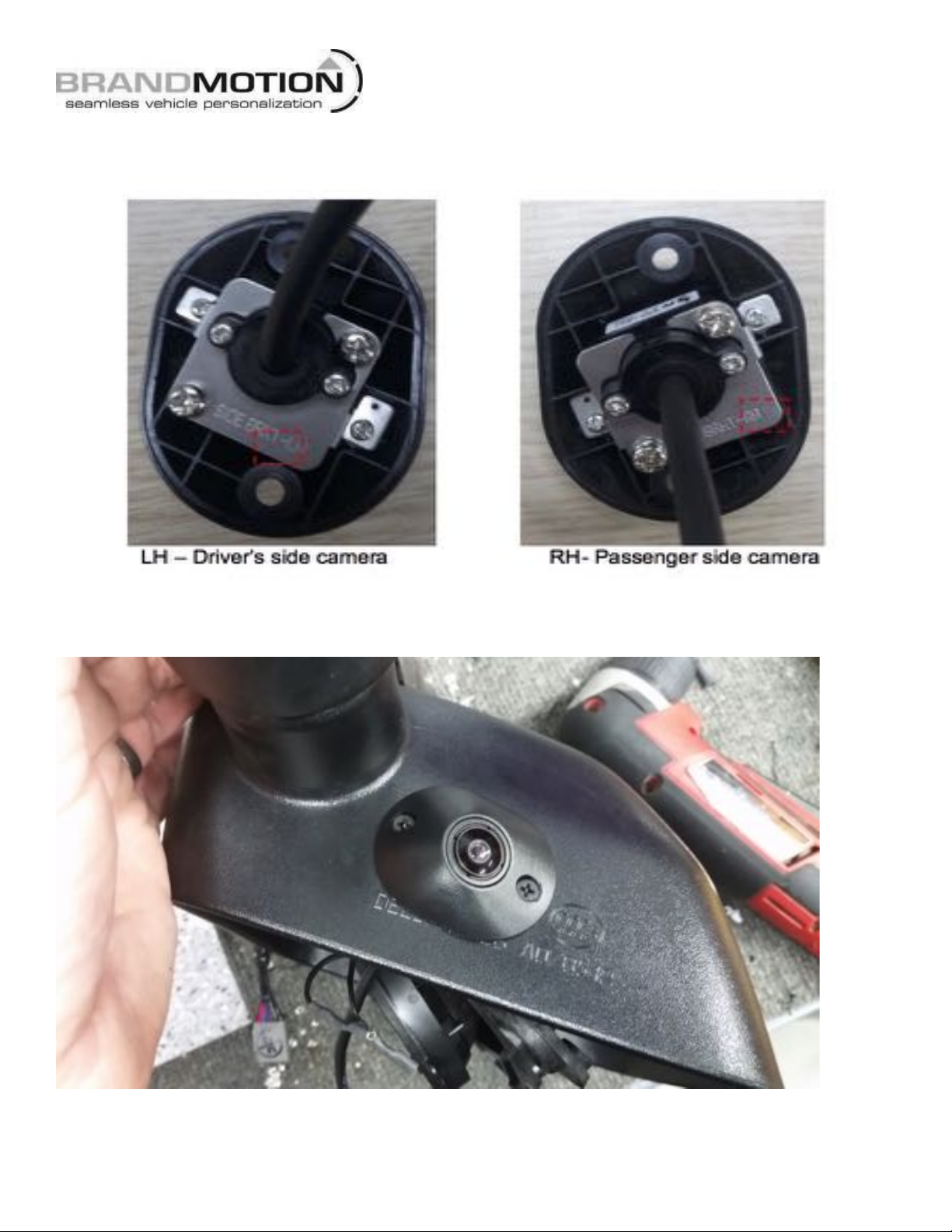
14. Mount the left camera (the camera metal bracket will have a LH stamped on it) in the side mirror pod
marked.
15. Stick the foam gasket to the flat side of the mirror pod then mount the pod to the mirror using supplied
screws.
! INSTALLATION!INSTRUCTIONS!
AVMS-3701 Instructions 7-22-16 Page 16 of 28
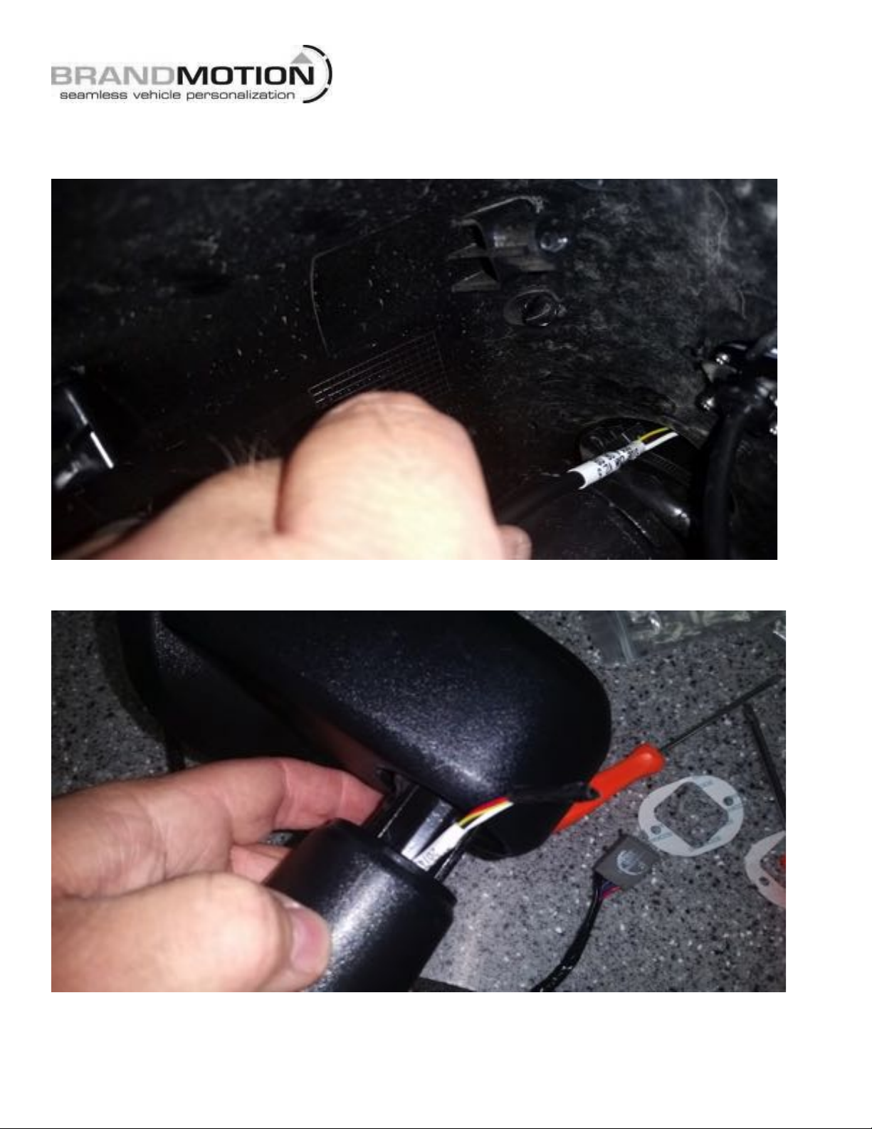
16. Tape the terminals to a zip tie to help guide the wire through the back of the mirror and mounting arm.
Run the camera harness though the back of the mirror where the factory power harness passes through
and out the bottom of the mirror arm.
! INSTALLATION!INSTRUCTIONS!
AVMS-3701 Instructions 7-22-16 Page 17 of 28
17. Following the factory harness run the camera harness though the mounting base and pull the rest of the
camera harness through.
18. Attach the camera harness and the factory mirror harness to the pull wire that was already run through
the door and pull the harnesses to the inside of the vehicle.

! INSTALLATION!INSTRUCTIONS!
AVMS-3701 Instructions 7-22-16 Page 18 of 28
19. Notch the grommet to allow room for the camera harness.
20. Remount the mirror to the vehicle with the (2) Torx bolts.
21. Insert the camera pins into the connector for the camera.
22. Reconnect the mirror harness in the door.

! INSTALLATION!INSTRUCTIONS!
AVMS-3701 Instructions 7-22-16 Page 19 of 28
23. Run the camera harness along the factory harness in the door.
24. Run the camera wire through the factory door sleeve. Use a long zip tie or a fish tape.
! INSTALLATION!INSTRUCTIONS!
AVMS-3701 Instructions 7-22-16 Page 20 of 28
25. Run the camera wire to behind glove box area to connect to the 360º main control module. (Passenger
side camera harness may have excess length, coil excess and zip tie behind passenger kick panel.)
26. Reinstall door panel and mirror glass. (Press the mirror glass from the center and be careful not to break
the glass.)
27. Repeat for other side.
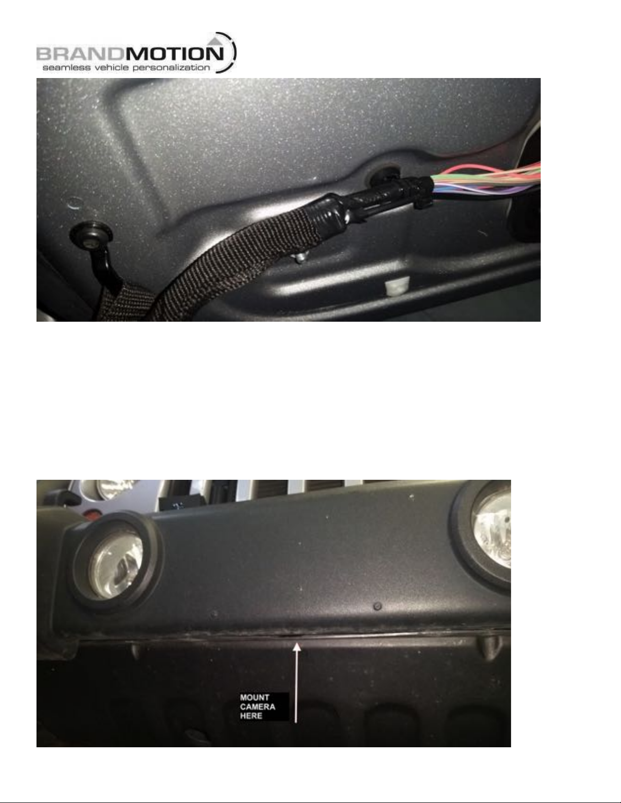
FRONT CAMERA INSTALL
1. Front camera will mount under the front bumper on the metal bumper.
Popular Machine Vision System manuals by other brands

Lumens
Lumens LC200 user manual

Vision & Control
Vision & Control TO88/21.5-140-V-B Instructions for use

National Instruments
National Instruments NI Vision CVS-1450 Series Getting started

Omron
Omron Vision Sensor FH Series Connection guide

CIS
CIS VCC-HD3 Product specification & operational manual

Baumer
Baumer VEXG-52 quick start guide


