BRANDRUP ISO-TOP MK VI User manual
Das ISO-TOP MK VI ist speziell für das Aluminium-
Aufstellda h der VW T6.1 / T6 California mit elektrohy-
draulis hem Aufstellda h und groß r Frontöffnung
entwi kelt und passt nur bei diesen. Vor der Erstbefe-
stigung muss die Grundhalterung am Fahrzeug ange-
bra ht werden.
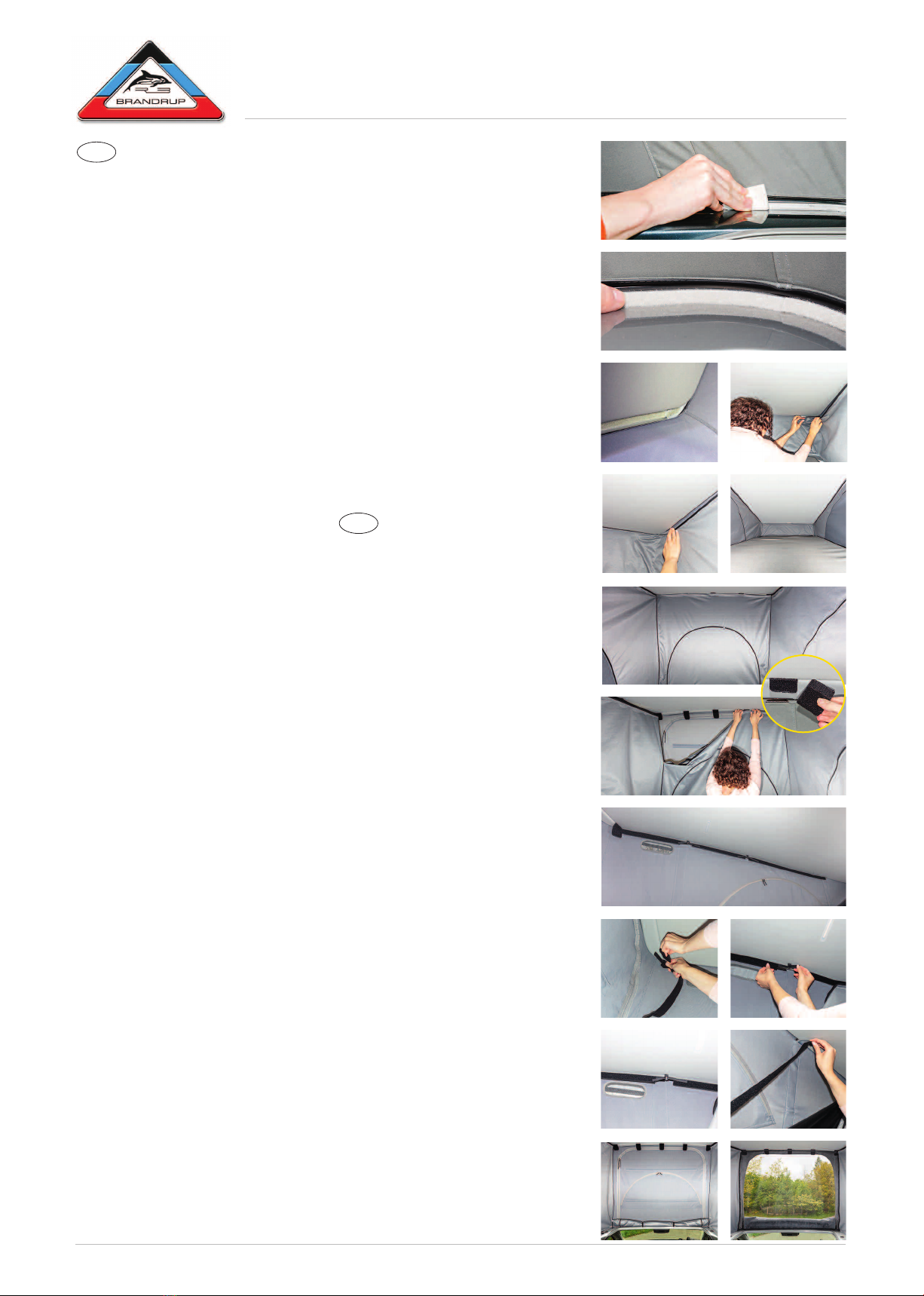
1. R inigung und Vorb r itung d r Montag st ll n
Die innere Aluminium-Basisumrandung (Rahmen) des
Faltenbalges ist mit dem beiliegenden Reinigungstu h
gründli h zu reinigen (vgl. Abb. 1). Ebenfalls ist hinten,
oben der la kierte Aluminiumda h-Streifen (glei h im
Ans hluss an den Textilverkleidungsteil) zu reinigen.
Dana h mindestens a. 15 Minuten ablüften lassen
und die glei hen Stellen mit dem beiliegenden Primer-
tu h vorbehandeln. Dana h no hmals a. 15 Minuten
ablüften lassen! Bitte verwenden Sie hierbei Hand-
s huhe und a hten Sie auf genügend Fris hluftzufuhr!
All Kl b arb it n dürf n nur b i in r Umg bungs-
t mp ratur üb r 18 Grad C lsius sowi g ring r
Luftf uchtigk it rfolg n!
2. Anbringung d r unt r n B f stigung
(s lbstkl b nd s Flauschband, Br it ca. 1 cm)
Das beiliegende, selbstklebende Flaus hband wird
rundherum auf den unteren Aluminium-Rahmen des
Faltenbalges so angebra ht, dass es si h knapp un-
terhalb des Faltenbalgeinzuges befindet (vgl. Abb. 2).
Das Flaus hband darf hierbei nur auf Metall aufgeklebt
werden und ni ht auf den Faltenbalgstoff!
Das Flaus hband muss mögli hst fest auf den Unter-
grund aufgedrü kt werden. In den E ken wird es ge-
teilt und Stoß an Stoß aufgeklebt, vgl. Abb. 2, gelber
Pfeil.
Nach d m Aufkl b n d s Flauschband s darf di s s
mind st ns 48 Stund n nicht b last t w rd n (ISO-
TOP no h ni ht befestigen) und dana h unbedingt
no hmals das Flaus hband gut auf den Untergrund
aufdrü ken.
3. Ob r H ckb f stigung
(s lbstkl b nd s Flauschband, Br it ca. 2 cm)
Ein passendes Stü k Flaus hband wird hinten oben
auf das la kierte Aluda h aufgeklebt und fest ange-
drü kt. Im E kberei h, ab der in Abb. 3 mit gelbem
Pfeil markierten Stelle, werden auf jede Seite je 4 runde
(Ø 2 m) Flaus hbänder angebra ht. In den E ken wird
das ISO-TOP-Material so unter die Da hverkleidung
ges hoben, dass es si h oben um die E ken der Ver-
kleidung legt, vgl. Abb. 4, 5, 6.
4. Anbringung d r ob r n B f stigung vorn
Fünf Klettvers hluss-Pads werden in den vorderen
Da hverkleidungs-Spalt mit dem Klettteil einges ho-
ben, das Flaus hteil bleibt draußen, vgl. Abb. 7. Hier-
bei muss das Pad mit dem Klettteil kräftig
einges hoben werden. Diese Pads verbleiben auf
Dauer im Spalt (können nur mit Gewalt und lei hter
Aufrauhung der Textilverkleidung entfernt werden).
Zuerst wird die mittlere Spezialhalterung eingesetzt,
wofür genau die Mitte ausgemessen werden muss.
Dana h werden, von dem mittleren Pad ausgehend,
jeweils re hts und links je zwei weitere Pads ange-
bra ht, vgl. Abb 9, 15. D r Abstand zwisch n d n
Pads b trägt 23,5 cm.
5. B f stigung d s ISO-TOP MK VI
5.1 Die Befestigung erfolgt unten rundum di ht mit
Klettvers hluss.
5.2 Ob n vorn erfolgt die Befestigung an den fünf
Pads, vgl. Abb. 8, 9 und oben Ziff. 4.
5.3 Ob n s itlich
Die Befestigung erfolgt mittels Klettvers hluss:
a) Ein Flaus hband-Streifen wird mit dem s hma-
leren Klettteil, das si h beidseitig an den Enden
des Flaus hband-Streifens befindet, am äußersten
Pad (vgl. Abb. 11) und an der serienmäßigen
Kinders hutznetz-Öse befestigt, vgl. Abb. 12, 13.
b) Der zweite Flaus hband-Streifen wird an der vor-
deren und hinteren Kinders hutznetz-Öse mit
dem s hmaleren Klettteil befestigt, sodass si h
der Flaus hband-Streifen zwis hen den beiden
Kinders hutznetz-Ösen befindet, vgl. Abb. 10, 12.
c) Die dritte Befestigung erfolgt an der Kinders hutz-
netz-Öse (vgl. Abb. 10, roter Pfeil) und im Stoff-
Hohlsaum der hinteren „Segellatte“: Die am
Flaus hband-Streifen angenähte Kunststoffplatte
wird von oben in den Hohlsaum geste kt und bis
zum Ans hlag einges hoben, vgl. Abb. 14.
Beim Einführen vorsi htig vorgehen und darauf a hten,
dass der Hohlsaum ni ht zu stark unter Spannung
gerät, damit si h keine Hohlsaum-Nahtenden lösen.
Ans hließend wird das ISO-TOP mittels Klettver-
s hluss an den Flaus hband-Streifen befestigt.
Die Frontöffnung des ISO-TOP kann heruntergerollt
und mittels Gummiband an je zwei Knöpfen befestigt
werden, vgl. Abb. 15.
ACHTUNG: Di ISO-TOP Frontöffnung muss b im
Schli ß n d s Aufst lldach s ntf rnt w rd n!
Vorn langsam die Luft entwei hen lassen (ni ht „stop-
fen“!) und vorsi htig das Fahrerhaus-Da hrollo s hlie-
ßen! Das Da h ist immer na h dem Absenken von
außen auf korrektes S hließen zu überprüfen. Falls es
ni ht ri htig, rundum völlig bündig s hließt: ISO-TOP
abnehmen.
ACHTUNG! Beim California Aufstellda h gilt stets
(ohne oder mit ISO-TOP): Beim S hließen des Da-
hes ist immer nur in d m Wind abg wandt s
(Leeseite) Fenster oder Tür geöffnet zu halten – die
luvseitigen sind zu s hließen!
Abb. 16: Die Frontöffnung des ISO-TOP MK VI kann
dur h ein FLYOUT Moskitonetz ersetzt werden
(Zubehör: Art.-Nr.: 100 701 069), das mittels Reißver-
s hluss eingezogen und oben an den Pads befestigt
wird. Beim S hließen des Aufstellda hes sollte das
FLYOUT abgenommen werden.
ISO-TOP MK VI is spe ially designed for the ele tro-
hydrauli operated pop-up roof of the VW T6.1 / T6
California with front op ning and therefore only fits
into those vehi les. Before the initial fastening, the
basi fixation has to be atta hed to the vehi le.
1. Cl aning and pr paration of th installation ar as
The interior aluminum basi frame of the gaiter has to
be leaned thoroughly with the en losed leaning tis-
sue ( p. image 1). The varnished aluminum stripe at
the ba k at the top (adja ent to the textile lining) has
to be leaned, too. After that, air at least for approx.
15 minutes and then pretreat the same areas with the
en losed primer tissue.
After that, air the roof again for approx. 15 minutes!
While preparing the surfa es, please use gloves and
look out for suffi ient air supply!
Th glu ing proc ss has to b don at an ambi nt
air t mp ratur abov 18 d gr s C lsius (64, 4°F)
and low humidity.
2. Attaching th low r fixation
(s lf-adh siv fri z band, width approx. 1 cm)
Atta h the en losed self-adhesive frieze band all
around the lower aluminum frame of the gaiter, in a
way that it is pla ed right underneath the entran e of
the gaiter ( p. image 2). Hereby, glue the frieze band
only to the metal and not to the fabri of the gaiter!
Press the frieze band onto the surfa e as firmly as pos-
sible. In the orners it needs to be ut and atta hed
end-to-end, p. image 2, yellow arrow.
Aft r glu ing th fri z band, no pr assur may b
appli d to it for at l ast 48 hours (do not yet atta h
ISO-TOP). Thereafter, press the frieze band firmly onto
the surfa e again.
3. Attaching th upp r fixation at th back
(s lf-adh siv fri z band, width approx. 2 cm)
Glue a fitting pie e of frieze band onto the upper ba k
end of the varnished aluminium roof and firmly press
it down. In the orner region, as from the point on
whi h is marked with a yellow arrow in image 3, 4
round (Ø 2 m) frieze band pie es are atta hed on
ea h side. Dire tly in the orner the ISO-TOP material
is pulled under the roof lining, so that it fits around the
edges of the lining, p. image 4, 5, 6.
4. Attaching th upp r fixation at th front
Five hook-and-loop fastener pads are inserted into the
gap of the roof lining with the hook part, the loop part
remains outside, p. image 7. The pads remain in the
gap permanently (and an only be removed with for e
and minor damage to the interior lining). At first, insert
the middle spe ial support. Therefore measure out the
middle position of the front gaiter. Then, judging by the
pad in the middle, atta h two pads to its left and right
side, p. image 9, 15. Th distanc b tw n th pads
is 23,5 cm.
®
ISO-TOP MK VI
VW T6.1 / T6 California
씊씋
씈씉
➡
쐈쐉
➡
➡
➡
DE
EN
© 2019 by
BRANDRUP
Art.-Nr.: 900 701 068 28.09.2019 https://www.brandrup.d
➡
➡
➡
쐅

Änderungen und Irrtum vorbehalten. Errors and omissions ex epted. Sous réserve de hangements et d‘erreurs. Nos reservamos ante ambios y errores.
4. Pos d la fixation avant n haut
Rentrer inq re tangles de fixation auto-agrippante
ôté ro hets dans l’intersti e du revêtement du toit à
l’avant, la partie velours reste à l’extérieur, f. ill. 7. Pour
e faire, il faut introduire le re tangle à ro hets en for-
çant. Ces re tangles demeurent pour toujours dans
l’intersti e, (il faut for er pour les enlever, en éraillant
légèrement le revêtement).
Poser en premier lieu le support spé ial de fixation du
milieu : mesurer ave pré ision le milieu. Puis, en par-
tant du re tangle entral, poser respe tivement à
droite et à gau he de part et d’autre les deux autres
re tangles ( f. ill. 9, 15). La distanc ntr l s r ctan-
gl s st d 23,5 cm.
5. Installation d l’isolation ISO-TOP MK VI
5.1 En bas, la fixation se réalise de façon hermétique
en aplatissant l’isolation sur le pourtour grâ e aux
bandes à ro hets ousues sur l’extérieur.
5.2 En haut à l’avant, aplatir l’isolation sur les inq
re tangles, f. illustr. 8, 9 et le hiffre 4 plus haut.
5.3 En haut sur l s côtés : La fixation se réalise ave
des bandes auto-agrippantes.
a) Trois bandes velours permettent la fixation supé-
rieure. Une bande velours munie d’un mor eau de
bande ro hets plus étroite ousu à ha une de
ses extrémités s’a ro he sur le re tangle auto-
agrippant le plus à l’extérieur ( f. illustr. 11) et
passe dans les anneaux du filet de prote tion en-
fants d’origine ( f. illustr. 12, 13).
b)La deuxième bande velours, (toujours munie d’un
mor eau de bande ro hets plus étroite ousu à
ha une de ses extrémités,) s’a ro he dans la
bou le avant et dans la bou le arrière du filet de
prote tion enfants de telle sorte que la bande
velours se trouve entre les deux bou les du filet
de prote tion enfants ( f. illustr. 10, 12).
c) La troisième bande se fixe dans la bou le du filet
de prote tion enfants ( f. illustr. 10, flè he rouge)
et dans le trou-trou de tissu de la « baleine » arr-
ière : la languette de plastique ousue au ruban
velours est introduite par le haut dans le passant
de la « baleine » et poussée jusqu’à la butée
(f. illustr. 14). Pro éder en dou eur à l’enfilage en
faisant attention à e que le faux-ourlet ne soit pas
trop fortement tendu afin de ne pas dé oudre ses
outures aux extrémités.
Ensuite, la bande ro hets d’ISO-TOP se plaque
sur la bande velours.
Il est possible d’enrouler le panneau de l’ouverture
frontale vers le bas et de le maintenir ave un élastique
qui s’a ro he à deux boutons, f. illustr. 15.
ATTENTION : la f nêtr frontal d’ISO-TOP doit êtr
nl vé avant la f rm tur du toit r l vabl !
Devant, laisser l’air s’é happer dou ement (éviter le «
bourrage ») et fermer ave pré aution le volet roulant
de la abine ondu teur ! Après avoir redes endu le
toit, toujours ontrôler impérativement de l’extérieur
que la fermeture est orre te. Si le toit n’est pas fermé
orre tement, entièrement plaqué sur tout son pour-
tour, enlever ISO-TOP.
ATTENTION ! toujours valable pour tous les toits rele-
vables des California (ave ou sans ISO-TOP) – pour
refermer le toit, impérativement tenir ouverte une fenê-
tre ou une porte opposé au v nt ( ôté sous le vent) –
fermer absolument elles qui sont du ôté du vent.
Illustration 16 : on peut rempla er le panneau d’ouver-
ture frontale d’ISO-TOP par une moustiquaire FLYOUT
(A essoires, Art. N°. 100 701 069) munie d’une fer-
meture à glissière, et que l’on fixe en haut sur les re -
tangles. Il faut retirer FLYOUT pour refermer le toit
relevable.
ISO-TOP MK VI fue desarrollado espe ialmente para
el te ho abatible ele trohidráuli o de los VW T6.1 / T6
California con ap rtura frontal grand y fun iona so-
lamente on estos modelos. Antes del montaje ini ial
hay que instalar el soporte bási o en el vehí ulo.
1. Limpi za y pr paración d los ár as d montaj .
Se limpia el reborde de aluminio (mar o) del fuelle on
el trapo de limpieza adjunto ( p. imagen 1). También
hay que limpiar la tira de aluminio barnizada de la parte
trasera superior (que sigue al revestimiento de textil).
Después hay que airearlo por lo menos 15 minutos y
tratar las mismas áreas on el pañuelo „Primer“ ad-
junto. Después déjelo airear otra vez durante 15 minu-
tos. Por favor, utili e guantes y asegúrese de dejar
entrar sufi iente aire fres o.
¡Todos los trabajos d p gar s d b n d r alizar
con t mp raturas sup rior s a 18 grados C lsius y
poca hum dad d l air !
5. Attaching th ISO-TOP MK VI
5.1 The ISO-TOP is atta hed below losely all around
with hook-and-loop fastener.
5.2 Abov , at th front, it is atta hed to the five pads,
p. images 8, 9 and fig. 4.
5.3 Abov , at th sid s
Fixation with hook-and-loop fastener:
a) One looptape is atta hed to the farthest pad ( p.
image 11) and the eyes of the hild-safety net
with its smaller hook part, p. images 12, 13.
b) The se ond looptape is atta hed between the
two eyes of the serial hild-safety net with its
hook part, p. images 10, 12.
c) The third looptape is atta hed to the eyes of the
serial hild-safety net ( p. image 10, red arrow)
and the fabri hemstit h of the rear batten: The
plasti part, whi h is sewn onto the ISO-TOP, is
inserted from the top into the hemstit h and
pushed down into it, p. image 14. Be areful while
inserting it and make sure that the hemstit h is not
put under tension to avoid the loosening of the rear
seams of the hemstit h.
Thereafter the ISO-TOP is atta hed on the loop-
tapes with hook-and-loop fastener.
The front opening an be rolled down and atta hed
with straps to two buttons, p. image 15.
ATTENTION: Wh n closing th pop-up roof, th front
op ning of th ISO-TOP has to b r mov d!
Let the air es ape steadily (don’t stuff the textile into
the roof!) and autiously lose the roller blind at the top
of the abin! Always he k from the outside whether
the roof losed properly after lowering it. In ase it
does not lose properly, please remove the ISO-TOP.
ATTENTION! California pop-up roof (with or without
ISO-TOP): while losing the roof, only a window or
door which is opposit to th wind dir ction (lee) has
to be kept open - all windward ones have to be lo-
sed!
Imag 16: The front opening of the ISO-TOP an be
repla ed by a FLYOUT mosquito net (optional: ref. 100
701 069), whi h is atta hed with a zip and fastened to
the pads at the top of the front. FLYOUT should be re-
moved, when losing the pop-up roof.
L’isolation ISO-TOP-MK VI a été onçue spé ialement
pour le toit relevable éle trohydraulique en aluminium-
des T6.1 / T6 Volkswagen California av c grand ou-
v rtur frontal et ne s’adapte qu’à eux. Avant la
première installation, il faut mettre en pla e le support
de fixation de base sur le véhi ule.
1. Dégraissag t préparation d s mplac m nts
d montag
Dégraisser à fond la bordure de base intérieure en alu-
minium (le adre) du soufflet de toile ave la lingette
jointe. De la même façon, nettoyer en haut à l’arrière
la bande peinte du toit en aluminium (juste au ra or-
dement ave le revêtement textile). Ensuite, aérer au
moins un quart d’heure et prétraiter les mêmes empla-
ements ave la lingette jointe imprégnée de ou he
d’apprêt. Puis aérer en ore environ un quart d’heure !
Porter impérativement des gants pour e faire et veiller
à une arrivée suffisante d’air frais !
Réalis r impérativ m nt tous l s travaux d collag
à un t mpératur ambiant supéri ur à 18° ainsi
qu’à faibl humidité d l’air.
2. Pos d la fixation sur l bas (band v lours
auto-agrippant autocollant d‘ nv. 1 cm d larg )
Coller la bande velours fournie sur le pourtour inférieur
du adre en aluminium du soufflet, de façon à e
qu’elle soit à ras du soufflet ( f. Illustration 2), unique-
ment sur le métal, et non sur le tissu du soufflet ! Ap-
pliquer la pression la plus forte possible sur la bande
velours auto ollante pour qu’elle adhère au support.
Couper dans les angles et oller bord à bord, f. Illu-
stration 2, flè he jaune. Après l collag d la band
v lours, il st impératif d n ri n accroch r d ssus
p ndant au moins 48 h ur s ( .à.d. de ne pas en ore
installer l’ISO-TOP) et ensuite, il faut impérativement
presser en ore une fois très fort la bande velours sur
le support.
3. Pos d la fixation arrièr n haut (band v lours
autocollant d’ nv. 2 cm d larg )
Coller un mor eau de bande velours (d’env. 2 m de
large) oupé à la dimension de la largeur du toit en haut
à l’arrière sur la partie peinte du toit en alu en exerçant
une forte pression. Au niveau des angles, à partir de
l’empla ement marqué d’une flè he jaune dans l’illu-
stration 3, fixer de haque ôté quatre pastilles de
bande velours (Ø 2 m). Dans les angles, glisser ISO-
TOP sous le revêtement du iel du toit de telle sorte
qu’il épouse dans le haut les angles du revêtement, f.
illustrations 4, 5, 6.
FR
ES
2. Fijación d l soport inf rior (tira d floj l
autoadh siva, anchura aproximada 1 cm)
Ajuste la tira de flojel autoadhesiva (in luida) alrededor
del mar o de aluminio interior de tal manera que esté
un po o por debajo de la entrada del fuelle ( p. imagen
2). ¡Tenga uidado que la tira de flojel se pegue sola-
mente por en ima del metal y no en el tejido! Apriete
la tira de flojel firmemente al fondo. En las esquinas
separe la tira y péguela de tal manera que los bordes
oin idan, p. imagen 2, fle ha amarilla. Tras la fija-
ción d la tira d floj l, no la cargu durant 48 horas
(no fije aún el ISO-TOP) y después es indispensable
apretar la tira de flojel otra vez bien en al fondo.
3. Fijación d l soport sup rior tras ro (tira d floj l
autoadh siva, anchura aproximada 2 cm)
Una pieza de tira de flojel ajustada se apli a en la parte
superior trasera al te ho barnizado y se aprieta fuerte.
En la zona de la esquina, desde el punto señalado on
fle ha amarilla en la imagen 3, se apli an en ada lado
4 tiras redondas de flojel (ø 2 m). En las esquinas se
empuja el material ISO-TOP de tal manera por debajo
del revestimiento del te ho, que se pliega arriba alre-
dedor de las esquinas del revestimiento, p. imágenes
4, 5, 6.
4. Fijación d l soport sup rior d lant ro
Se introdu en 5 pads de suje ión autoadhesiva en la
rendija delantera del revestimiento on la tira de gan-
hos, la tira de flojel queda fuera, p. imagen 7. Hay
que introdu ir el pad on la tira de gan hos on fuerza.
Estos pads se quedan permanentemente en la rendija
(se pueden quitar solamente on fuerza, ausando un
desperfe to leve en el revestimiento). Primero, se in-
trodu e el soporte espe ial del medio para lo ual hay
que medir exa tamente por donde queda el medio.
Después se pone dos pads más en ada lado, dos a
la dere ha y dos a la izquierda, teniendo omo refe-
ren ia el pad del medio, p. imagen 9, 15. La distancia
ntr los pads s 23,5 cm.
5. Fijación d l ISO-TOP MK VI
5.1 La fija ión se realiza abajo de forma herméti a on
inta de gan ho de suje ión.
5.2 Arriba, n la part d lant ra se fija en los 5
pads, ompare imágenes 8, 9 y arriba ifra 4.
5.3 Arriba d lado
La fija ión se realiza on inta de gan ho de
suje ión:
a) Una inta de tira de flojel se fija on la parte estre-
ha de la inta de gan ho que se en uentra en
ambos lados en los fines de la intas de tira de
flojel, en el pad exterior ( p. imagen 11) y en los
ojetes de la red de seguridad para niños, p.
imágenes 12,13.
b) La segunda inta de tira de flojel se fija en el ojete
de la red de seguridad para niños delantero y
trasero on la parte estre ha de la inta de gan-
ho, de tal manera que la inta de tira de flojel
queda entre ambos ojetes de la red de seguridad
para niños, p. imágenes 10, 12.
) La ter era fija ión se realiza en el ojete de la red
de seguridad para niños ( p. imagen 10, fle ha roja)
y en el dobladillo de tela del „listón“ trasero:
La tablilla de plásti o que está suturado, se intro-
du e desde arriba en el dobladillo hasta el fondo,
p. imagen 14. Al introdu ir la tablilla de plásti o
hay que tener uidado para que el dobladillo no
quede demasiado en tensión. Las osturas del
dobladillo podrían desha erse. Después se fija el
ISO-TOP a través de la ita de gan ho en las tiras
de flojel.
La ventana delantera del ISO-TOP se puede rollar
ha ía abajo y fijar en dos botones a través de una inta
de goma, p. imagen 15.
¡ATENCIÓN Ant s d c rrar l t cho abatibl , s d -
b ría quitar “La v ntana proa“ d l ISO-TOP d b d
star abi rta!
Deje salir el aire lentamente por la parte delantera (sin
“hen hir”), errando la persiana de la abina del on-
du tor on uidado. Siempre debe ontrolar desde
fuera si el te ho esté errado orre tamente. Si no
queda bien errado del todo, enton es quiete el ISO-
TOP. ¡ATENCIÓN! Con el te ho abatible de todos los
California hay que tener en uenta siempre (sin o on
ISO-TOP): al errar el te ho, se debe abrir solamente
una ventana o puerta que esté apartada del viento (so-
tavento) – las de barlovento hay que errarlas!
Imag n 16: La apertura delantera del ISO-TOP MK VI
se puede sustituir por una mosquetera FLYOUT (a e-
sorio: nro. de arti ulo 100 701 069), la ual se puede
introdu ir a través de una remallera y se fija en la
parte superior en los pads. Al errar el te ho abatible
el FLYOUT se debería quitar.
This manual suits for next models
1
Other BRANDRUP Tent manuals

Popular Tent manuals by other brands

Dancover
Dancover TentZing CT168200 manual

Coleman
Coleman 2000010387 Setup instructions

GigaTent
GigaTent Speed Devil owner's manual

AIRFRAMES ALASKA
AIRFRAMES ALASKA ARCTIC OVEN GREAT NUNATAK manual

Gorilla
Gorilla 3x3 Grow Tent instructions

Alice's Garden
Alice's Garden LUTECIA PT4X8KDWH Assembly instructions


