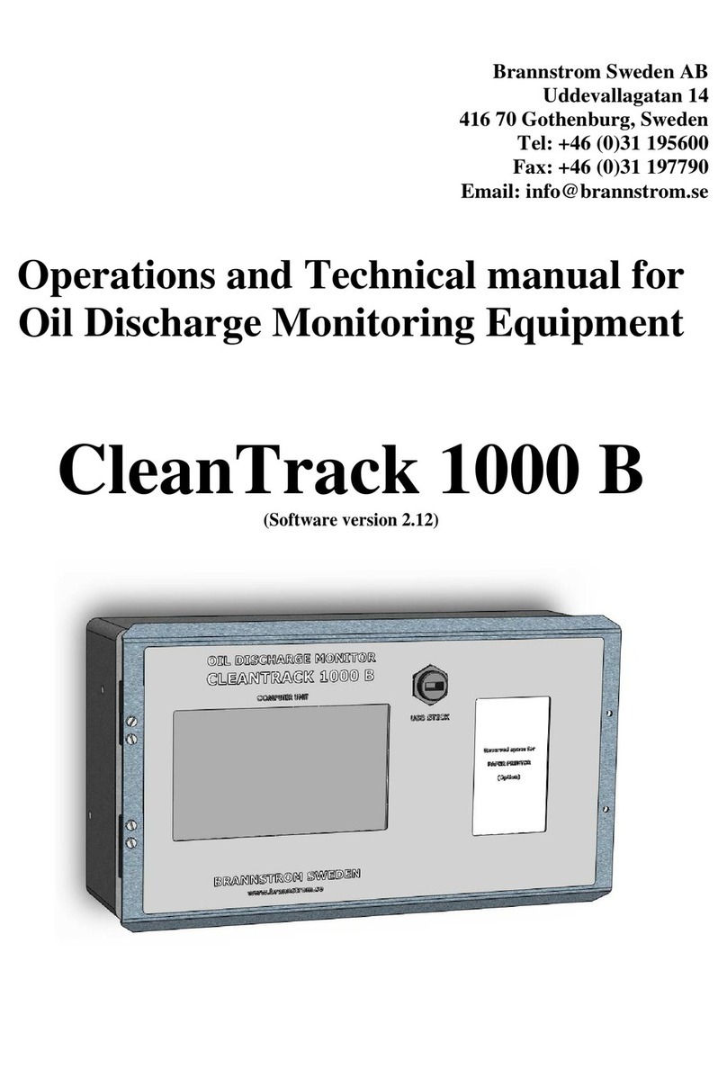
BRANNSTROM CleanTrack 1000 B User manual

Brannstrom Sweden AB
Uddevallagatan 14
416 70 Gothenburg, Sweden
Tel: +46 (0)31 195600
Fax: +46 (0)31 197790
Email: info@brannstrom.se
Operations and Technical manual for
Oil Discharge Monitoring Equipment
CleanTrack 1000 B
(Revision 2.20xd for Software version 2.20x)

Brannstrom Sweden AB CleanTrack 1000B - Rev 2.20xd, 2019 Page 2 of 232
Content
1. Introduction .......................................................................................................................................... 5
2. Important Notes ................................................................................................................................... 6
2.1. Component Replacement/Repair .......................................................................................................... 6
2.2. Disclaimer and Conditions ................................................................................................................... 6
2.3. Main news in software version 2.20x compared to version 2.12. ......................................................... 6
2.4. Updates in this manual. ........................................................................................................................ 7
3. Specification .......................................................................................................................................... 7
3.1. Description ........................................................................................................................................... 7
3.1.1. Function and main parts ..................................................................................................... 7
3.1.2. Measuring principle ........................................................................................................... 8
3.2. Scope of Supply and System Supplies .................................................................................................. 9
3.2.1. Parts always included in the Analyzing unit ...................................................................... 13
3.3. System Interfaces.................................................................................................................................. 14
4. Installation ............................................................................................................................................ 15
4.1. Computer Unit ...................................................................................................................................... 15
4.1.1. Mechanical ......................................................................................................................... 15
4.1.2. Electrical ............................................................................................................................ 15
4.2. Converting Unit .................................................................................................................................... 16
4.2.1. Mechanical ......................................................................................................................... 16
4.2.2. Electrical ............................................................................................................................ 16
4.3. Analyzing Unit ..................................................................................................................................... 17
4.3.1. General drawings ............................................................................................................... 17
4.3.2. Mechanical ......................................................................................................................... 17
4.3.3. Electrical ............................................................................................................................ 17
4.3.4. Inlet probe and Outlet stub ................................................................................................. 18
4.3.5. Piping of Sample Inlet and Outlet ...................................................................................... 19
4.3.6. Piping for Fresh water (Option) ......................................................................................... 19
4.3.7. Piping for Air motor (Air motor option only) .................................................................... 20
4.4. Flow meter and Speed log .................................................................................................................... 21
4.4.1. Flow meter general ............................................................................................................ 21
4.4.2. BRANNSTROM standard flow transmitter. ...................................................................... 21
4.4.3. Speed log general ............................................................................................................... 21
4.5. Paper Printer ......................................................................................................................................... 22
4.6. Response time calculations ................................................................................................................... 22
4.7. First Start up Checklist ......................................................................................................................... 23
4.8. Pressure alarm settings ......................................................................................................................... 24
4.9. Zener Barrier Instructions and Replacement ........................................................................................ 25
4.10. Measuring Cell Instructions and Replacement ................................................................................... 30
4.10.1. Measuring Cell replacement (CTB10032) ....................................................................... 33
4.11. Calculations on intrinsically safe arrangements .................................................................................. 36
5. Start/Stop procedure ............................................................................................................................ 38
5.1. General information before Start-up ..................................................................................................... 38
5.2. Start-up procedure ................................................................................................................................ 38
5.3. Close down procedure .......................................................................................................................... 39
5.4. Closing down for a longer time or preserving for sub-zero conditions ................................................. 39
6. Menu operations ................................................................................................................................... 41
6.1. Main Menu and Top of Page indications .............................................................................................. 41
6.2. Edit Numeric values ............................................................................................................................. 42
6.3. Keys ...................................................................................................................................................... 42
6.4. Password ............................................................................................................................................... 43
6.5. Measuring Cell - Indications and Keys ................................................................................................. 44
7. Menu layout .......................................................................................................................................... 45
7.1. Main Menu ........................................................................................................................................... 45
7.1.1. Start page ........................................................................................................................... 45
7.2. Operation .............................................................................................................................................. 46
7.2.1. Running ............................................................................................................................. 46
7.2.2. Running Settings ................................................................................................................ 47
7.2.2.1. "Discharge line" 47
7.2.2.2. "Oil type" 48
7.2.3. Manual Override ................................................................................................................ 51
7.2.4. Status ................................................................................................................................. 52
7.3. Alarm Table .......................................................................................................................................... 53
7.4. Recorded data ....................................................................................................................................... 54
7.4.1. Recorded data examples .................................................................................................... 55
7.5. USB ...................................................................................................................................................... 56
7.5.1. USB-Memory stick ............................................................................................................ 56
7.5.2. Save Printouts on USB stick .............................................................................................. 58
7.6. On-board Test ....................................................................................................................................... 59
7.7. Measuring Cell Check/Calibration ....................................................................................................... 63

Brannstrom Sweden AB CleanTrack 1000B - Rev 2.20xd, 2019 Page 3 of 232
7.7.1. Zero Calibration Status ...................................................................................................... 63
7.7.2. Zero Calibration Prepare .................................................................................................... 64
7.7.3. Zero Calibration Take Zero ............................................................................................... 65
7.7.4. Replace Measuring Cell ..................................................................................................... 66
7.8. Setup of parameters .............................................................................................................................. 67
7.8.1. Line of discharge ............................................................................................................... 67
7.8.2. ZF1 (Zener barrier flow input 1) ........................................................................................ 68
7.8.3. ZF2 .................................................................................................................................... 68
7.8.4. CVF ................................................................................................................................... 68
7.8.5. Pressure .............................................................................................................................. 69
7.8.5.1. Static Pressure/Water function 69
7.8.6. Motor (Optional Extended Converting unit I/O PCB) ...................................................... 70
7.8.7. Speed ................................................................................................................................. 70
7.8.8. System Configuration, Standard ........................................................................................ 71
7.8.9. System Configuration, Alarms&Extras ............................................................................. 71
7.9. Computer .............................................................................................................................................. 73
7.9.1. USB-Memory stick ............................................................................................................ 73
7.9.2. Real Time Clock ................................................................................................................ 73
7.9.3. IP-address .......................................................................................................................... 74
7.9.4. Touch Screen Calibration .................................................................................................. 74
7.10. System Check ..................................................................................................................................... 75
7.10.1. Main ................................................................................................................................. 75
7.10.2. Test .................................................................................................................................. 75
7.10.3. GPS (NMEA 0183 receiver) ............................................................................................ 76
7.10.4. Paper Printer _(Optional) ................................................................................................. 76
7.10.5. Expiry (Trial period) ...................................................................................................... 77
7.10.6. Power (Computer unit Power supply) ............................................................................ 77
7.10.7. CUIO (Computer unit I/O PCB) .................................................................................... 78
7.10.8. CVCT/Standard (Converting unit I/O PCB) .................................................................. 78
7.10.9. CVCT/Extended (Optional Extended Converting unit I/O PCB) ................................... 79
7.10.10. ZBCT (Converting unit Zener Barrier PCB) ................................................................ 79
7.10.11. MC (Measuring Cell) ................................................................................................... 80
7.10.12. External Modbus RTU (Optional CUIO) ..................................................................... 80
7.11. Approvals ........................................................................................................................................... 81
8. Fault-finding ......................................................................................................................................... 82
8.1. Malfunction of Computer/Converting unit ........................................................................................... 82
8.2. List of displayed alarms ........................................................................................................................ 82
8.3. System file errors .................................................................................................................................. 83
8.4. System communications errors ............................................................................................................. 84
8.5. External sensor alarms .......................................................................................................................... 85
8.6. Measurement alarms ............................................................................................................................. 86
8.7. Measurement sample alarms ................................................................................................................. 86
8.8. Paper Printer alarms ............................................................................................................................. 87
8.9. Extended Converting unit Motor alarms (Optional) ............................................................................. 88
8.10. Miscellaneous Sample pump and Overboard Valve alarms. ............................................................... 88
8.11. Indications on PCB's ........................................................................................................................... 90
8.11.1. Computer unit I/O PCB indications ................................................................................. 90
8.11.2. Converting unit I/O PCB indications ............................................................................... 90
8.11.3. Extended Converting unit I/O PCB indications (Optional) .............................................. 91
8.11.4. Zener barrier PCB indications.......................................................................................... 91
9. Maintenance, Spare parts and Consumables ..................................................................................... 92
9.1. Software upgrading .............................................................................................................................. 92
9.2. Battery replacement .............................................................................................................................. 92
9.3. Saving Printouts and Settings on a USB memory stick ........................................................................ 92
9.4. Periodic Checks and Servicing ............................................................................................................. 92
9.5. Verification of accuracy and access to restricted parts ......................................................................... 93
9.6. Cleaning of Inlet Filter ......................................................................................................................... 93
9.7. Sample Pump Shaft seal oil refilling .................................................................................................... 93
9.8. Spare parts ............................................................................................................................................ 94
9.8.1. Computer Unit ................................................................................................................... 94
9.8.2. Converting Unit ................................................................................................................. 94
9.8.3. Analyzing Unit................................................................................................................... 94
9.8.4. Sample pump ..................................................................................................................... 94
9.8.4.1. Ex. motor Sample pump, SPP-100 94
9.8.4.2. Bulkhead mounted Sample pump, Nikuni 32MED22 94
9.8.4.3. Bulkhead mounted Sample pump, Matre P06 94
9.8.4.4. Air motor Sample pump, Speck Y2951 94
9.8.5. Fuses .................................................................................................................................. 94
9.9. Recommended Spare parts ................................................................................................................... 95
9.10. Consumables ...................................................................................................................................... 95
9.11. Storage before installation .................................................................................................................. 95
10. Figures and Drawings ........................................................................................................................ 96

Brannstrom Sweden AB CleanTrack 1000B - Rev 2.20xd, 2019 Page 4 of 232
10.1. Computer Unit .................................................................................................................................... 97
10.2. Converting Unit .................................................................................................................................. 100
10.3. Analyzing Unit ................................................................................................................................... 104
10.3.1. Analyzing Unit skid with Ex. motor Sample pump ......................................................... 104
10.3.2. Analyzing Unit with external Sample pump .................................................................... 107
10.3.3. Analyzing Unit with Freestanding items for External Sample pump ............................... 112
10.3.4. Analyzing Unit with Air motor Sample pump ................................................................. 114
10.4. SPP-100 Sample pump with Ex. Motor .............................................................................................. 119
10.5. Nikuni Sample pump for Bulkhead mounting .................................................................................... 121
10.6. Matre Sample pump for Bulkhead mounting ...................................................................................... 124
10.7. Connection box ................................................................................................................................... 126
10.8. Measuring Cell replacement ............................................................................................................... 128
10.9. GA-plans ............................................................................................................................................ 129
10.9.1. Partnames of typical arrangement .................................................................................... 129
10.9.2. GA-plan with Ex. motor Sample pump ............................................................................ 130
10.9.3. GA-plan with bulkhead penetrating Sample pump .......................................................... 133
10.9.4. GA-plan with Air motor Sample pump ............................................................................ 135
10.9.5. GA-plan with pilot controlled Air motor Sample pump................................................... 137
10.10. Electrical ........................................................................................................................................... 138
10.10.1. Electrical cable diagram for electrical Ex. motor sample pump ..................................... 138
10.10.2. Electrical cable diagram for bulkhead mounted sample pump ....................................... 139
10.10.3. Electrical cable diagram for air motor sample pump ..................................................... 140
10.10.4. Internal cable diagram for electrical sample pump motor .............................................. 141
10.10.5. Internal cable diagram for Extended SPP-100 sample pump motor (Optional) ............. 142
10.11. Sample probes .................................................................................................................................. 143
10.11.1. Sample probes installation arrangements 1” .................................................................. 143
10.12. Flow meter ........................................................................................................................................ 145
11. Approval Certificates ......................................................................................................................... 148
11.1. Certificate: MED-D ............................................................................................................................ 148
11.2. Type Approval, DNV ......................................................................................................................... 150
11.3. Type Approval, Germany ................................................................................................................... 154
11.4. IMO Certificate, CCS ......................................................................................................................... 158
11.5. Type Approval, CCS .......................................................................................................................... 160
11.6. Type Approval, NK ............................................................................................................................ 163
11.7. Type Approval, RMRS ....................................................................................................................... 164
12. ATEX Certificates and Instructions ................................................................................................. 166
12.1. Declaration of Conformity .................................................................................................................. 166
12.2. ATEX Certificate Zener Barrier PCB ................................................................................................. 169
12.3. ATEX Certificate Measuring Cell ...................................................................................................... 174
12.4. Pressure transmitter, Danfoss ............................................................................................................. 178
12.5. Pressure transmitter, Siemens ............................................................................................................. 185
12.5.1. Declaration of Conformity ............................................................................................... 185
12.5.2. ATEX Certificate ............................................................................................................. 187
12.6. Flow meter, Siemens .......................................................................................................................... 190
12.7. Flow meter, Fuji ................................................................................................................................. 198
12.8. Sample Pump, SPP-100 with Elprom explosion proof motor ............................................................. 201
12.8.1. Elprom instructions .......................................................................................................... 201
12.8.2. Elprom Certificate, EPT 17 ATEX 2588 X ..................................................................... 205
12.8.3. Elprom Certificate, EUM1 10 ATEX 0350 ..................................................................... 209
12.8.4. Hummel Cable Gland Certificate, DEKRA 12ATEX0139 X .......................................... 226
12.9. Sample Pump, Speck pump with Gast air motor ................................................................................ 228
13. Appendix, Work shop test and Calibration Certificate .................................................................. 229
14. Project specific drawings and data sheets ........................................................................................ 231

Brannstrom Sweden AB CleanTrack 1000B - Rev 2.20xd, 2019 Page 5 of 232
1. Introduction
The Oil Discharge Monitoring System, CleanTrack 1000 B, has been designed to provide means of
monitoring, recording and controlling the ballast discharge in accordance with the requirements in
Resolution MEPC.108(49) as amended by Resolution MEPC.240(65) and is also approved for Bio-
fuel blends in accordance with MEPC.1/Circ.761 as revised.
The requirements of the MARPOL Convention are that all oil tankers with a gross tonnage of 150
GRT and above must have an oil discharge monitoring and control system installed with an
automatic overboard valve control system.
The requirements in Resolution MEPC.108(49) as amended apply to tankers with a date of keel
laying or equivalent stage of construction of 1st of January 2005 or later. Tankers with a keel laid
before 1st of January 2005 should comply either with these new or the older Guidelines and
Specifications.
Discharge limits are set at 30 liters per nautical mile (fixed) and a total discharge limit in liters (to
be set by the user) equaling 1/30,000 part of the particular cargo of which the residue formed a part.
The unit has also a 15 ppm mode intended for clean ballast.
The recording device is formatted electronically as mentioned in MEPC.108(49) chapter 6.9.1.
Recorded data is stored in a non-volatile memory and can hold approximately 3,000,000 printouts.
Optionally a paper printer can also be installed in the computer unit.
In addition to this equipment manual, the ship builder, installation contractor or whoever is
commissioned by the ship owner to do it, will prepare ship specific documentation in the form of a
manual covering the parts not covered by this equipment manual. For details see MEPC.108(49)
sections 9.3 – 9.8 and 11.1.4 – 11.1.6.

Brannstrom Sweden AB CleanTrack 1000B - Rev 2.20xd, 2019 Page 6 of 232
2. Important Notes
2.1. Component Replacement/Repair
Placement of security seals on critical components is to prevent tampering by unauthorized
personnel. Replacement or repair of this equipment should only be carried out under guidance of
Brannstrom Sweden AB.
2.2. Disclaimer and Conditions
All information provided by Brannstrom Sweden AB about this equipment is given in good faith
and is based on the best knowledge available at the particular time. No responsibility is, however,
assumed for possible inaccuracies or omissions.
The content of this manual may be copied as required for operational use on the vessel in which the
equipment is installed. This Manual must not be copied, in full or in part, for disclosure to third
part.
The software incorporated in the equipment is furnished on a strictly “as is” basis. The software is
proprietary to Brannstrom Sweden AB. The disclosure of the software coding is not allowed. The
software may not be copied in whole or part.
2.3. Main news in software version 2.20x compared to version 2.12.
1. It can be upgraded to handle 5 more bio-fuel blends to a total of 10 bio-fuel blends.
2. It listens to more GPS NMEA 0183 sentences, in addition to RMC also GLL, GGA and VTG.
3. It supports version 4.10 of GPS NMEA 0183 sentences.
4. Manual “Oil concentration” selection disables start of the sample pump and ignores readings from the
Measuring cell.
5. It can monitor feedback from the sample pump start/stop contactor.
6. It can monitor feedback from a sample pump motor disconnector switch. Switch is not in scope of delivery.
7. It has an optional alarm for freezing risk of water in the Measuring cell.
8. It has programmable feedback timeout for two overboard valves.
9. If the converting unit is fitted with the optional sample pump motor heating to avoid moisture in “StandBy”
mode, it can control the heating and monitor the motor voltage, current, cos φ, frequency, and overheating.
Documentation for this feature is delivered with special orders only.
10. For specially built computer units with an optional Modbus RTU serial communication channel, it can
communicate with the cargo control system. Documentation for this feature is delivered with special orders
only.
11. For specially built computer units with an optional NMEA alike serial communication port it can send printout
data to a listener. Documentation for this feature is delivered with special orders only.
12. It has settings for optional control of the slop tank valve separately using the relay output normally intended to
control the overboard valve no. 2. Documentation for this feature is delivered with special orders only.
13. Automatically recorded data compressed from 9 lines to 6 lines (MEPC.108(49) Chapter 6.9.2).
14. Naming of oil types closer to naming in applicable IMO resolutions.
15. Flow alarms are no longer generated while flow is in manual mode (“Manual Flow” is activated).
2.203
16. For optional extended converting unit only: New setting “Extended-NoLim” in property
“ConvertingUnitType” with limited motor alarms.
2.204
17. For optional extended converting unit only: “Disable Motor check” disables motor windings ptc alarms also.
Voltage of an activated heater is shown on top screen indications, “StandBy” -> “StandBy, xxV”.

Brannstrom Sweden AB CleanTrack 1000B - Rev 2.20xd, 2019 Page 7 of 232
2.4. Updates in this manual.
A detail information about changes in this manual compared to the previous manual, version 2.12k, is not meaningful as
there are too many details, computer menus and certificates that are changed, removed or added. Instead the major
functional changes have been listed above.
Version 2.20x -> 2.20xc:
1. New “Declaration of Conformity”, issued 2019-01-02. Chapter 12.1. Declaration of Conformity page 166.
2. Upgrade of details changed in software version 2.204. Changes for optional extended converting unit only.
Version 2.20xc -> 2.20xd:
1. New “Declaration of Conformity”, issued 2019-01-02. Chapter 12.1. Declaration of Conformity page 166.
3. Specification
3.1. Description
Type CleanTrack 1000 B
Application Oil Discharge Monitoring and Control System for Oil Tankers in
accordance with MEPC.108(49) as amended by Resolution MEPC.240(65),
approved for Crude oils and Petroleum products as well as for 10 types of
Bio-fuel blends in accordance with MEPC.1/Circ.761 as revised.
Range 0 - 1000 ppm
Accuracy According to MEPC.108(49)
Sample Flow rate 240 liters/hour to 900 liters/hour depending on sample pump model.
Clean water connection (optional):
Flow rate Intermittently 200 to 600 liters/hour depending on sample pump model and
water pressure.
Clean water is only used at Discharge Start and Stop.
Approximately 6-20 liters per Start/Stop (when applicable).
Pressure max. 5 bar
min. 0.5 bar higher than the pressure in the overboard line at the sample
outlet connected point.
3.1.1. Function and main parts
Purpose and function of the CleanTrack 1000B.
On an oil tanker the CleanTrack 1000B monitors and controls the discharge of oily water from a slop tank to the sea
according to MARPOL Annex I regulation 34, and it is specified in detail in IMO resolution MEPC.108(49).
When water is pumped from the slop tank into the discharge pipe, it can be diverted either back to the slop tank via a
slop tank valve, or over board to the sea via an overboard valve.
Normally the overboard valve is closed and the slop tank valve is open, diverting the water back to the slop tank. The
water can be diverted to the sea only when the CleanTrack 1000B enables opening of the overboard valve.
The CleanTrack 1000B samples water from the discharge pipe and measures the oil content of it. The CleanTrack
1000B also receives info about the ship’s speed (from the ship’s speed log or the GPS), the water flow rate from a flow
meter in the discharge pipe, and the ship’s position (from the GPS). Based on this info, the CleanTrack 1000B
calculates the instantaneous discharge rate of pure oil per nautical mile, and the total quantity of pure oil discharged.
The instantaneous rate of discharge of oil content must not exceed 30 liters per nautical mile, and the total quantity of
oil discharged into the sea must not exceed 1/30000 of the total quantity of the particular cargo of which the residue
formed a part.
When start pumping water from the slop tank, the water is diverted back to the slop tank. When the CleanTrack
1000B has determined that none of the above discharge limits are exceeded, it enables diverting the water into the
sea. When any of the discharge limits are reached, or there is a failure of the CleanTrack 1000B or any of the external
signals are missing, the overboard valve is automatically closed and the slop tank valve is opened. These events and
the corresponding ship’s position are recorded by the CleanTrack 1000B.

Brannstrom Sweden AB CleanTrack 1000B - Rev 2.20xd, 2019 Page 8 of 232
The unit consists of 4 main parts:
A Computer unit intended to be installed in the cargo control room or in an equivalent nonhazardous area.
The computer unit controls and receives data from the other CleanTrack components. This information is
treated for computing and control purposes and is documented in the unit`s memory required by IMO. The
other parts of the system are controlled from the computer unit. It also receives positioning data from the
GPS. This computer unit contains the parts and functions defined by IMO resolution MEPC.108(49) as the
“Control section”, “Control unit”, “Discharge interlock” and “Overboard discharge control”.
A Converting unit intended to be installed in the engine room or other suitable nonhazardous area. The
converting unit receives and transmits electrical signals from the analyzing unit to the computer unit. It
contains electrical power supply and zener barriers for the analyzing unit, a 2 wire 4 – 20 mA input for the
pressure transmitter and two, 2 wire 4 – 20 mA inputs for flow meters. The sample pump and optional fresh
water flushing control is also controlled by the converting unit.
An Analyzing unit intended to be installed in the pump room or other hazardous cargo area. The analyzing
unit contains the measuring cell and the pressure transmitter that monitors the sample flow through the
measuring cell. The pressure transmitter measures the pressure on the outlet of the sample pump and is used
to protect the pump from blockages or starvation.
The distance between the sampling probes and the analyzing unit should be as short as possible. The
maximum distance depends on the sample pump and the pipe diameter.
This analyzing unit corresponds to the “Oil content meter” as defined by IMO resolution MEPC.108(49).
A Sample pump of impeller type, to be installed close to the analyzing unit and normally in the pump room.
The sample pump prepares and feeds the sample from the overboard line to the measuring cell.
The sample pump can be of 3 main types. Depending on type is can be mounted in the hazardous area or on
the bulkhead between the engine room and the pump room.
1) With an air driven motor for mounting in hazardous area zone 1.
2) With a flameproof Exd motor for mounting in hazardous area zone 1.
3) Bulkhead mounted type with the electrical motor in the non-hazardous area (E/R) and the pump
in the hazardous area (P/R) zone 0 or zone 1.
3.1.2. Measuring principle
The measuring principle of the CleanTrack 1000B is based on a combination of light transmitted and light
scattering in four different angles. The sample water stream is homogenized in the sample feed pump and is
passed through a quartz glass tube where it is exposed to a light beam. The light transmitted and scattered in
the selected angles is dependent on the type and amount of contaminates in the water stream. Signals from
non-oil contaminants can be compensated for due to their different light scattering characteristics.

Brannstrom Sweden AB CleanTrack 1000B - Rev 2.20xd, 2019 Page 9 of 232
3.2. Scope of Supply and System Supplies
The CleanTrack 1000B parts:
1. Computer unit, 1 pc.
2. Converting unit, 1 pc.
a. Standard - for all electric motor sample pumps.
b. Standard Air - for air motor sample pump.
c. Extended - optional and for SPP-100 sample pump only.
3. Analyzing unit, 1 pc.
a. Skid with sample pump having explosion proof electric motor.
b. For external sample pump.
1. Compact cabinet.
2. Freestanding items with measuring cell hood.
c. Built in sample pump having air motor.
4. Sample pump, 1pcs
a. Explosion proof electric motor, normally mounted on skid in pump room.
b. Electric motor mounted on bulkhead, engine room/pump room.
c. Air motor, normally mounted inside analyzing unit.
5. Flow meter(s) – (Normally yard supply, supplied on request).
6. Sample probe(s) including valves and inlet filter – (Normally yard supply, supplied on
request).
7. Overboard valve and Slop tank valve – (Normally yard supply, supplied on request).
8. Pneumatic control box for Overboard and Slop tank valves – (Normally yard supply,
supplied on request).
9. Miscellaneous.
1. Computer unit:
Voltage 85-265 VAC
Frequency 50/60 Hz
Consumption 30 W
Ingress Protection IP42
Ambient Temp. 5 - 50 °C
Weight ~7 kg
Dimensions approx. 370 x 210 mm

Brannstrom Sweden AB CleanTrack 1000B - Rev 2.20xd, 2019 Page 10 of 232
2. Converting unit:
2.a. Standard - for all Electric Motor Sample Pumps: (door not displayed)
Voltage 380 or 440 VAC 3-phase
±10%, transient ±20%
Frequency 50/60 Hz
Consumption 120 W (exclusive pump)
Ingress Protection IP54
Ambient Temp. 5 - 50 °C
Weight ~14 kg
Dimensions approx. 550 x 360 x 130 mm
Color RAL-7035
Motor protection relay Suitable for sample pump motor current.
Or;
2.b. Standard Air - for Air Motor Sample Pump: (door not displayed)
Voltage 110 or 220 VAC
±10%, transient ±20%
Frequency 50/60 Hz
Consumption 120 W
Ingress Protection IP54
Ambient Temp. 5 - 50 °C
Weight ~14 kg
Dimensions approx. 550 x 360 x 130 mm
Color RAL-7035
Or;
2.c. Extended - Optional for SPP-100 Sample Pump only: (door not displayed)
Voltage 380 or 440 VAC 3-phase
±10%, transient ±20%
Frequency 50/60 Hz
Consumption 120 W (exclusive pump)
Ingress Protection IP54
Ambient Temp. 5 - 50 °C
Weight ~14 kg
Dimensions approx. 550 x 360 x 130 mm
Color RAL-7035
Motor protection relay Suitable for SPP-100 sample pump motor current.
Please note, this is an optionally equipped converting unit and it can only be used together with the SPP-100 sample
pump. It has the capability of heating the sample pump motor with about 15 W and it can also monitor the voltage
between 2 phases, current of all 3 phases, the power factor and the resistance of the PTC resistors in the motor
windings. If unit is powered through a frequency converter measurement might be faulty.
For setting, see chapter 7.8.9. System Configuration, Alarms&Extras page 71.
See also drawing CTB10003 sheet 4 of 4, Converting Unit page 103.

Brannstrom Sweden AB CleanTrack 1000B - Rev 2.20xd, 2019 Page 11 of 232
3. Analyzing unit:
3.a. Skid with Sample Pump, Ex. proof Electric Motor:
(Voltage is supplied via converting unit)
Voltage 380 or 440 VAC 3-phase
Frequency 50/60 Hz
Power Consumption 0.66 kW
Sample flow 600 l/h (nominal)
Sample Temp. 0 - 65 ºC
Ambient Temp. -20 - +55 ºC
Weight ~35 kg
Dimensions approx. 350 x 410 x 250 mm
Color RAL-7035
See 4.a. below for more information about the Sample pump
Or:
3.b. For External Sample Pump: (door not displayed)
3.b.1. Compact Cabinet:
Sample flow 240-900 l/h (depending on sample pump)
Sample Temp. 0 - 65 ºC
Weight ~10 kg
Ingress Protection: IP56
Ambient Temp. -25 - +55 ºC1
Dimensions approx. 350 x 410 x 250 mm
Color RAL-7035
or:
3.b.2. Freestanding items with measuring cell hood:
(Intended for retrofit installation inside an existing cabinet)
(Existing sample pump and pressure transmitter to be used)
Sample flow 240-900 l/h (depending on sample pump)
Sample Temp. 0 – 65 ºC
Ingress Protection IP56
Ambient Temp. -25 - +55 ºC
Or:
3.c. With built in Sample Pump, Air Motor: (door not displayed)
Air pressure 5.2 bar
Air consumption ~30 Nm³/h
Sample flow 240 l/h (nominal)
Sample Temp. 0 - 65 ºC
Weight ~18 kg
Ingress Protection: IP56
Ambient Temp. +1 - +40 ºC1
Dimensions approx. 350 x 410 x 250 mm
Color RAL-7035
See 4.c. below for more information about the Sample pump
1 If sample temperature is higher than the ambient temperature limit the limit becomes lower or cabinet should be ventilated.

Brannstrom Sweden AB CleanTrack 1000B - Rev 2.20xd, 2019 Page 12 of 232
4.a. Sample pump SPP-100 with Explosion proof electric motor:
Supply voltage 400 VAC,50 Hz / 440 VAC,60 Hz 3-phase
Current 1.4 A / 1.5 A
Power Consumption 0.55 kW / 0.66 kW
Cos φ 0.78
Speed 2840 rpm / 3400 rpm
Sample flow 600 l/h (nominal)
Sample temp. 0 - +65 ºC
Ambient temp. -20 - +55 ºC
Ingress Protection IP66
Weight ~11.5 kg
Dimensions approx. 300 x 140 x 200 mm
Ex. class II 1 G Ex d IIC T4 Ga
Details See chapter 10.4. SPP-100 Sample pump with Ex. Motor page 119
and 12.8. Sample Pump, SPP-100 with Elprom explosion proof motor page 201.
4.b. Sample pump Nikuni 32MED22/Matre P06 for Bulkhead mounting:
Note that different motors might be used for these pumps over and technical data might differ slightly from
the ones given below. Please read the marking plate of the actual motor.
Supply voltage 380-420 VAC,50 Hz / 440-480 VAC,60 Hz 3-phase
Current 4.53 A / 4.74 A
Power Consumption 2.2 kW / 2.53 kW
Cos φ 0.86
Speed 2850 rpm / 3440 rpm
Sample flow 900 l/h (nominal)
Sample temp. 0 - +65 ºC
Ambient temp. 0 - +40 ºC
Ingress Protection IP55
Weight ~59 kg
Dimensions approx. 600 x 280 x 410 mm
Details Nikuni: See chapter 10.5. Nikuni Sample pump for Bulkhead mounting page 121.
Matre: See chapter 10.6. Matre Sample pump for Bulkhead mounting page 124.
4.c. Sample pump Speck Y-2951 with Air driven Gast motor:
Air pressure 5.2 bar
Air consumption ~30 Nm³/h
Sample flow 240 l/h (nominal)
Sample Temp. 0 - +65 ºC
Ambient Temp. +1 - +40 ºC2
Ingress Protection: IP56
Weight ~2.2 kg
Dimensions approx. 190 x 80 x 80 mm
Ex. class II 2 GDc T4
Details See chapter 12.9. Sample Pump, Speck pump with Gast air motor page 228.
2 If sample temperature is higher than the ambient temperature limit the limit becomes lower or cabinet should be ventilated.

Brannstrom Sweden AB CleanTrack 1000B - Rev 2.20xd, 2019 Page 13 of 232
3.2.1. Parts always included in the Analyzing unit
Measuring Cell (including its mounts):
Design Pressure 10 bar
Ingress Protection IP56
Ambient Temp. -25 - +55 ºC
Sample Temp. 0 - 65 ºC
Orifice on outlet Ø 2.5, 3.5 or 4.3 mm
(Speck Y-2951: Ø2.5 mm; SPP-100: Ø3.5 mm; Nikuni 32MED22/Matre P06 Ø4.3 mm)
Ex. class II 1 G Ex ia IIC T4 Ga Tamb -40ºC - +60 ºC
Connection Box, (for intrinsically safe circuits only):
Ingress Protection IP56
Ambient Temp. -25 - +55 ºC
Pressure transmitter:
Maker Siemens
Type 7MF1567–3CB01-1AA1
Ingress Protection IP65
Ambient Temp. -25 - +85 ºC
Sample Temp. 0 - +120 ºC
Measuring range 0-16 bar (4-20ma, 2-wire 24VDC loop powered)
Sample connection G½” mail thread
Length approx. 115 mm
Ex. Class II 1/2 GD Ex ia IIC T4 Ga/Gb
Alternative pressure transmitter:
Maker Danfoss
Type MBS 4251-2211-1AB08
Ingress Protection IP65
Ambient Temp. -40 - +100 ºC
Sample Temp. 0 - +125 ºC
Measuring range 0-16 bar (4-20ma, 2-wire 24VDC loop powered)
Sample connection G½” mail thread
Length approx. 135 mm
Ex. Class II 1 G Ex ia IIC T6…T4 Ga
General pressure transmitter requirements:
Type 4-20mA, (2-wire 24VDC loop powered)
Ingress Protection as for the particular application.
Ambient Temp. -25 - +55 ºC
Sample Temp. 0 - +65 ºC
Measuring range 0-16 bar (any range 0-10 bar to 0-25 bar can be used)
Sample connection G½” male thread
Ex. Class must comply with the particular hazardous area

Brannstrom Sweden AB CleanTrack 1000B - Rev 2.20xd, 2019 Page 14 of 232
3.3. System Interfaces
This section contains a list over electrical interfaces in the system with an electrical sample pump.
More details about these signals’ setup can be found in chapter 7.8. Setup of parameters page 67 and about
their connections in chapter 10.10. Electrical page 138.
Description
Type
Unit
Subunit
Terminal
Mains, Computer unit
85-265VAC, 50/60Hz,
1-phase
Computer
Power unit
1, 2
Mains, Converting unit
440VAC, 60Hz, 3 phase/
380VAC, 50Hz, 3 phase
Converting
Power terminals
41-43
Communication, internal
Modbus RTU, RS485
Computer/
Converting
internal
Comp. I/O
Conv. I/O
Zener Barrier
17-19
21-23
Communication, internal
Ex3, patented
Converting/
Analyzing/
internal
Analyzing
Zener Barrier/
Connection box/
Measuring cell
ZMC
1, 2/
Header
Socket
Communication, external
(optional)
Modbus RTU, RS485
Computer
Comp. I/O
44-46
Flow meter inputs
ZF1
ZF2
CVF
Ex4, 4-20mA, active,24VDC
Ex4, 4-20mA, active,24VDC
4-20mA, passive
Converting
Converting
Converting
Zener Barrier
Zener Barrier
Conv. I/O
ZF1
ZF2
CVF
Pressure transmitter input
(internal)
Ex5, 4-20mA, active,24VDC
Cable, preinstalled
Converting/
Analyzing/
Analyzing
Zener Barrier/
Connection box/
Pressure transm.
ZP
7, 8
2, 1
Overboard valve control
EL1
EL2
Relay, potential free
Relay, potential free
Computer
Computer
Power unit
Power unit
3, 4
5, 6
Manual override output
Relay, potential free
Computer
Power unit
7, 8, 9
Alarm output
Relay, potential free
Computer
Power unit
10,11,12
GPS receiver
NMEA 0183, 4800 baud
Computer
Comp. I/O
21-23
VDR transmitter (optional)
NMEA type, 4800 baud
Computer
Comp. I/O
41-43
Overboard valve position input
EL1
EL1-INV (open indicate open)
EL1-ZD1
EL2
EL2-INV (open indicate open)
EL2-ZD2
12 VDC, 10mA
12 VDC, 10mA
Ex6, 7 VDC, 10mA
12 VDC, 10mA
12 VDC, 10mA
Ex6,7 VDC, 10mA
Computer
Computer
Converting
Computer
Computer
Converting
Comp. I/O
Comp. I/O
Zener Barrier
Comp. I/O
Comp. I/O
Zener Barrier
26, 27
26, 27
ZD1
28, 29
28, 29
ZD2
Speed log input
12 VDC, 10mA
Computer
Comp. I/O
30, 31
El. Sample pump control
Contactor 440 VAC
Converting
Power terminals
44-46
Fresh water valve control
Relay, 24 VAC
Converting
Conv. I/O
3, 4
Sample select control
S1
S2
Relay, 24 VAC
Relay, 24 VAC
Converting
Converting
Conv. I/O
Conv. I/O
5, 6
7, 8
Sample pump motor dis-
connector switch feedback
12 VDC, 8mA
Converting
Conv. I/O
13, 14
Sample pump contactor feedback
12 VDC, 8mA
Converting
Conv. I/O
15, 16
High oil temp sample pump
12 VDC, 8mA
Converting
Conv. I/O
17, 18
Overcurrent input, internal
24 VAC
Converting
Conv. I/O
26, 27
Manual fresh water valve position
input
Ex6, 7 VDC, 10mA
Converting
Zener Barrier
ZD4
Unit and Subunit locations: item, cabinet
Computer unit, Power unit: d1, CTB10001p sheet 3, Computer Unit with open door page 98
Computer unit, Comp. I/O d5
Converting unit, Power Terminals d3, CTB10003 sheet 3 of 4, Converting Unit page 102
Converting unit, Conv. I/O d5
Converting unit, Zener Barrier d6
Analyzing unit, Connection box d1, CTB10015 sheet 3 of 3, Analyzing unit skid with electrical Ex. motor sample pump page 106
Analyzing unit, Measuring cell d2
Analyzing unit, Pressure transmitter d4
3Interface for intrinsically safe communication between the Zener barrier and the Measuring cell.
4Interface for intrinsically safe flow meter only.
5Interface for intrinsically safe pressure transmitter only.
6Interface for intrinsically safe potential free contact.

Brannstrom Sweden AB CleanTrack 1000B - Rev 2.20xd, 2019 Page 15 of 232
4. Installation
This chapter contains advice for the installation of CleanTrack 1000 B equipment on board tankers. The advice given in
this chapter is of general validity and should be supplemented with a detailed installation specification for the particular
ship. Additionally, all applicable regulations regarding the installation standard, issued by the relevant authorities and
classification society must be followed.
For instance, if CENELEC applies, compliance is required with EN 60079-14 and EN 60079-17.
4.1. Computer Unit
4.1.1. Mechanical
Refer to drawings/chapters:
•CTB10030 sheet 1, chapter 10.1. Computer Unit page 97. Both wall and panel mount options are shown.
•P3715090 sheet 1, Computer Unit panel mount instructions page 99.
The Computer Unit is installed in the cargo control room or an equivalent dry and non-hazardous area.
4.1.2. Electrical
Refer to one of the drawings below:
•CTB110204.1el, chapter 10.10.1. Electrical cable diagram for electrical Ex. motor sample pump page 138.
•CTB110204.1bh, chapter 10.10.2. Electrical cable diagram for bulkhead mounted sample pump page 139.
•CTB110204.1pn, chapter 10.10.3. Electrical cable diagram for air motor sample pump page 140.
Supply voltage should be single phase 110/220VAC, 50-60Hz.
(Computer unit work on voltages 85 - 265VAC).
Power consumption 30VA.
The power should be equipped with a main switch, or if specified, a detachable connector.
The fuse size should be 6A.
The alarm relay is normally open. An activated alarm is indicated with an open relay, which means that the alarm is
activated when the power supply fails.
Data communication between Computer Unit and Converting Unit, Cb5:
Type: RS485
Baudrate: 19200 baud.
Length: ≤1200 meters. (Might be shorter depending on cable used, see RS485 standards.)

Brannstrom Sweden AB CleanTrack 1000B - Rev 2.20xd, 2019 Page 16 of 232
4.2. Converting Unit
4.2.1. Mechanical
Refer to drawing:
•CTB10003 sheet 1, chapter 10.2. Converting Unit page 100.
The Converting Unit should be mounted vertically in a non-hazardous area, normally in the engine room, as close as
possible to the Analyzing Unit at the other side of the bulkhead. The unit should be provided with enough space to open
the cabinet door.
4.2.2. Electrical
Refer to drawings:
•CTB10003 sheet 2 of 4, Converting Unit page.101.
•CTB10003 sheet 3 of 4, Converting Unit page 102.
oItem d7 = equipotential rail, in the text below.
oItem d8 = PE rail, in the text below.
For electrical explosion proof motor sample pump:
•CTB10907 sheet 1 of 1, GA-plan with skid Ex. motor sample pump page 130.
•CTB10917 sheet 1 of 1, GA-plan with skid Ex. motor sample pump and flushing page 131.
•CTB10908 sheet 1of 1, GA plan with free standing Ex. Motor sample pump page 132.
•CTB110204.1el, electrical cable diagram for electrical Ex. motor sample pump page 138.
For electrical bulkhead penetration sample pump:
•CTB10906 sheet 1 of 1, GA-plan with bulkhead penetrating Sample pump page 133.
•CTB10916 sheet 1 of 1, GA-plan with bulkhead penetrating Sample pump and flushing page 134.
•CTB110204.1bh, electrical cable diagram for bulkhead mounted sample pump page 139.
For air motor sample pump:
•CTB10901 sheet 1 of 1, GA-plan with air motor sample pump page 135.
•CTB10911 sheet 1 of 1, GA-plan with air motor Sample pump and flushing page 136.
•CTB10903 sheet 1 of 1, GA-plan with pilot-controlled air motor sample pump page 137.
•CTB110204.1pn, electrical cable diagram for air motor sample pump page 140.
Refer also to the document “INSTRUCTIONS Oil Monitor interface type Z11”
•Chapter 4.9. Zener Barrier Instructions and Replacement page 25.
The power supply should be equipped with a main switch, or if specified, a detachable connector. Fuse size should be 3
x 10A for Converting Units equipped to supply electrical motor sample pumps and a 6A fuse for air motor sample
pumps. Check that the supply voltage corresponds to the voltage specified on the label below the mains terminals.
A 3-pole disconnector switch can be installed in the safe area on Cb2 to being able to detach the sample pump while
keeping power to the converting unit. This can be useful if a zener barrier input is used for the overboard valve
feedback. An additional normally closed auxiliary contact can be monitored by the unit.
Shields of cables for intrinsically safe equipment in both hazardous and non-hazardous area should normally be
electrically connected to earth at one point only, normally in the non-hazardous area end of the circuit loop. This
requirement is to avoid the possibility of the screen carrying a possibly incentive level of circulating current in the event
that there are local differences in earth potential between one end of the circuit and the other.
All shields of Cb7 and other cables for intrinsically safe equipment connected to the Zener Barrier PCB should
be connected to earth. This is made via the equipotential rail (see CT10003 sheet 3 page 102, item d7) located
below the Zener Barrier PCB at the right side in the Converting Unit. The rail is from factory connected to the
PE rail (see CT10003 sheet 3 page 102, item d8) located at the low left side in the Converting Unit. The PE rail
shall be connected to ground/earth (and the equipotential rail is then also connected to ground/earth).
If another earthing system is preferred for the cable shields of the intrinsically safe equipment the equipotential rail
should be disconnected from the PE rail and instead connected to the preferred earthing system.
Connections must satisfy the requirements of the relevant classification society.
Keep Cb7 and other cables connected to intrinsically safe circuits separated from non-intrinsically safe circuit cables.
Data communication between Converting Unit and Analyzing Unit, Cb7:
Baudrate: 19200 baud.
Length: ≤50 meters.

Brannstrom Sweden AB CleanTrack 1000B - Rev 2.20xd, 2019 Page 17 of 232
4.3. Analyzing Unit
4.3.1. General drawings
For item numbers and piping of a typical arrangement refer to drawing:
•CTB10601 sheet 1 of 1, Partnames of typical arrangement page 129.
The Analyzing Unit/Measuring Cell should be mounted vertically and lower than the sample outlet probe, to safeguard
a positive pressure in the sample water system at all times.
For draining possibilities of the sample piping arrangement, the drain valve, item 42, should be the lowest point.
A separate draining possibility for the pump head of the sample pump is needed for some pump types.
4.3.2. Mechanical
For skid mounted electrical Ex. motor sample pump refer to drawings/chapters:
•Chapter 10.3.1. Analyzing Unit skid with Ex. motor Sample pump page 104.
For free standing electrical Ex. motor sample pump refer to drawings/chapters:
•Chapter 10.4. SPP-100 Sample pump with Ex. Motor page 119.
For electrical bulkhead penetration sample pump refer to drawings/chapters:
•Chapter 10.3.2. Analyzing Unit with external Sample pump page 107.
•Chapter 10.5. Nikuni Sample pump for Bulkhead mounting page 121.
•Chapter 10.6. Matre Sample pump for Bulkhead mounting page 124.
For air motor sample pump refer to drawings/chapters:
•Chapter 10.3.4. Analyzing Unit with Air motor Sample pump page 114.
For retrofitting inside existing analyzing cabinet
•Chapter 10.3.3. Analyzing Unit with Freestanding items for External Sample pump page 112.
•Chapter 10.7. Connection box page 126.
The Analyzing Unit should be mounted in the pump room with 4 bolts welded clips on the pump room to engine room
bulkhead as close as possible to the Converting Unit at the other side of the bulkhead or in an equivalent suitable
location. The unit should be provided with enough space to open the cabinet door and enough space to facilitate
cleaning of the Measuring Cell from above with a brush. There should also be space for operating the valve handles and
taking grab samples.
The Analyzing Unit should be mounted lower than the sample outlet probe, to safeguard a positive pressure in the
sample water system at all times.
Any valves having coated aluminum levers should be protected from falling objects.
4.3.3. Electrical
For skid mounted/free standing electrical Ex. motor sample pump refer to drawings/chapters:
•Chapter 12.8.1. Elprom instructions page 201
•CTB110204.1el, electrical cable diagram for electrical Ex. motor sample pump page 138
•Chapter 10.3.1. Analyzing Unit skid with Ex. motor Sample pump page 104.
•Chapter 10.7. Connection box page 126
For electrical bulkhead penetration sample pump refer to drawings/chapters:
•CTB110204.1bh, electrical cable diagram for bulkhead mounted sample pump page 139.
•Chapter 10.3.2. Analyzing Unit with external Sample pump page 107
•Chapter 10.7. Connection box page 126
For air motor sample pump refer to drawings/chapters:
•CTB110204.1pn, electrical cable diagram for air motor sample pump page 140.
•CTB10010 sheet 3 of 5, Analyzing unit with air motor sample pump page 116.
•CTB10010 sheet 5 of 5, Analyzing unit with air motor sample pump page 118.
•Chapter 10.7. Connection box page 126

Brannstrom Sweden AB CleanTrack 1000B - Rev 2.20xd, 2019 Page 18 of 232
For retrofitting inside existing analyzing cabinet.
Mount a freestanding measuring cell mounted with its hood and a connection box on the backplane.
Refer to drawings/chapters:
•Use cable diagram above for the actual sample pump used.
•CTB10601 sheet 1 of 1, Partnames of typical arrangement page 129.
•10.3.3. Analyzing Unit with Freestanding items for External Sample pump page 112.
•Chapter 10.7. Connection box page 126
Refer also to the document “INSTRUCTIONS Measuring cell type CTB11”
•Chapter 4.10. Measuring Cell Instructions and Replacement page 30 that also contains the drawings
CTB10032, CTB10033 sheet 1 and CTB11036.
Check the Sample pump, the Measuring Cell and the Pressure transmitter documentation concerning intrinsically safety
and that the equipment complies with the installation regulations for this particular hazardous area.
Connect Cb7, Cb3 and Cb3a to the Connection box. Terminate the Cables according to the electrical cable diagram for
the actual sample pump used.
Shields of Cb7, Cb3 and Cb3a should all normally be connected to the equipotential rail in the Connection Box
of the Analyzing Unit. The equipotential rail and shields are normally connected to earth in the nonhazardous
area.
Cables Cb3 and Cb3a can also be directly wired from the flow meter to the Converting Unit without connections via the
Connection box.
Make sure the Analyzing Unit and the Connection box is properly connected to earth according to the applicable
regulations for this particular hazardous area.
If an electrical Ex Sample pump is used:
If a thinner cable, Cb2 is used than given in drawing CTB10015 sheet 2 of 3, Analyzing unit skid with electrical Ex.
motor sample pump page 105 size down with a cable gland approved for the actual hazardous area and the pump
temperature.
Make sure the frame of the explosion proof motor is properly connected to earth according to the applicable regulations
for this particular hazardous area. Refer to maker’s instruction chapter 12.8.1. Elprom instructions page 201 regarding
connection of power supply and earth.
4.3.4. Inlet probe and Outlet stub
For basic convention requirements, see Resolution MEPC.108(49) chapter 6.3.
Refer to drawings in chapter 10.11. Sample probes page 143.
The inlet probe is mounted upstream of the outlet stub and the flow meter sensor should preferably be mounted between
the inlet probe and the outlet stub. A positive water pressure must be available in the discharge line under all discharge
conditions at the place where the inlet probe is located. The outlet probe shall be located higher than the analyzing unit
outlet connection. The sample feed pump may be damaged if run dry for more than 10 seconds.
The sample valves and sample inlet filter should be located with adequate space and accessibility for servicing.

Brannstrom Sweden AB CleanTrack 1000B - Rev 2.20xd, 2019 Page 19 of 232
4.3.5. Piping of Sample Inlet and Outlet
Pipes: Tb11 and Tb13
For skid mounted/free standing electrical Ex. motor sample pump refer to drawings/chapters:
•Chapter 10.9.2. GA-plan with Ex. motor Sample pump page 130.
•Chapter 10.3.1. Analyzing Unit skid with Ex. motor Sample pump page 104.
Recommended pipe dimensions for SPP-100 pump:
Pipe diameter 15x1 mm
Recommended maximum pipe length 10 m
According to response time calculations, maximum pipe length of Tb13 is 30 m. When using a long Tb13 pipe
it is important to consider the pressure drop in Tb13, please see point 1.and 3. below in this chapter.
For electrical bulkhead penetration sample pump refer to drawings/chapters:
•Chapter 10.9.3. GA-plan with bulkhead penetrating Sample pump page 133.
•Chapter 10.3.2. Analyzing Unit with external Sample pump page 107.
•Chapter 10.5. Nikuni Sample pump for Bulkhead mounting page 121.
•Chapter 10.6. Matre Sample pump for Bulkhead mounting page 124.
Recommended pipe dimensions for Nikuni pump:
Pipe diameter 22x1 mm
Maximum pipe length 25 m (see points 1. and 3. below in this chapter)
For air motor sample pump refer to drawings/chapters:
•Chapter 10.9.4. GA-plan with Air motor Sample pump page 135.
•Chapter 10.9.5. GA-plan with pilot-controlled Air motor Sample pump page 137.
•Chapter 10.3.4. Analyzing Unit with Air motor Sample pump page 114.
Recommended pipe dimensions for air motor pump:
Pipe diameter 15x1 mm
Maximum pipe length 12 m (see points 1. and 3. below in this chapter)
Other pipe dimensions than recommended above may be used but the 3 points below must be met at all time:
1. A positive pressure must be secured in Tb13 to avoid starvation of the sample pump. Relevant pressure drop
calculations should be made.
2. The Drain Valve should be the lowest point of the inlet and outlet piping for efficient draining to avoid freezing
damages.
3. The sample flow time should be recalculated to each installation to make sure that the requirements regarding
total system response time is satisfied. See chapter 4.6. Response time calculations page 22.
The sample valves and sample inlet filter should be located with space for accessibility and servicing.
4.3.6. Piping for Fresh water (Option)
Pipe: Tb8
For skid mounted electrical Ex. motor sample pump refer to drawing:
•CTB10917 sheet 1 of 1, GA-plan with skid Ex. motor sample pump and flushing page 131.
For electrical bulkhead penetration sample pump refer to drawing:
•CTB10916 sheet 1 of 1, GA-plan with bulkhead penetrating Sample pump and flushing page 134.
For air motor sample pump refer to drawing:
•CTB10911 sheet 1 of 1, GA-plan with air motor Sample pump and flushing page 136.
The pipe should be provided with a shut of valve close to the bulkhead penetration.
Bulkhead penetrations must satisfy the requirements of the relevant classification society.
The fresh water supply should be provided with one shut off and one vacuum check valve and one check valve. The
fresh water temperature should not be lower than the sample water temperature. Suitable temperature is about 0º - 10º
Celsius warmer than the sample water temperature. The water should, however, not be warmer than 65º Celsius.
The water consumption is about 200 to 600 l/h and is open about 45 seconds at start-up. It is also recommended to flush
manually at closing down. This makes about 6-20 liters per start/stop.

Brannstrom Sweden AB CleanTrack 1000B - Rev 2.20xd, 2019 Page 20 of 232
The water pressure should not be higher than 5 bar and not less than 0.5 bar higher than the overboard line pressure at
the sample outlet connection point.
4.3.7. Piping for Air motor (Air motor option only)
Pipe: Tb20
Refer to drawings/chapters:
•CTB10601 sheet 1 of 1, Partnames of typical arrangement page 129.
•10.3.4. Analyzing Unit with Air motor Sample pump page 114.
The supplied air should be clean and dry. The pressure is displayed on a pressure gauge inside the Analyzing Unit.
It is recommended to install a pressure regulator, a water trap and a filter.
Air pressure at the pump 5.2 bar
Air consumption, about 30 Nm³/h
Note: Before first startup it is important that eventual residues from air pipe cutting and other activities are removed
before the pipe is connected to the analyzing unit or the Speck air sample pump. These residues might harm the motor
of the Speck air sample pump.
Below table can be used as a guidance only for minimum pipe diameter for a given pipe length and a minimum initial
pressure. The calculation is for a straight pipe, pressure drops at bends has not been taken in account. Make own
calculations and have margin to allow the pressure regulator to work properly.
Pressure(final) = 5.2 bar (pipe inner diameter, [mm])
Pipe length, [m]
100
17
15
14
14
13
13
12
12
12
11
11
11
11
10
10
10
10
10
95
16
15
14
13
13
12
12
12
11
11
11
11
11
10
10
10
10
10
90
16
15
14
13
13
12
12
12
11
11
11
11
10
10
10
10
10
10
85
16
15
14
13
13
12
12
12
11
11
11
11
10
10
10
10
10
10
80
16
15
14
13
13
12
12
11
11
11
11
10
10
10
10
10
10
9
75
16
14
14
13
12
12
12
11
11
11
10
10
10
10
10
10
9
9
70
15
14
13
13
12
12
11
11
11
11
10
10
10
10
10
9
9
9
65
15
14
13
13
12
12
11
11
11
10
10
10
10
10
9
9
9
9
60
15
14
13
12
12
11
11
11
11
10
10
10
10
9
9
9
9
9
55
15
14
13
12
12
11
11
11
10
10
10
10
10
9
9
9
9
9
50
14
13
13
12
11
11
11
10
10
10
10
10
9
9
9
9
9
9
45
14
13
12
12
11
11
10
10
10
10
10
9
9
9
9
9
9
8
40
14
13
12
11
11
11
10
10
10
10
9
9
9
9
9
9
8
8
35
14
12
12
11
11
10
10
10
9
9
9
9
9
9
8
8
8
8
30
13
12
11
11
10
10
10
9
9
9
9
9
8
8
8
8
8
8
25
13
12
11
10
10
10
9
9
9
9
9
8
8
8
8
8
8
8
20
12
11
11
10
10
9
9
9
9
8
8
8
8
8
8
7
7
7
15
12
11
10
9
9
9
9
8
8
8
8
8
7
7
7
7
7
7
10
11
10
9
9
8
8
8
8
7
7
7
7
7
7
7
7
6
6
5
9
9
8
8
7
7
7
7
7
6
6
6
6
6
6
6
6
6
5.6
5.8
6.0
6.2
6.4
6.6
6.8
7.0
7.2
7.4
7.6
7.8
8.0
8.2
8.4
8.6
8.8
9.0
Initial pressure, [bar]
Other manuals for CleanTrack 1000 B
1
Table of contents
Other BRANNSTROM Measuring Instrument manuals
Popular Measuring Instrument manuals by other brands
PCB Piezotronics
PCB Piezotronics 356A32 Installation and operating manual

NTI
NTI ENVIROMUX Series Quick installation guide

Precision Gold
Precision Gold N73BZ instruction manual
Extech Instruments
Extech Instruments 407355-NIST user manual

Gigahertz
Gigahertz NFA 1000 operating manual
Satec
Satec PM175 Series Installation and operation manual
